

OfiTE 2025, 2040 Instruction Manual
Automated HTHP Consistometer
#120-35 - Model 2025, 25,000 PSI, 400°F
#120-40 - Model 2040, 40,000 PSI, 600°F
Instruction Manual
Updated 1/13/2017
Ver. 7.0
OFI Testing Equipment, Inc.
11302 Steeplecrest Dr. · Houston, Texas · 77065 · U.S.A.
Tele: 832.320.7300 · Fax: 713.880.9886 · www.ote.com
©
Copyright OFITE 2015

Table of
Requirements .................................................................................3
Intro..................................................................................................3
Contents
Description ...................................................................................... 3
Features...........................................................................................3
Specications .................................................................................4
Components ...................................................................................4
Quick Start ......................................................................................7
Starting a Test ............................................................................. 7
Completing a Test .......................................................................8
Instrument Controls .......................................................................9
Setup..............................................................................................14
Consistometer ........................................................................... 14
Operation ......................................................................................16
Filling the Slurry Cup ................................................................. 16
Starting a Test ........................................................................... 18
Completing the Test ..................................................................20
Software ........................................................................................21
Onboard Test Prole Builder ..................................................... 24
Custom Test Prole Builder .......................................................27
Setup ......................................................................................... 29
Data Archives ............................................................................ 30
Standalone Mode .......................................................................... 31
Managing Tests ......................................................................... 33
Utilities.......................................................................................36
Calibration ..................................................................................... 38
Potentiometer ........................................................................... 38
Value Chart ...............................................................................40
Pressure .................................................................................... 41
Temperature .............................................................................. 42
Preventative Maintenance ..........................................................43
Cleaning .................................................................................... 43
Potentiometer ........................................................................... 45
Rupture Disk .............................................................................47
OFITE, 11302 Steeplecrest Dr., Houston, TX 77065 USA / Tel: 832-320-7300 / Fax: 713-880-9886 / www.ote.com 1

Oil Filter ..................................................................................... 48
Pressure Relief Valve Regulator ...............................................49
Troubleshooting ...........................................................................50
Appendix .......................................................................................53
Metal Seal Ring Installation ......................................................53
Cell Cap O-ring and Backup Ring ............................................. 56
Cell Diagram for Model 2040 ....................................................57
Cell Diagram for Model 2025 ....................................................58
Slurry Cup Diagram ..................................................................59
Potentiometer Diagram ............................................................. 61
Calibration Stand Diagram ........................................................ 62
Potentiometer Adjustment .........................................................63
Fuses and Breakers .................................................................. 64
Chart Recorder .........................................................................65
Errors ........................................................................................69
Multiple Instruments .................................................................. 71
Warranty and Return Policy ........................................................72
OFITE, 11302 Steeplecrest Dr., Houston, TX 77065 USA / Tel: 832-320-7300 / Fax: 713-880-9886 / www.ote.com 2

Intro
During cementing operations, the time required for a cement slurry to set is
of primary concern. Under an ideal situation, minimal time would be required
to successfully pump the slurry, which immediately upon placement, begins
to develop compressive strength. However, if insufcient time is allowed to
fully pump the cement, it will be necessary to drill the cement remaining in the
casing string. Remedial operations such as this are very costly. Conversely,
cements that are successfully placed, but require considerable time to
cure, consume valuable rig time, which is also quite costly. Laboratory tests
should be conducted under simulated reservoir conditions to examine the
actual thickening time of the slurry. The OFITE HTHP Consistometer was
specically engineered to determine the thickening time of well cements
under simulated downhole pressures and temperatures.
Description
Features
A cement is mixed and poured into the slurry cup assembly. The slurry cup
is placed into the test vessel and pressure is increased via an air-driven
hydraulic pump. A PID temperature controller governs an internal heater,
which maintains the necessary temperature prole, while a magnetic drive
mechanism rotates the slurry cup assembly. A potentiometer controls an
output voltage, which is directly proportional to the amount of torque the
cement exerts upon an API-approved paddle. The included software controls
the instrument and records temperature, pressure, and cement consistency
as a function of time.
- Computerized Data Acquisition and Control system provides detailed test
information in convenient formats and can control multiple units from one
computer. RS-232, and Ethernet connections available.
- Automatic temperature and pressure control
- External cooling jacket aids cooling of test cell
- Automatic, programmable speed motor (0 – 300 RPM) powered by a
magnetic drive
- Easy-to-use two-piece lift-off cap for pressure cell
- Drip tray next to cap provides a place to set the cap between tests without
dripping oil on the unit casing
- Convenient oil reservoir features a cap with built-in funnel to help prevent
spills, a removable top and bottom that make cleaning easy, and a sloping
bottom that collects sediment for easy removal
- Visual indicator provides an at-a-glance status update during testing
- Small footprint saves valuable lab space
- Temperature, pressure, and consistency alarms provide automatic
shutdown for safety
- Conforms to API Specication 10 guidelines
Requirements
OFITE, 11302 Steeplecrest Dr., Houston, TX 77065 USA / Tel: 832-320-7300 / Fax: 713-880-9886 / www.ote.com 3
- Air/Nitrogen Supply (100 – 120 PSI / 689.5 – 827.4 kPa)
- Water Supply for Cooling (40 PSI / 276 kPa)
- Water Drain
- 220 Volt, 50/60 Hz, 25 Amp electrical power supply

Specications
Size 22.5" × 27.5" × 70"
Weight Approximately 450 lb
Crated Size 26" × 34" × 76"
Crated Weight Approximately 750 lb
Temperature Controller Digital with 0.1° Resolution
Pressure Indicator Digital transducer with 1 PSI (0.1 MPa)
resolution. Analog gauge.
Slurry Cup Variable Speed: 0 – 300 RPM
Max Temperature (For tests above 400°F, refer to page 15)
Model 2025 400°F (204.4°C)
Model 2040 600°F (315.5°C)
Maximum Pressure
Model 2025 25,000 PSI (173 MPa)
Model 2040 40,000 PSI (276 MPa)
Components
#120-001 Mineral Oil, 1 Gallon (For tests at or below 400°F)
#120-004 Phenylmethylsiloxane Silicone Fluid, PM-125, 1 gallon (For
tests over 400°F)
#120-00-1 Tool Kit (Includes slurry cup stand, slurry cup tool, lifting
tongs for heater shield, and lifting tongs for potentiometer)
#120-102 Rupture Disk, 28,000 PSI (193 MPa), Model 2025
#120-103 Rupture Disk, 45,000 PSI (310 MPa), Model 2040
#120-148 Retaining Ring for Cap (For Model 2025)
#120-149 O-ring for Cap, Viton (For Model 2025)
#120-201 Thermocouple, Bath (For Model 2040)
#120-203 Thermocouple, Slurry Cup (For Model 2040)
#120-208-1 Thermocouple, Slurry Cup (For Model 2025)
#120-35-004 Backup Ring for Cap (For Model 2025)
#120-35-015 Drip Tray, Stainless Steel
#120-35-033 Air Filter
#120-35-058 Chart Recorder (Optional)
#120-35-132 Oil Filter
#120-40-032 High Pressure Filter
#120-40-033 Filter Element for High Pressure Filter
#120-401 O-ring for Cell Cap, Metal
#120-401-V O-ring for Cell Cap, Viton (For Model 2040. For tests
below 10,000 PSI and below 300°F only.)
#120-35-031 O-ring for Oil Reservoir, Viton
#120-50-037 Air Regular
#120-519 Slurry Cup without Expansion Chamber, Model 2025
#120-521 Slurry Cup with Expansion Chamber, Model 2040
#120-628 Potentiometer Assembly
#120-75-10 Slotted Weight Set
#120-75-9 Weight Hanger
OFITE, 11302 Steeplecrest Dr., Houston, TX 77065 USA / Tel: 832-320-7300 / Fax: 713-880-9886 / www.ote.com 4

#130-75-28 Allen Key, ", 1¼" Long
#130-77-027-1 Pump
#141-28 Hose Kit
#141-15 Air Hose, 6', Qty: 2
#141-19 Air Hose Adapter, Qty: 6
#141-27 Drain Hose, Stainless Steel
#143-01 Gauge, 0 – 200 PSI
#171-45-4 Thermocouple, Bath (For Model 2025)
Potentiometer Components:
#120-602 Calibration Spring
#120-603 Potentiometer Body
#120-604 Potentiometer Resistor
#120-605 Contact Spring
#120-606 Potentiometer Contact Arm
#120-607 Contact Strip
#120-608 Grounding Cable Retaining Screw
#120-609 Grounding Contact Spring
Slurry Cup Components:
#120-501 Slurry Cup Sleeve
#120-502 Molded Diaphragm (For tests at or below 400°F)
#120-40-502 Diaphragm (For tests above 400°F)
#120-502-1 Flat Diaphragm, Buna (For tests below 200°F)
#120-503 Paddle Pin
#120-504 Pivot Bearing
#120-505 Pivot Bearing Gasket
#120-506 Paddle
#120-508 Diaphragm Retaining Ring
#120-509 Drive Disk
#120-510 Drive Bar
#120-512 Drive Pin
#120-513 Gasket for Bottom Cap
#120-514 Drive Disk Set Screw, 6-32 × 3, Stainless Steel
Optional:
#120-35-SP Spare Parts Kit
#120-001 Mineral Oil, 1 Gallon, Qty: 2
#120-102 Rupture Disk, 28,000 PSI, Qty: 2
#120-202 Heater, 4,000 Watt
#120-204 Heater Gaskets, Qty: 2
#120-208-1 Thermocouple for Slurry Cup, Qty: 2
#120-35-031 O-ring for Oil Reservoir, Viton, Qty: 2
#120-401-V O-ring for Cell Cap, Viton, Qty: 12
#120-501 Slurry Cup Sleeve
#120-502 Molded Diaphragm, Qty: 25
#120-503 Paddle Pin, Qty: 12
#120-504 Pivot Bearing, Qty: 6
#120-505 Pivot Bearing Gasket, Qty: 5
#120-506 Paddle for Slurry Cup, Qty: 4
#120-507 Paddle Shaft for Slurry Cup, Qty: 10
OFITE, 11302 Steeplecrest Dr., Houston, TX 77065 USA / Tel: 832-320-7300 / Fax: 713-880-9886 / www.ote.com 5

#120-508 Diaphragm Retaining Ring, Qty: 2
#120-509 Drive Disk for Slurry Cup
#120-510 Drive Bar for Slurry Cup
#120-511 Shear Pin for Slurry Cup, Qty: 24
#120-512 Drive Pin for Slurry Cup, Qty: 12
#120-513 Gasket for Slurry Cup, Qty: 6
#120-514 Drive Disk Set Screw, Qty: 10
#120-519 Slurry Cup ASsembly
#120-602 Calibration Spring, Qty: 3
#120-604 Resistor for Potentiometer, Qty: 4
#120-606 Contact Arm for Potentiometer, Qty: 6
#120-607 Contact Strip, Qty: 6
#120-608 Retaining Screw for Grounding Cable
#120-684 Bearing, Bronze, Qty: 2
#122-074-1 Fuse, 5 Amp, 5 mm × 20 mm, Qty: 5
#122-077 Fuse, 10 Amp, 5 mm × 20 mm, Qty: 5
#130-75-28 Allen Key, ", 1¾" Long, Qty: 2
#120-40-SP Spare Parts Kit
#120-001 Mineral Oil, 1 Gallon, Qty: 2
#120-10-1 Consistometer Tool Kit
#120-103 Rupture Disk, 45-50 KSI, Qty: 2
#120-202 Heater, 4000 Watt
#120-203 Thermocouple, Qty: 2
#120-204 Heaters Gaskets, Qty: 2
#120-401 O-ring for Cell Cap, Metal, Qty: 10
#120-501 Slurry Cup Sleeve
#120-502 Molded Diaphragm, Qty: 25
#120-503 Paddle Pin, Qty: 12
#120-504 Pivot Bearing, Qty: 6
#120-505 Pivot Bearing Gasket, Qty: 5
#120-506 Paddle for Slurry Cup, Qty: 4
#120-508 Diaphragm Retaining Ring, Qty: 2
#120-509 Drive Disk for Slurry Cup
#120-510 Drive Bar for Slurry Cup
#120-511 Shear Pin for Slurry Cup, Qty: 24
#120-512 Drive Pin for Slurry Cup, Qty: 12
#120-513 Gasket for Slurry Cup, Qty: 6
#120-514 Drive Disk Set Screw, Qty: 10
#120-520 Paddle Shaft, 9 ⅛", Qty: 10
#120-521 Slurry Cup with Extension
#120-602 Calibration Spring, Qty: 3
#120-604 Potentiometer Resistor, Qty: 4
#120-606 Potentiometer Contact Arm, Qty: 6
#120-607 Contact Strip, Qty: 6
#120-608 Grounding Cable
#120-684 Bearing, Bronze, Large, Qty: 2
#122-072 Fuse, 1 Amp, 5 mm × 20 mm, Qty: 5
#122-073 Fuse, 2 Amp, 5 mm × 20 mm, Qty: 5
#130-75-28 Allen Key, ", Qty: 2
OFITE, 11302 Steeplecrest Dr., Houston, TX 77065 USA / Tel: 832-320-7300 / Fax: 713-880-9886 / www.ote.com 6
Quick Start
Starting a Test
1. Before turning on the Consistometer, make sure the MOTOR, PUMP,
HEAT, COOL, and AIR TO CYLINDER switches are all off and the
CYLINDER switch is set to DRAIN.
2. Turn the MAIN switch on.
3. Turn the MOTOR switch to MANUAL.
4. Slowly lower the slurry cup into the test cell until the drive table engages
with the drive pins on the bottom.
5. Lower the potentiometer into the test cell so that it sits on top of the slurry
cup.
6. Turn the MOTOR switch to AUTOMATIC.
7. Carefully lower the cell cap into the test cell and tighten it.
If are using a metal o-ring and you tighten the cell cap past the
marked position, you must use a new o-ring for the next test.
8. Plug the thermocouple into the port near the test cell. Insert the
thermocouple into the hole in the top of the cell cap and tighten the thread
gland nger tight and loosen it ¼ of a turn.
9. Close the pressure release valve by turning it clockwise.
10. Turn the CYLINDER switch to FILL. When the cell is full, oil will leak out
of the thermocouple tting on the cell cap. Tighten the tting to seal the
cell.
11. Turn the PUMP switch to AUTOMATIC. Turn the DC VOLT and HEAT
switches on. Turn the COOL switch to AUTOMATIC.
12. Load the test:
a. If you will be using the software to run the test, select a Test Prole
and click the Start Test button on the Main Screen.
b. If you will be using the onboard controls to run the test, rst select a
test to run, then select option 1 “Run/Edit Test” from the Main menu
and press the Scroll Wheel in to start the test. This will start the motor.
13. Push the scroll wheel on the Control Panel to start the test.
OFITE, 11302 Steeplecrest Dr., Houston, TX 77065 USA / Tel: 832-320-7300 / Fax: 713-880-9886 / www.ote.com 7
Quick Start
Completing a Test
When the test is complete, the red light on the Status Indicator will turn on
and an alarm will sound. To acknowledge the alarm, push the Scroll Wheel.
1. Turn the HEAT, MOTOR, and DC VOLT switches off.
2. When the cell temperature has reached 150°F, turn off the PUMP switch
and slowly open the Pressure Release valve.
Never release pressure while the temperature is above 200°F
(93.3°C).
3. Turn the CYLINDER switch to DRAIN and turn the AIR TO CYLINDER
switch on. This will allow air into the test cell and force the oil back into
the reservoir.
4. When you hear air venting from the Consistometer, turn off the AIR TO
CYLINDER switch.
5. Remove the thermocouple from the cell cap.
6. Unscrew the cell cap and remove it from the test cell.
7. Remove the potentiometer and the slurry cup from the test cell.
8. Turn the COOL switch off.
9. Return the cell cap to the test cell to prevent dust and other material from
entering the cell.
10. Turn the MAIN switch off.
OFITE, 11302 Steeplecrest Dr., Houston, TX 77065 USA / Tel: 832-320-7300 / Fax: 713-880-9886 / www.ote.com 8

Instrument
Controls
Status
Indicator
Temperature
Controller
Potentiometer
Indicator
Thermocouple
Port
Chart
Recorder
(Optional)
Switches
Exit ButtonScroll Wheel
Screen
Thermocouple
Storage
Cell Cap
Pressure Release Valve
OFITE, 11302 Steeplecrest Dr., Houston, TX 77065 USA / Tel: 832-320-7300 / Fax: 713-880-9886 / www.ote.com 9
Air Pressure
Regulator
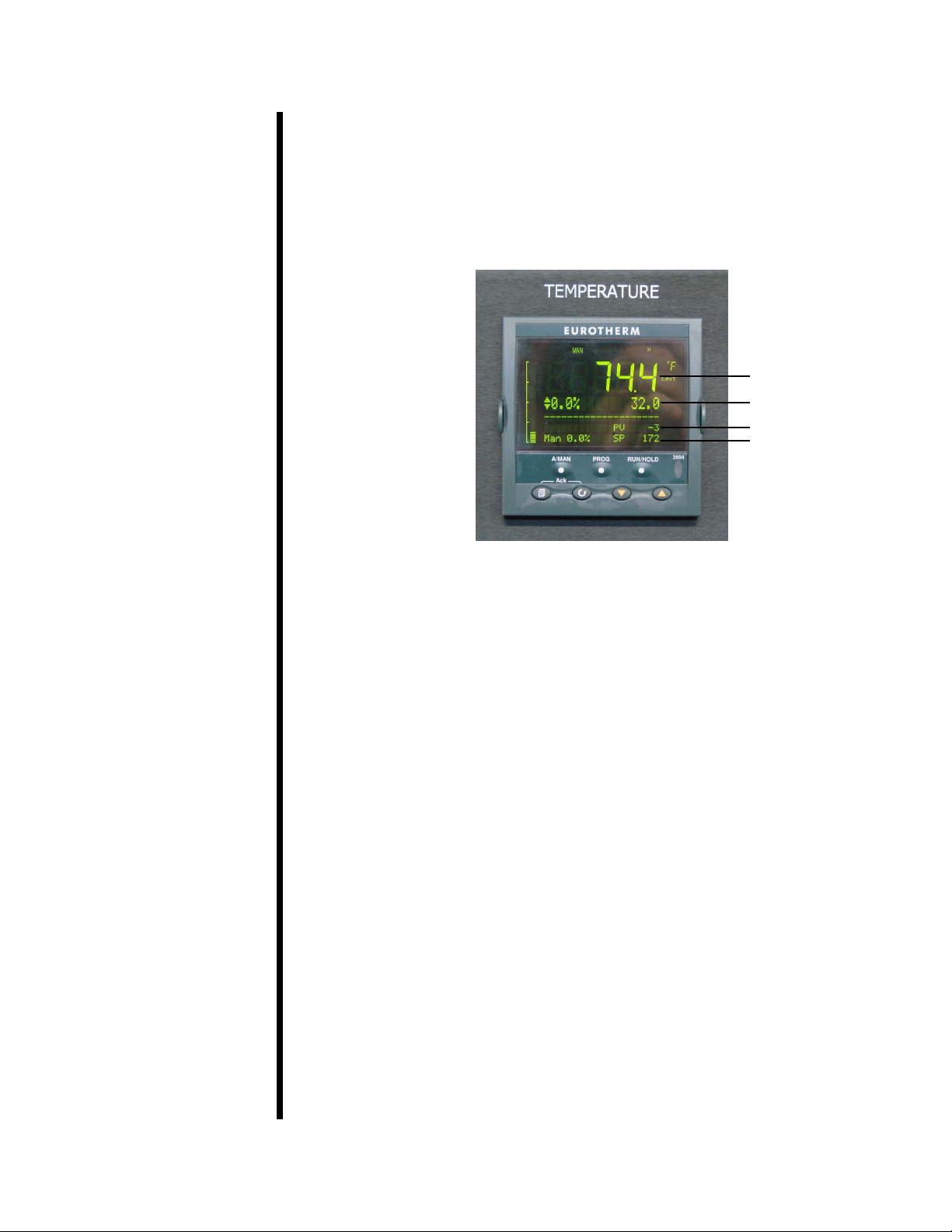
Temperature Controller:
The Eurotherm temperature controller shows the current temperature,
pressure, and setpoints. The temperature shown is the reading from either
the bath or slurry thermocouple, depending on the “Control Temp” value set in
“Testing Options”. See page 36 for more information.
Current Temp
Temp Setpoint
Current Pressure
Pressure Setpoint
Potentiometer Indicator:
The Potentiometer Indicator shows the DC voltage coming from the
potentiometer. This voltage is directly related to the consistency of the test
slurry (in Bc). The potentiometer has a range of 0 to 15 volts.
Status Indicator:
The lights on the Status Indicator correspond to the consistency of the
sample. The threshold values can be set in either the onboard controls or
in the software. There are three setpoints, specied in Bearden units of
consistency (Bc).
- Max Bc for Green Light: When the consistency is below this value, the
green light will be on.
- Max Bc for Green and Yellow: When the consistency is below this
value, the green and yellow lights will both be on.
- Max Bc for Red Light: When the consistency is below this value, the
yellow light only will be on. When the consistency is above this value,
the red light will be on and the test will stop.
Refer to page 38 for instructions on setting these values.
The Status Indicator also indicates an alarm condition. If an alarm is
triggered, all three lights on the status indicator will blink until the alarm is
acknowledged.
OFITE, 11302 Steeplecrest Dr., Houston, TX 77065 USA / Tel: 832-320-7300 / Fax: 713-880-9886 / www.ote.com 10

Chart Recorder:
The chart recorder keeps a running log of each test. This is an optional
feature and may not be included with your equipment.
Refer to the manufacturer documentation for more information.
Switches:
- MOTOR: Sets control of the motor When set to MANUAL, the motor
will turn at 150 RPM until stopped. When set to AUTOMATIC, the
motor will turn according to the parameters of the test that is currently
running. If no test is running, the motor will be stopped. When set to
OFF, the motor will not turn at all.
- DC VOLT: Controls power to the potentiometer. The potentiometer
should be turned off when there is no oil in the cell to prevent it from
overheating.
- CYLINDER: Controls the ow of oil into the cell. When FILL is
selected, oil ows into the cell for testing. When DRAIN is selected, oil
ows out of the cell and back into the reservoir.
- PUMP: Controls power to the pump. The pump adds pressure to the
cell as long as this switch is set to MANUAL. When AUTOMATIC is
selected, the pump is controlled by the electronic control board.
When OFF is selected, the pump will not run at all.
- HEAT: Controls power to the heaters. The heaters are controlled by
the electronic control board. Turning this switch on gives heat control
to the control board.
- COOL: Controls the cooling system. The cooling system is on and
cooling the cell as long as this switch is set to MANUAL. When
AUTOMATIC is selected, the cooling system is controlled by the
electronic control board. When OFF is selected, the cooling system
will not run at all.
- AIR TO CYLINDER: When this switch is on, air enters the cell and
forces the oil out into the reservoir.
- CHART RECORDER: Controls power to the chart recorder.
- MAIN: Controls power to the entire system. When this switch is off, all
other electronic systems in the Consistometer are also off.
OFITE, 11302 Steeplecrest Dr., Houston, TX 77065 USA / Tel: 832-320-7300 / Fax: 713-880-9886 / www.ote.com 11
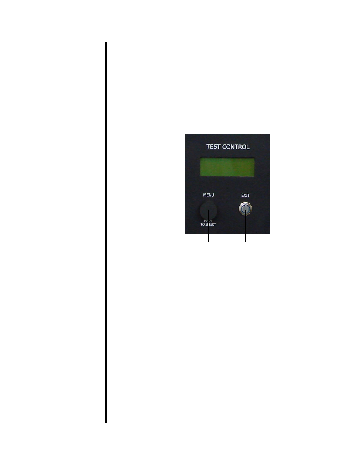
Test Control:
The on-board control panel consists of a display screen, a Scroll Wheel,
and an Exit button.
The Scroll Wheel turns clockwise and counterclockwise. Turning the wheel
scrolls through menu and parameter options. Pushing the Scroll Wheel in
signals acceptance.
The Exit button cancels any pending input and returns to the Main Menu.
Refer to page 31 for more information about the onboard control panel.
Scroll Wheel Exit Button
Thermocouple:
The Consistometer uses two thermocouples for reading temperature. One is
inside the unit cabinet and measures the temperature of the oil bath around
the slurry cup.
The other is outside the unit cabinet. This one must be inserted into the top
of the cell cap so that it reaches down into the slurry cup and measures the
temperature of the slurry.
When the thermocouple is not in use, store it in the port on the right-hand
side of the cabinet to protect it from damage.
OFITE, 11302 Steeplecrest Dr., Houston, TX 77065 USA / Tel: 832-320-7300 / Fax: 713-880-9886 / www.ote.com 12
Pressure Release Valve:
This valve releases the pressure in the test cell. To release the pressure,
slowly turn the valve counterclockwise. Always make sure the pump is turned
off and the cell temperature is below 200°F before releasing the pressure.
Always release the pressure very slowly to avoid pulling cement into
the plumbing.
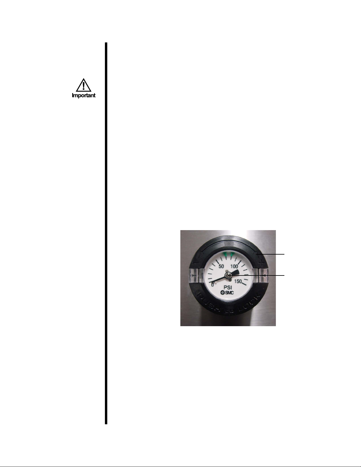
Air Pressure Regulator:
This regulator provides air pressure to the pump. When air pressure is
increased, each pump stroke adds more pressure to the test cell. If you
notice the pump repeatedly overshooting the pressure target, reduce the air
pressure and try again. If the pump seems to be pumping for too long, try
adding more air pressure.
To adjust the air pressure, pull the black locking ring out and turn the
regulator clockwise to increase pressure or counterclockwise to decrease it.
When you are nished, push the locking ring back in. The gauge set in the
regulator shows the current pressure.
Locking Ring
Gauge
OFITE, 11302 Steeplecrest Dr., Houston, TX 77065 USA / Tel: 832-320-7300 / Fax: 713-880-9886 / www.ote.com 13
Setup
Consistometer
1. Carefully remove the instrument from the wooden crate.
2. Once the unit is in place, lock the casters by depressing the lever on the
side. This will prevent the unit from moving.
3. Make sure all valves are closed and all switches are off. Connect an air
or nitrogen (100 – 120 PSI / 690 – 827 kPa) supply to the air supply on the
back of the instrument.
This unit uses ¼" NPT female connectors for all supply lines.
4. Connect the drain and coolant supply lines, also on the back of the unit.
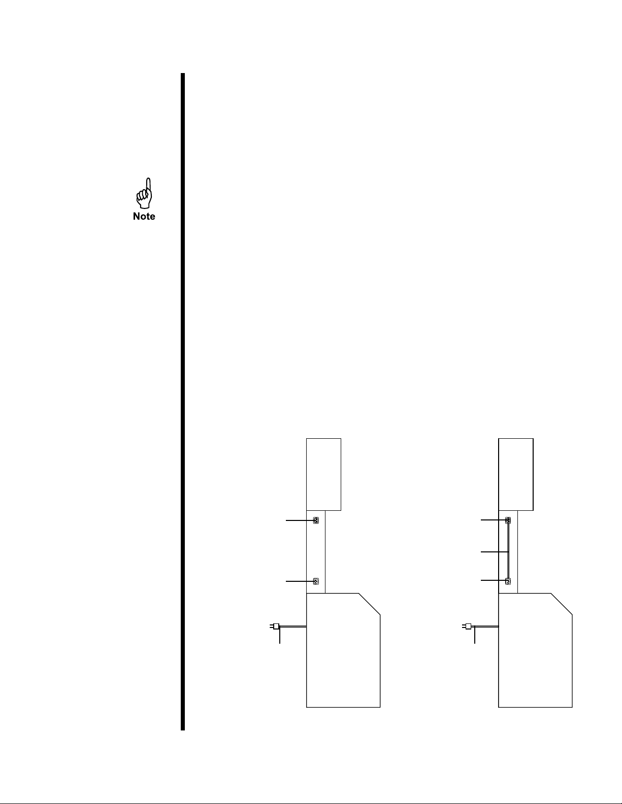
5. The consistometer has two power inlets. The large power cable on the
back of the cabinet provides power to the heaters. The lower inlet on the
left-hand side of the cabinet powers the rest of the electronics
To protect the electronics from a power outage, plug the inlet on the side
of the cabinet into an uninterruptible power supply (UPS). Then plug
the heater power cable into a 230 volt power source. In the event of a
power outage, the heaters will shut off, but the rest of the electronics will
continue to work and the test will keep running.
Above the electronics power inlet is a power outlet. To run the
Consistometer without the protection of a UPS, plug the electronics power
inlet into the power outlet above it. This will run the Consistometer using
power from the heater.
Power Outlet
(Not Used)
Power Inlet
(To UPS or 230VAC
Power Source)
Heater Power Cord
(To 230VAC Power
Source)
(To Power Inlet Below)
Power Outlet
Power Cord
(#130-76-10-4)
Power Inlet
(From Power
Outlet Above)
Heater Power Cord
(To 230VAC Power
Source)
With Uninterruptible
Power Supply
OFITE, 11302 Steeplecrest Dr., Houston, TX 77065 USA / Tel: 832-320-7300 / Fax: 713-880-9886 / www.ote.com 14
Without Uninterruptible
Power Supply

6. Turn the Main power switch on.
7. Set the date and time. See page 37.
8. To ll the oil reservoir, open the front cabinet door and remove the oil
reservoir cap. Pour approximately four liters (or until full) of oil into the
reservoir. Replace the cap. Make sure the seal is air tight. Use the sight
glass on the side of the reservoir to check the oil level.
Reservoir
Cap
Mineral Oil (#120-001) is recommended for tests up to 400°F. For
tests above 400°F, use only Phenylmethlsiloxane Silicone Fluid
(#120-004).
9. Turn the “Main Power” switch On.
10. Set the time and date on the on-board controller if they are not already
set. See page 37 for instructions.
11. Calibrate the potentiometer before connecting the Consistometer to a
computer. See page 38.
OFITE, 11302 Steeplecrest Dr., Houston, TX 77065 USA / Tel: 832-320-7300 / Fax: 713-880-9886 / www.ote.com 15
Operation
Filling the Slurry Cup
Three diaphragms are available for the slurry cup. For tests below
400°F, use OFITE part number 120-502. For tests above 400°F, use
OFITE part number 120-40-502. For tests below 200°F, use OFITE part
number 120-502-1.
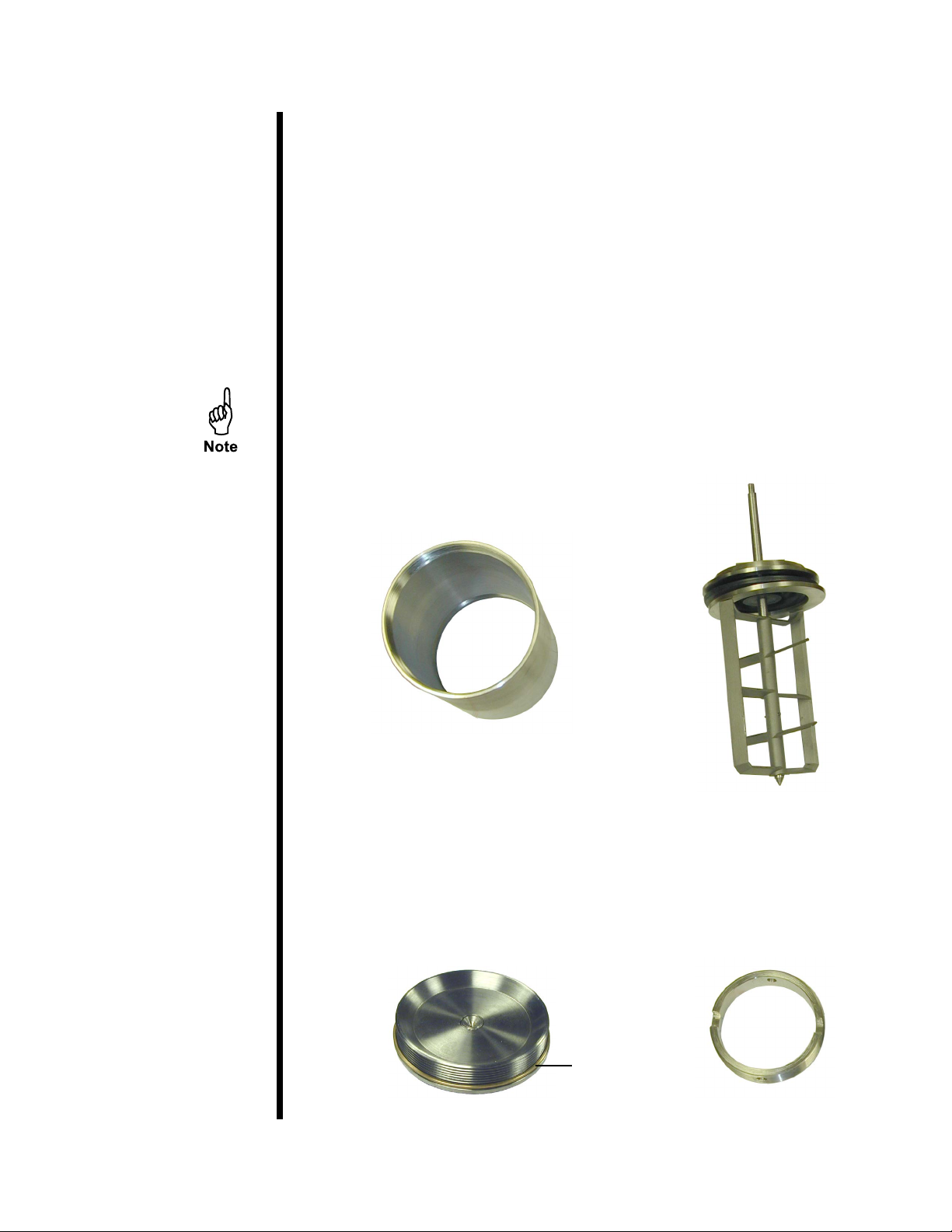
1. With the slurry cup disassembled, examine the threads on the inside of
the sleeve. The end with the larger set of threads is the top.
2. Coat the surface of the paddle and the inside of the slurry cup with a hightemperature grease to facilitate cement removal.
3. Insert the paddle assembly all the way into the top of the sleeve.
The slurry cup for the Model 2040 has a longer shaft (#120-520) and an
expansion chamber (#120-521) to accommodate cement expansion at
higher temperatures. See pages 59 and 60 for diagrams of the two
slurry cups.
Sleeve
Paddle
4. Slide the slurry cup lock ring on top of the paddle assembly with the two
notches facing upward. Tighten the locking ring completely using the
provided slurry cup tool.
Gasket
Base Locking Ring
OFITE, 11302 Steeplecrest Dr., Houston, TX 77065 USA / Tel: 832-320-7300 / Fax: 713-880-9886 / www.ote.com 16
5. Prepare the cement slurry as stated in API Specication 10.
6. Pour the cement into the slurry cup through the open bottom of the
sleeve.
7. Place the metal o-ring around the threads of the base. Apply hightemperature grease to the o-ring and base surface. Screw the base onto
the cup and tighten with the slurry cup tool.
The slurry cup should contain enough cement slurry that it leaks out of the
hole in the center of the base. If it does not, remove the base and rell the
slurry cup. Do not add cement through the hole in the base.
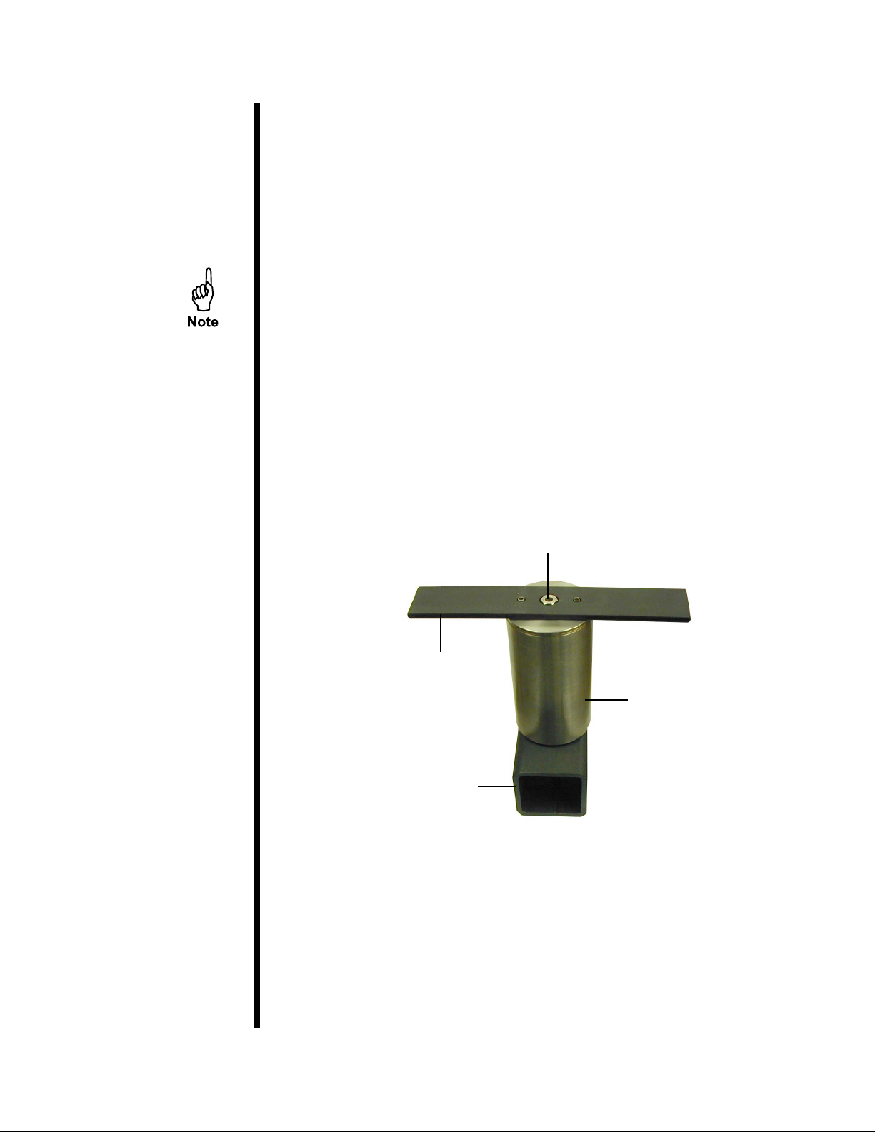
8. Screw the pivot bearing into the hole in the center of the base and tighten.
9. Wipe the entire slurry cup clean to ensure that no cement remains on the
outside.
Slurry Cup Tool
Slurry Cup Stand
Pivot Bearing
Slurry Cup
OFITE, 11302 Steeplecrest Dr., Houston, TX 77065 USA / Tel: 832-320-7300 / Fax: 713-880-9886 / www.ote.com 17
Operation
Starting a Test
1. Before turning on the Consistometer, make sure the MOTOR, PUMP,
HEAT, COOL, and AIR TO CYLINDER switches are all off and the
CYLINDER switch is set to DRAIN.
2. Turn the MAIN switch on.
3. Turn the MOTOR switch to MANUAL. This will start the motor.
4. Slowly lower the slurry cup into the test cell. When the slurry cup is
lowered all the way, the drive table will engage with the drive pins on the
bottom.
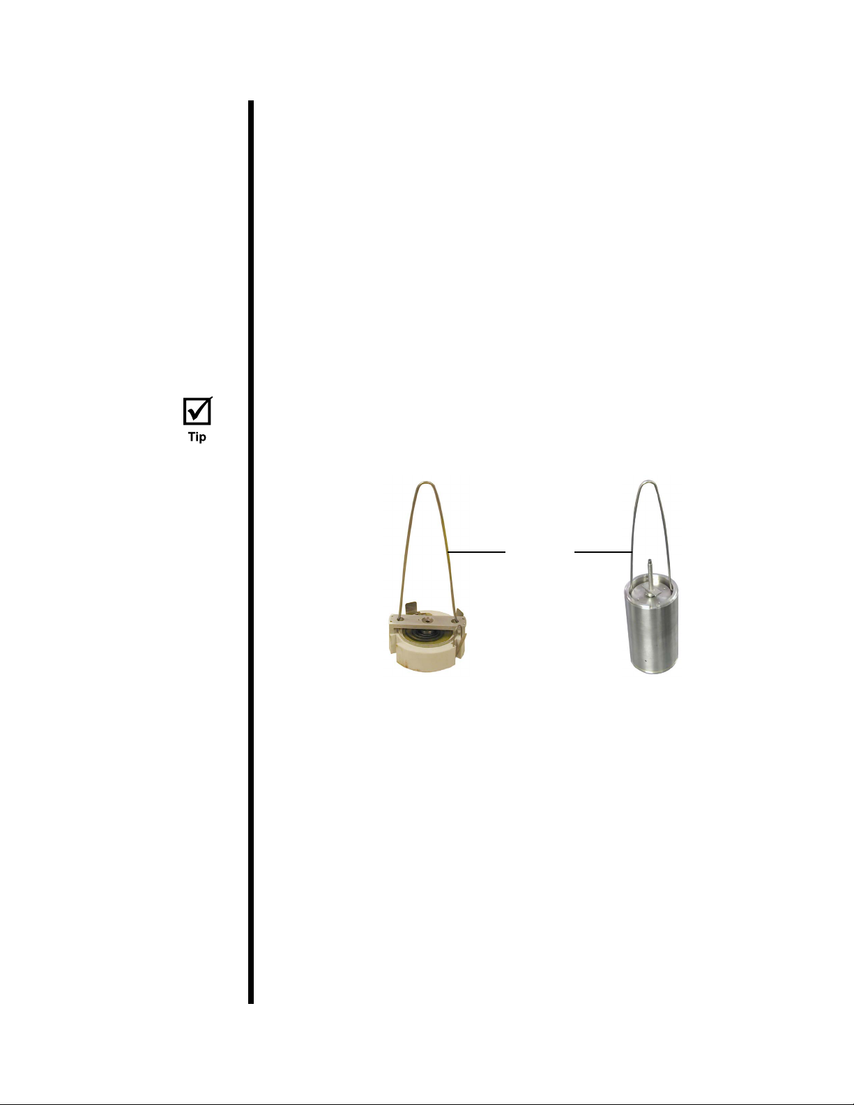
5. Lower the potentiometer into the test cell so that it sits on top of the slurry
cup. Make sure the three contacts on the potentiometer engage with the
contacts on the inside of the test cell.
The slurry cup and potentiometer both have two holes near the top for the
lift tongs (provided). Use the lift tongs to easily lower the slurry cup and
potentiometer into the test cell.
Lift Tongs
6. Turn the MOTOR switch to AUTOMATIC.
7. Carefully lower the cell cap into the test cell and tighten it.
8. Plug the thermocouple into the port near the test cell. Insert the
thermocouple into the hole in the top of the cell cap and tighten the thread
gland nger tight. Then loosen it ¼ of a turn.
9. Close the pressure release valve by turning it clockwise.
10. Turn the CYLINDER switch to FILL. This will begin lling the cell with
mineral oil. When the cell is full, oil will leak out of the thermocouple tting
on the cell cap. When this happens, tighten the tting to seal the cell.
OFITE, 11302 Steeplecrest Dr., Houston, TX 77065 USA / Tel: 832-320-7300 / Fax: 713-880-9886 / www.ote.com 18

11. Turn the PUMP switch to AUTOMATIC. Turn the DC VOLT and HEAT
switches on. And turn the COOL switch to AUTOMATIC.
12. Load the test:
a. If you will be using the software to run the test, click the Start Test
button on the Main Screen. This will open the “Load Test Infos” screen
and start the motor. Refer to page 21 for more information about
the software.
b. If you will be using the onboard controls to run the test, rst select a
test to run, then select option 1 “Run/Edit Test” from the Main menu
and press the Scroll Wheel in to start the test. This will start the motor.
Refer to page 31 for more information about the onboard controls.
13. Push the scroll wheel on the Control Panel to start the test.
OFITE, 11302 Steeplecrest Dr., Houston, TX 77065 USA / Tel: 832-320-7300 / Fax: 713-880-9886 / www.ote.com 19
Operation
Completing the Test
When the slurry consistency reaches the maximum consistency set in the
options (see page 36), the heater, motor, and pump will automatically turn
off and the cooling system will turn on. The red light on the Status Indicator
will turn on and an alarm will sound. To acknowledge the alarm, push the
Scroll Wheel.
1. Turn the HEAT, MOTOR, and DC VOLT switches off.
2. If the Chart Recorder is recording the test, open the door and push the
“REC” button to stop it.
3. Wait for the cell to cool. When the cell has cooled, turn off the
PUMP switch and slowly open the Pressure Release valve.
Never release pressure while the temperature is above 190°F.
If the pump switch is in the automatic position, the consistometer will
maintain pressure above 5,000 PSI as long as the temperature above
190°F.
Always release the pressure very slowly to avoid pulling cement into the
plumbing.
4. Turn the CYLINDER switch to DRAIN and turn the AIR TO CYLINDER
switch on. This will allow air into the test cell and force the oil back into
the reservoir.
5. When you hear air venting from the Consistometer, turn off the
AIR TO CYLINDER switch.
6. Remove the thermocouple from the cell cap.
7. Unscrew the cell cap and remove it from the test cell.
8. Remove the potentiometer and the slurry cup from the test cell.
9. Turn the COOL switch off.
10. Return the cell cap to the test cell to prevent dust and other material from
entering the cell. Turn the MAIN switch off.
OFITE, 11302 Steeplecrest Dr., Houston, TX 77065 USA / Tel: 832-320-7300 / Fax: 713-880-9886 / www.ote.com 20
Software
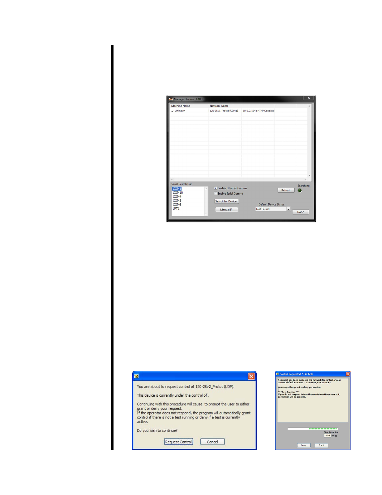
To open the software, double-click the “HTHP Consistometer” icon on the
desktop. The “Manage Devices” screen will automatically open. From this
screen you assume control of an HTHP Consistometer that is connected
to the network via Ethernet or directly connected to your computer via
RS-232 (serial). This screen can also be accessed by selecting “Manage
Devices” from the “Utilities” menu.
1. If the HTHP Consistometer is connected via Ethernet, make sure the
“Enable Ethernet Comms” option is selected. If it is connected via serial,
make sure “Enable Serial Comms” is selected.
2. If your instrument does not show up in the list at the top of the screen, click
the “Search for Devices” and “Refresh” buttons. If the device still doesn’t
show up, check the connection and try again. If the software is still unable
to locate the device, contact OFITE support.
3. Locate the device you want to manage. Right-click the device and click
“Select Default Device” to assume control.
4. If another user already has control of the device, you have the option
of requesting control. When you request control, the other user has 60
seconds to deny control, otherwise, control will automatically be transferred
to you.
5. Click “Done” to return to the main screen.
OFITE, 11302 Steeplecrest Dr., Houston, TX 77065 USA / Tel: 832-320-7300 / Fax: 713-880-9886 / www.ote.com 21
 Loading...