

OfiTE 1100, 130-81-C, 130-81-1-C Instruction Manual
Model 1100 Pressurized Viscometer
with ORCADA® Software Control System
#130-81-C - With Laptop PC and Padded Carrying Case, 115-Volt
#130-81-1-C - With Laptop PC and Padded Carrying Case, 230-Volt
Instruction Manual
Updated 4/25/2019
Ver. 10
OFI Testing Equipment, Inc.
11302 Steeplecrest Dr. · Houston, Texas · 77065 · U.S.A.
Tele: 832.320.7300 · Fax: 713.880.9886 · www.ote.com
©
Copyright OFITE 2015

Table of
Intro..................................................................................................2
Components ...................................................................................2
Contents
Features...........................................................................................4
Specications .................................................................................5
Setup................................................................................................7
Computer ....................................................................................7
Viscometer ..................................................................................8
System Test ................................................................................ 9
Preparing for a Test ................................................................... 11
Software Start ...............................................................................12
Calibration ..................................................................................... 16
Zeroing the Unit ........................................................................19
Fluid Manager ...........................................................................20
Operation.......................................................................................21
Manual Mode ............................................................................21
Auto Mode ................................................................................. 22
Software ........................................................................................23
Options ...................................................................................... 23
Save Rate Settings ...................................................................24
Test Builder ............................................................................... 25
Select Analysis Outputs ............................................................ 28
Saved Test Data ........................................................................ 29
Calibration History ..................................................................... 31
Import/Export ............................................................................32
Disassembly .................................................................................33
Maintenance .................................................................................. 35
Bob Shaft ..................................................................................35
Main Bearing Replacement .......................................................39
Rotor Nut ................................................................................... 42
Fuse Replacement .................................................................... 43
Appendix .......................................................................................44
Diagram ....................................................................................44
Transducer Linearization ........................................................... 46
Driver Install ..............................................................................49
Warranty and Return Policy ........................................................52
OFITE, 11302 Steeplecrest Dr., Houston, TX 77065 USA / Tel: 832-320-7300 / Fax: 713-880-9886 / www.ote.com 1

Intro
For enhanced data collection, OFITE is pleased to introduce the new Model
1100 Pressurized Viscometer. This fully-automated system accurately deter-
mines the ow characteristics of fracturing uids and drilling uids in terms of
shear stress, shear rate, time, and temperature at pressure up to 2500 PSI.
Using the exclusive ORCADA® software, a computer novice can operate the
Model 1100, and yet the system is versatile enough for advanced research
and demanding test parameters. The rugged Model 1100 is suitable for both
eld and laboratory use. A waterproof case with wheels makes the unit completely portable.
Components
#130-75-02 Cap O-ring, -036, Viton 75D
#130-75-04 Thermocouple O-ring, -002, Viton 75D
#130-75-20 " Spanner Wrench
#130-75-27 " T-handle Allen Key
#130-75-28 " Allen Key
#130-75-70 Waterproof Plastic Case with Casters
#130-78-04 Sample Thermocouple
#130-78-05 Main Seal
#130-78-13 B1 Bob; Hastelloy with Threads for Stainless Steel
#130-78-17 Bob Shaft Bearing
#130-78-18 Bearing, Main Body
#130-78-20 Rotor Cup O-ring, -218, Viton 70D
#130-78-34 Packing Washer
#130-78-36 O-ring, -117, Viton 75D
#130-79-15 Serial Cable; OB9; M/F
#130-81-001 O-ring, -029, Viton 75D
#130-81-002 Internal Pressure O-ring, -034, Viton 75D
#130-81-003 O-ring, -010, Viton 70D
#130-81-04 Spiral Retaining Ring
#130-81-07 Valve Stem
#130-81-071 Rotor, R1 (C276), HP
#130-81-082 Torsion spring, 4,000 Dyne/cm
#130-81-19 Bearing Retainer
#130-81-21 Seal Nut
#130-81-22 Lower Bearing
#130-81-27 Retaining Ring, VHM-28
#130-81-37 .050 Allen Key
#130-81-38 Seal Nut Wrench
#130-81-169 Shaft Assembly
#132-83 Calibration Fluid; 200 cP; 16 oz; Certied
#135-05 Spring Retaining Ring
#152-38 AC Power Cord; 3-Conductor International (Continental Euro-
pean)
#153-00 Bottle Brush
#153-55 Silicone Stopcock Grease; Dow Corning; 150g Tube
#153-67 60cc Disposable Syringe
#170-17 Valve Stem O-ring, -008, Viton 75D
2
OFITE, 11302 Steeplecrest Dr., Houston, TX 77065 USA / Tel: 832-320-7300 / Fax: 713-880-9886 / www.ote.com 2

Optional:
#132-80 100 cP Calibration Fluid; 16 oz.; Certied
#130-81-084 Torsion spring, 16,000 Dyne/cm
2
#132-82 500 cP Calibration Fluid; 16 oz.; Certied
#152-55 Bath/Circulator; Caron Model 2050W; Refrigerated and Heat-
ed; 115V
#152-55-1 Bath/Circulator; Caron Model 2050W; Refrigerated and Heat-
ed; 230V
#165-44-2 High-Temperature Thread Lubricant; 7 gram Pouch
OFITE, 11302 Steeplecrest Dr., Houston, TX 77065 USA / Tel: 832-320-7300 / Fax: 713-880-9886 / www.ote.com 3

Features
- High Pressure - Up to 2,500 PSI (17.2 MPa)
- High Temperature - Up to 500°F (260°C)
- Low Motor Shear Rates - As low as 0.01s-1
- Portable - The rugged carrying case is designed for eld or laboratory
use and is easy to transport.
- Small Footprint - Only 12" × 12" (30 × 30 cm). The all-in-one design
includes the heating mechanism.
- Couette Geometry - Uses traditional Bobs and Rotor for measurements
that are easy-to-translate (shear stress range 0 – 4000 dynes/cm
- Computer Controlled - Using the exclusive ORCADA
®
software system,
2
).
this viscometer is ideal for advanced research and demanding test
parameters.
- Data Acquisition - Store your data in a text format or in a Microsoft Excel
le for easy access and reporting capabilities.
- *SAFEHEAT
®
- Safe, Accurate, Fast, Environmentally friendly, High
Efciency Air Transfer system. Compared to traditional oil bath heating
systems, *SAFEHEAT® provides more precise control over the sample
temperature without the risks of hot oil, such as spilling, splashing or
ashing.
*U.S. Patent Number 8,739,609
OFITE, 11302 Steeplecrest Dr., Houston, TX 77065 USA / Tel: 832-320-7300 / Fax: 713-880-9886 / www.ote.com 4

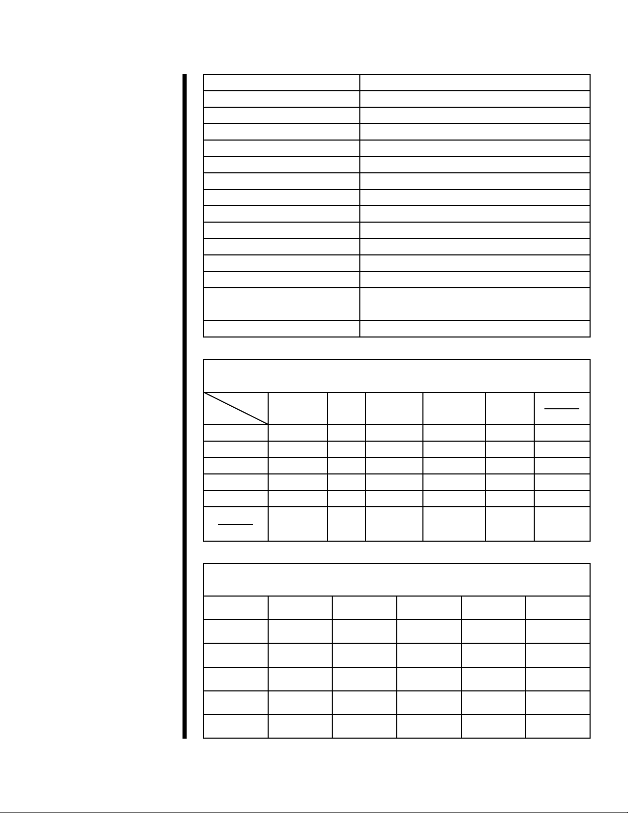
Specications
Range of Measurement for Model 1100
Rotor - Bob R1B1 R1B2 R1B3 R1B4 R1B5
Basic Data
Rotor Radius, RR (cm) 1.8415 1.8415 1.8415 1.8415 1.8415
Bob Radius, RB (cm) 1.7245 1.2276 0.8622 0.8622 1.5987
Bob Height, L (cm) 7.62 7.62 7.62 3.81 7.62
Shear Gap (cm) 0.117 0.6139 0.9793 0.9793 0.2428
R Ratio, RB/RR 0.9365 0.377 0.468 0.468 0.8503
Max Temperature (°C) 260 260 260 260 260
Min Temperature (°C) 0 0 0 0 0
Shear Stress Range (dyne/cm
Spring, 130-81-080 1 - 1000 2 - 2000 4 - 4000 8 - 8000 1 - 1160
Spring, 130-81-082 4 - 4000 8 - 8000 16 - 16000 32 - 3200 4 - 4650
Spring, 130-81-084 16 -16000 32 - 32000 64 - 64000 128-128000 19-18600
Shear Rate Range*
2
)
Shear Rate Constant
-1
(s
/ RPM)
Shear Rate Range (s
1.7023 0.3770 0.2682 0.2682 0.8503
-1
)
0.01 RPM 0.01702 0.00377 0.00238 0.00238 0.008503
0.1 RPM 0.1702 0.0377 0.02382 0.02382 0.08503
1.0 RPM 1.702 0.377 0.2382 0.2382 0.8503
10 RPM 17.02 3.77 2.382 2.382 8.503
100 RPM 170.2 37.7 23.82 23.82 85.03
1000 RPM 1702 377 238.2 238.2 850.3
Viscosity Range (cP)
Minimum Viscosity
with 130-81-080**
Maximum Viscosity
with 130-81-080***
Minimum Viscosity
with 130-81-082**
Maximum Viscosity
with 130-81-082***
Minimum Viscosity
with 130-81-084**
Maximum Viscosity
with 130-81-084***
0.1 0.5 1.7 3.4 0.1
5,875,000 53,125,000 168,750,000 337,500,000 13,750,000
0.2 2.1 6.8 13.6 0.5
23,500,000 212,500,000 675,000,000 1,350,000,000 55,000,000
1.0 8.5 27.2 54.4 1.9
94,000,000 850,000,000 2,700,000,000 5,400,000,000 220,000,000
* Lower shear rates available on special order.
** At 1,000 RPM
*** At .01 RPM
When using the 130-81-079 spring use a maximum speed of 300 RPM.
OFITE, 11302 Steeplecrest Dr., Houston, TX 77065 USA / Tel: 832-320-7300 / Fax: 713-880-9886 / www.ote.com 5
Instrument Geometry True Couette Coaxial Cylinder
Motor Technology Stepper
Motor Speeds (RPM) Variable Speed Range .01 - 1,000
Speed Accuracy (RPM) .001
Shear Rate Range (sec
-1
) .01 - 1,022
Readout Computer Control and Data Acquisition
Heat System 300 Watt, Max Temp 500°F (260°C)
Temperature Measurement Type “J” Thermocouple
Automatic Tests API Cementing, Mud and Fracture Rheology
Power Requirements 115 or 230 Volts AC, 50/60 Hz
Weight 85 lbs (37.6 kg)
Dimensions 14" × 13" × 30" (36 × 33 × 76 cm)
Shipping Weight 150 lbs (68 kg)
Communication
Requirements
RS-232 Serial Port or LAN or Bluetooth.
Operating System Windows 2000, XP or higher.
Viscosity Conversions
To convert from units on left side to units on top, multiply by factor @ intercept.
To
From
Centipoise
(cP)
Poise
(P)
g/(cm × s) (mN × s)m
2
mPa × s
Centipoise 1 0.01 0.01 1 1 0.002088
Poise 100 1 1 100 100 0.2088
g/(cm × s) 100 1 1 100 100 0.2088
(mN × s)m
2
1 0.01 0.01 1 1 0.002088
mPa × s 1 0.01 0.01 1 1 0.002088
lb × s
100 ft
2
478.93 4.789 4.789 478.93 478.93 1
Shear Stress Conversions
To convert from units on left side to units on top, multiply by factor @ intercept.
(lb × s)
100 ft
2
Dyne/cm
2
Dyne/cm
2
Pa lb/100ft
1 0.1 0.2084 0.002084 0.1957
2
lb/ft
2
DR
Pa 10 1 2.084 0.02084 1.957
lb/100ft
2
lb/ft
2
4.788 0.4788 1 0.01 0.939
478.8 47.88 100 1 93.9
DR 5.107 0.5107 1.065 0.01065 1
OFITE, 11302 Steeplecrest Dr., Houston, TX 77065 USA / Tel: 832-320-7300 / Fax: 713-880-9886 / www.ote.com 6

Setup
Computer
1. First, check that the computer’s AC power setting matches the available
power in your region. This switch is typically found on the upper back
panel of the computer and will be either 115V or 230V.
2. Connect the monitor, mouse, and keyboard to the computer and connect
the monitor and computer to an AC power outlet. The computer and
monitor were shipped with the appropriate power cords.
If your Model 1100 was supplied with a laptop computer instead of a
desktop model, simply open the laptop and turn the power on. The
AC power cord can be used to prevent the battery from draining
completely during operation. Remember to periodically charge the
battery by leaving the AC power cord plugged in overnight.
3. Turn the monitor and computer on. After the computer has booted up
completely, check for the ORCADA® icon on the desktop.
OFITE, 11302 Steeplecrest Dr., Houston, TX 77065 USA / Tel: 832-320-7300 / Fax: 713-880-9886 / www.ote.com 7
Setup
Viscometer
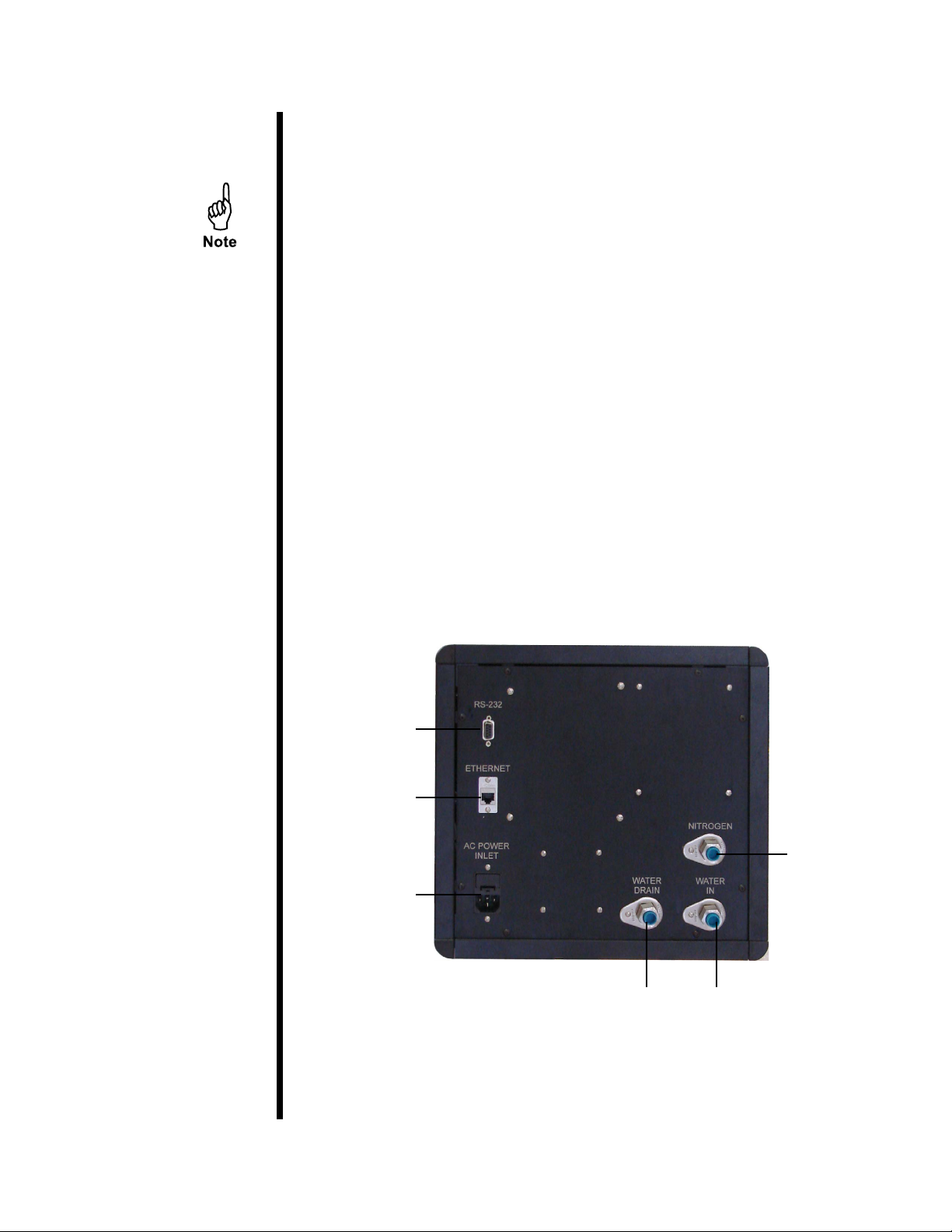
1. On the back panel, locate the three ¼" (6.35mm) NPT ttings. Connect
a water source (15 - 30 PSI / 104 - 208 kPa), Nitrogen source, and drain
hose to the appropriate ttings.
The Nitrogen is used to pressurize the sample and prevent boiling at
temperatures above 212°F (100°C). The water is used to raise and lower
the heater.
2. Screw the heater cable from the heat bath into the bottom of the cabinet.
3. Plug the thermocouple from the heat bath into the bottom of the cabinet.
4. Connect the viscometer to the computer using either a 9-pin RS232
cable, a Local Area Network connection with an Ethernet cable, or
Bluetooth.
5. Make sure the “Power” switch is in the off position. Plug the power cord
into an AC power source.
Serial Port
Ethernet Port
Nitrogen
Power
Drain Water In
OFITE, 11302 Steeplecrest Dr., Houston, TX 77065 USA / Tel: 832-320-7300 / Fax: 713-880-9886 / www.ote.com 8
Setup
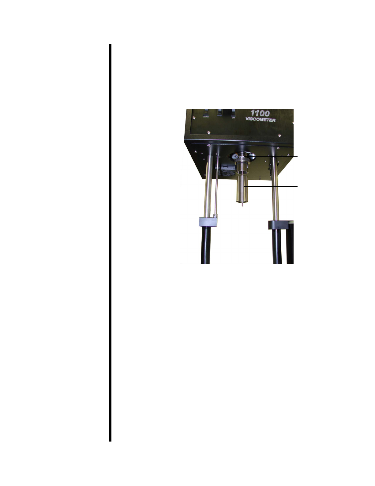
1. Turn the unit on. The power switch is located on the front panel.
System Test
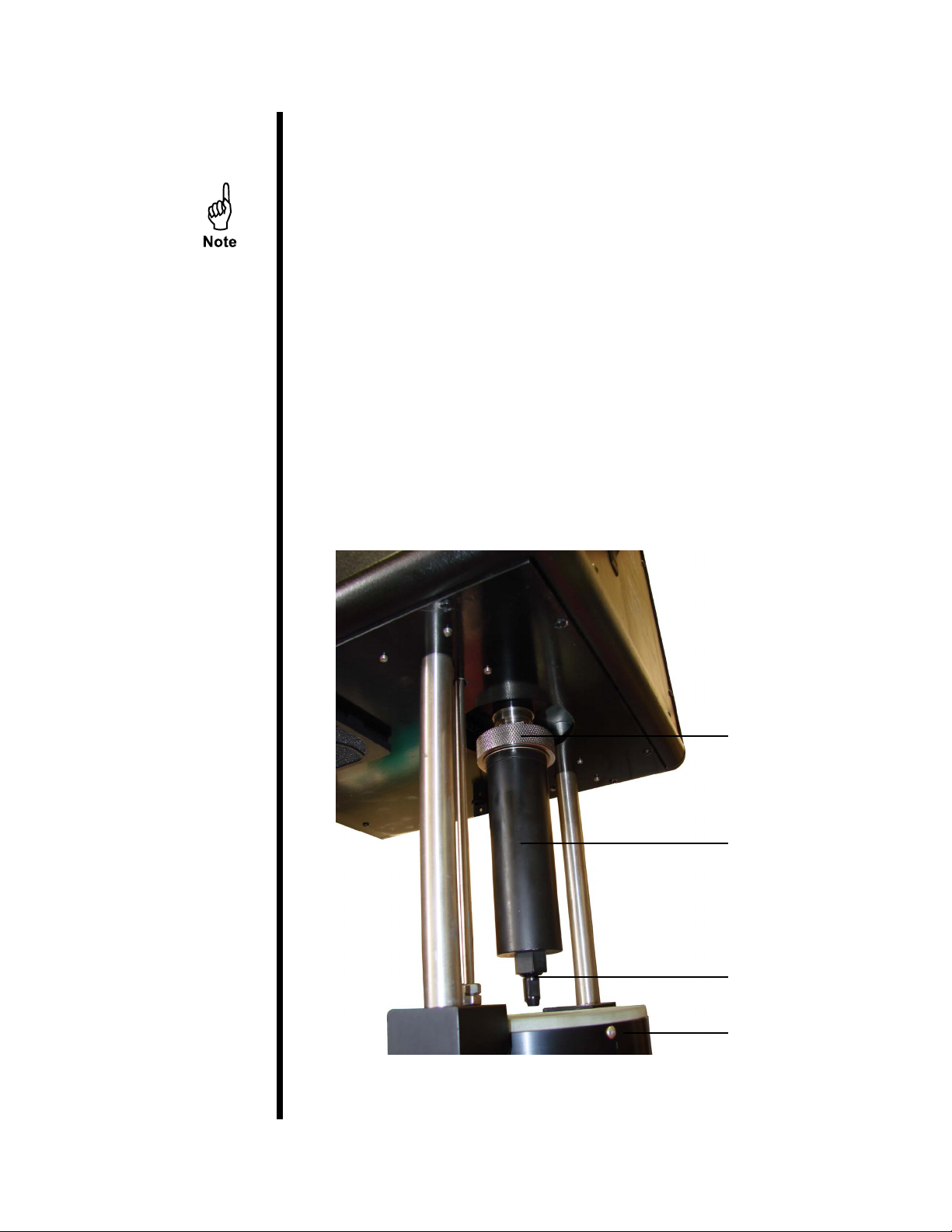
2. If the heater is raised, lower it using the “Heater Lift/Lower” switch.
The sample cup is already attached to the viscometer in order to protect
the bob shaft during shipping. Always handle the bob shaft carefully;
bending it will result in poor viscosity readings.
3. To remove the sample cup, unscrew the sample cup nut and pull the
sample cup straight down.
4. Carefully apply a thin coating of high-temperature thread lubricant (#16544-2) to the bob shaft threads.
5. To install the bob, slide it onto the bob shaft with the tapered end down
and screw it securely into place. An R1B1 bob/rotor combination is
standard for the Model 1100 Viscometer, however other combinations are
available. See page 5 for more information.
Sample Cup Nut
Sample Cup
Valve Stem
Heat Bath
OFITE, 11302 Steeplecrest Dr., Houston, TX 77065 USA / Tel: 832-320-7300 / Fax: 713-880-9886 / www.ote.com 9
6. Turn on the computer and open the ORCADA® software (see page
12 for instructions).
7. From the menu bar at the top of the screen, select “Utilities” and then
“Calibrate Shear Stress”. Check the “Temperature” eld to verify that
it shows room temperature. Then, conrm that the value in the “Shear
Stress Raw” uctuates when you gently turn the bob with your hand.
Expansion
Fitting
Bob
If either of these values does not display as expected, make sure the
Model 1100 is turned on and that all cables are securely connected. If the
problem is still not corrected, return to the “Main Screen” in the ORCADA®
software and choose “Edits” and then “Options”. In the “COM Port” dropdown menu, choose a different port and try again. See page 23 for
information about the “Options” screen.
8. It is recommended that a Calibration procedure be run due
to the possibility of mishandling during shipment. Refer to the
“Calibration” section on page 16 for detailed instructions on calibrating
the unit.
OFITE, 11302 Steeplecrest Dr., Houston, TX 77065 USA / Tel: 832-320-7300 / Fax: 713-880-9886 / www.ote.com 10
Setup
1. Install the bob as described in steps 1 - 6 on page 9.
Preparing for a Test
2. Fill the sample cup with the proper amount of uid based on the bob you
are using. Refer to the chart below.
Body Type B1 B2 B3 B4 B5 XB1 XB2 XB5
Sample Amount (mL) 42 78 96 104 52 32 73 44
3. Hold the sample cup by hand and position the bob in the center. Push the
sample cup up past the o-ring. Hold the sample cup in place and screw
the sample cup nut into place.
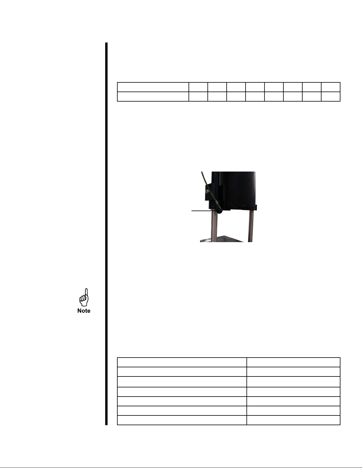
4. Position the heat bath under the sample cup and raise it. The bath can be
raised either manually and secured with the supplied pin or automatically
with the “Heater Lift / Lower” switch. Press the button to release.
Lock Pin
5. To pressurize the sample, gradually rotate the regulator knob clockwise.
To reduce pressure, gradually rotate the regulator knob counterclockwise
at a rate no greater than 60 PSI per minute.
Pressure is only necessary for tests temperatures above 200°F (95°C).
The heaters will be deactivated if the sample is not pressurized enough
to prevent boiling. The ORCADA® software will indicate this with a yellow
alarm light. The alarm light will turn green when the appropriate pressure
is applied to the sample. Refer to the chart below for the minimum
pressure requirements.
6. Once the pressure is set and the heater is in place, the Model 1100 is
ready to run a test.
Temperature Pressure
Ambient - 200°F (Ambient - 93.3°C) 0 PSI (0 kPa)
201° - 295°F (93.9° - 146.1°C) 100 PSI (690 kPa)
296° - 355°F (146.7° - 179.6°C) 200 PSI (1,380 kPa)
356° - 395°F (180.1° - 201.8°C) 300 PSI (2,070 kPa)
396° - 445°F (202.4° - 229.6°C) 500 PSI (3,450 kPa)
446° - 500°F (230.2° - 260.2°C) 800 PSI (5,520 kPa)
OFITE, 11302 Steeplecrest Dr., Houston, TX 77065 USA / Tel: 832-320-7300 / Fax: 713-880-9886 / www.ote.com 11
Software Start
1. Double-click the “ORCADA®” icon on the desktop.
2. The rst time you run the software, you will be asked to select a hardware
conguration. Select “Model 1100 v2” and click “OK”. You will now see the
Main Screen.
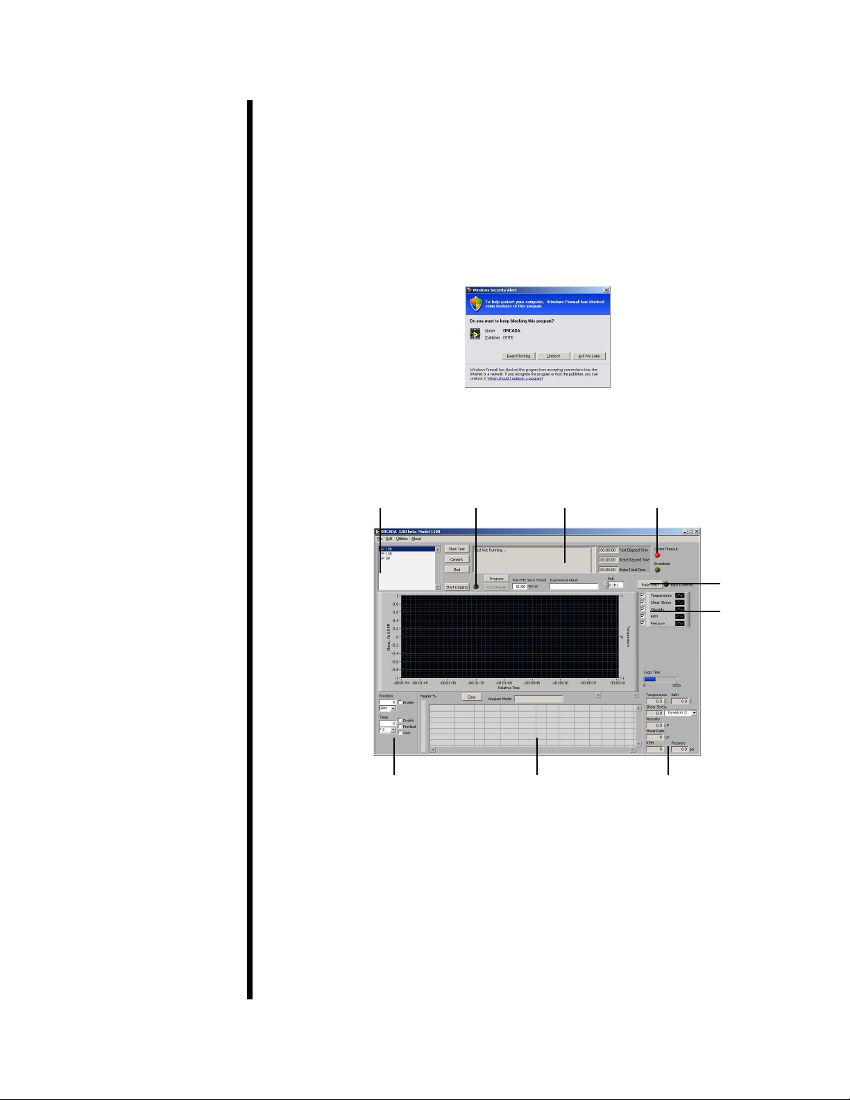
3. The Windows XP rewall may try to block the ORCADA® software from
communicating with the viscometer. If the rewall shows the following
alert, select “Unblock”.
Windows XP Firewall Alert
Main Screen
Communication
Available Tests Log Indicator Status
Indicator
Bath Control
Key
Manual Mode
Controls
Analysis Data Process Variables
“Start Test” - This button starts a test in Auto Mode. Once a test is started,
this button becomes the “Abort Test” button. Click here to stop the test.
“Cement” - This button performs a standard cement test based on
API specications.
“Mud” - This button performs a standard mud test based on
API Specications.
OFITE, 11302 Steeplecrest Dr., Houston, TX 77065 USA / Tel: 832-320-7300 / Fax: 713-880-9886 / www.ote.com 12
Note: When running the “Mud” and “Cement” tests, the values for
“Dead Time” and “DAQ Time” on the Options screen should be ignored.
Temperature and pressure control, which are disabled during custom AutoMode tests, are available during a “Mud” or “Cement” test.
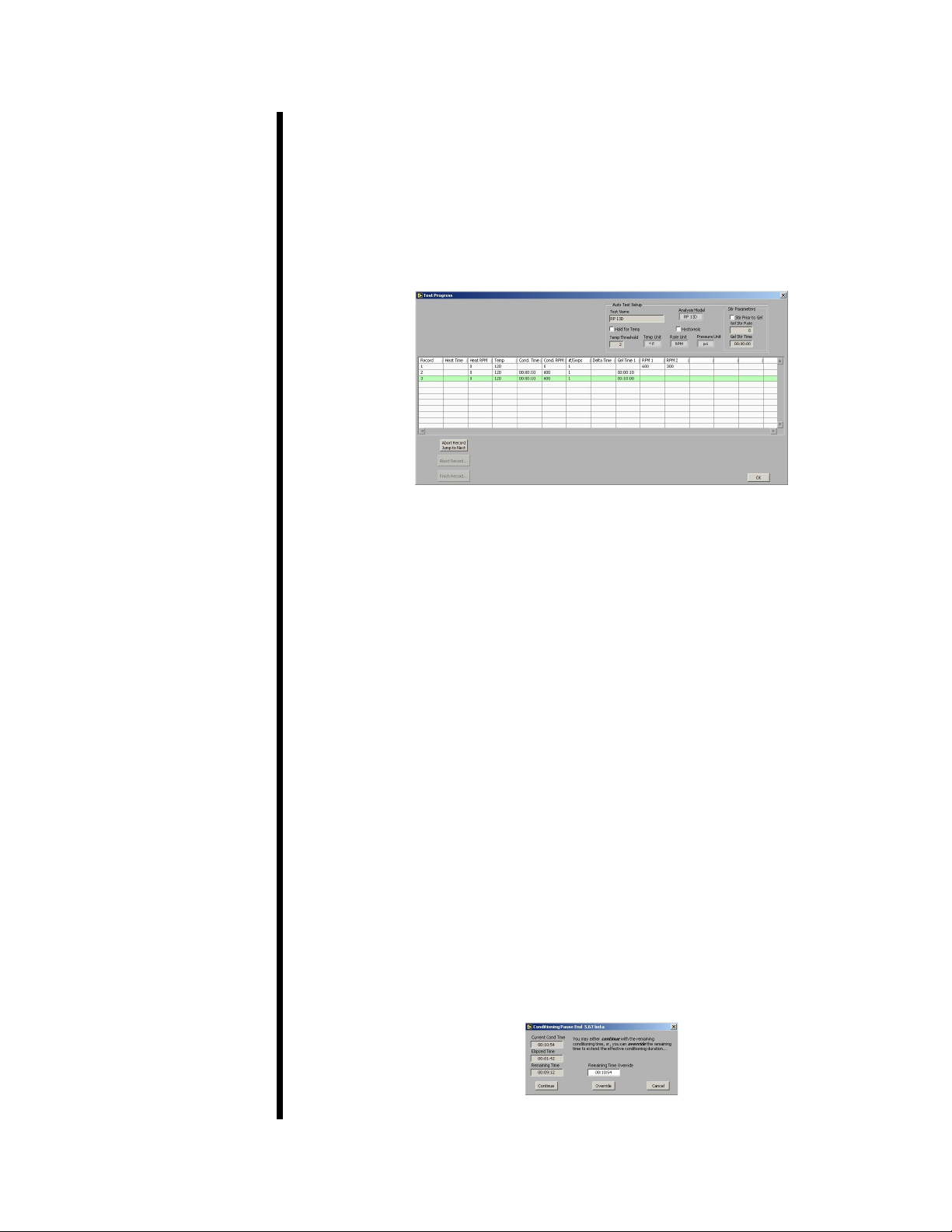
“Progress” - This button opens the Test Progress window, which shows all of
the steps of the current test and highlights the one currently in process.
“Status” - This box at the top of the screen shows the current status of the
test.
“Comm Timeout” - This light will be off when the PC is successfully
communicating with the viscometer. If communication is interrupted for any
reason, the light will shine red to indicate a problem.
“Start Logging” - This button is available in manual mode only. Click here to
begin recording test data. The light next to this button will shine green while
logging is in progress.
“Cond Pause” - This button will pause a test during the conditioning phase
and put the software into Manual Mode. While the test is paused, the motor
and heat controls can be controlled in the same manner as in a standard
Manual Mode test.
To resume the test, click the “Cond Pause” button again. You will be asked if
you want to “Continue” the test with the remaining conditioning time or if you
want to “Override” the remaining time and extend the effective conditioning
time. If you choose to “Continue”, the time remaining in the conditioning cycle
will appear as though the test was never paused. If you choose to “Override”,
the time remaining in the conditioning cycle will resume at the point where the
test was paused.
OFITE, 11302 Steeplecrest Dr., Houston, TX 77065 USA / Tel: 832-320-7300 / Fax: 713-880-9886 / www.ote.com 13

For example, assume a test has a conditioning time of 10 minutes and the
test is paused at the 5 minute mark for 1 minute. If the test is unpaused
using the “Continue” option, the time remaining in the conditioning cycle will
be 4 minutes. However, if the test is unpaused using the “Override” option,
the time remaining in the conditioning cycle will be ve minutes, making the
effective total conditioning time 11 minutes.
“Raw File Save Period” - This eld determines how often data is recorded
during a test.
“Experiment Name” - This eld will be used to identify the experiment later.
This eld is required before starting a test in Auto Mode or starting logging in
Manual Mode.
“Bob” - Select the type of bob currently being used in the unit. An incorrect
value in this eld will adversely affect your test results.
“Key” - The checkboxes next to the graph key enable and disable graphing
of the indicated values. For example, to exclude RPM from the graph,
uncheck the “RPM” box. You can also customize the appearance of the lines
on the graph by clicking on the line example on the right side of the key.
“Manual Mode Controls” - The manual mode controls, in the bottom lefthand corner of the screen, adjust the rotor speed and the temperature while
the unit is operating in manual mode.
“Rotation” - This eld determines the rotational speed. The drop-down
box beneath the eld set the units to either RPM or 1/s.
“Enable” - Place a check in this box to engage the motor. Uncheck the
box to stop the motor.
“Temp” - This eld determines the test temperature. The drop-down list
beneath the eld sets the units to either °F or °C.
“Enable” - Place a check in this box to enable temperature control. If
the value in the “Temp” eld is higher than the sample temperature, the
heaters will engage to heat the sample.
“PreHeat” - The software will not heat a sample above 200°F (93°C)
unless the sample is pressurized. The preheat button allows the software
to heat the bath to higher temperatures without giving a low pressure
warning. Enter a value in the “Temp” eld and check the “PreHeat” box to
preheat the bath prior to heating the sample.
OFITE, 11302 Steeplecrest Dr., Houston, TX 77065 USA / Tel: 832-320-7300 / Fax: 713-880-9886 / www.ote.com 14

“Cool” - Place a check in this box to activate the cooling solenoid and
begin cooling the sample. The value in the “Temp” eld must be lower
than the sample for the software to initiate cooling.
“Clear” - This button removes all data from the graph.
“Analysis Model” - This eld, below the graph, displays the current Analysis
Model being used in the test. This variable is set in the Test Builder (refer to
page 25 for more information).
“Analysis Data” - This chart shows the calculated values based on the
Analysis Model being used for the test. This data will not display until after the
analysis sweep is completed.
“Temperature”, “Shear Stress”, “Viscosity”, “Shear Rate”, “RPM” -
These elds display the current value for these variables. They are display
only. The drop-down box next to the “Shear Stress” eld changes the units of
the Shear Stress variable. The units can be set to: Dyne/cm2, lb/100ft2, Pa.,
Dial Reading, lb/ft
2
OFITE, 11302 Steeplecrest Dr., Houston, TX 77065 USA / Tel: 832-320-7300 / Fax: 713-880-9886 / www.ote.com 15
 Loading...