

OfiTE 130, 120-90, 120-90-DAS Instruction Manual

Model 130 Benchtop Consistometer
#120-90-DAS - With Computer for Data Acquisition and Control
Instruction Manual
11302 Steeplecrest Dr. · Houston, Texas · 77065 · U.S.A.
Tele: 832.320.7300 · Fax: 713.880.9886 · www.ote.com
#120-90 - Standard
Updated 4/24/2018
Ver. 6.0
OFI Testing Equipment, Inc.
©
Copyright OFITE 2015

Table of
Intro..................................................................................................2
Description ...................................................................................... 2
Contents
Features...........................................................................................2
Requirements .................................................................................2
Specications .................................................................................3
Components ...................................................................................3
Setup................................................................................................5
Consistometer ............................................................................. 5
Chart Recorder ...........................................................................6
Eurotherm .................................................................................10
Potentiometer Indicator ............................................................. 12
Software ........................................................................................13
Setup ......................................................................................... 13
Calibration ................................................................................. 16
Operation ..................................................................................17
Test Builder ............................................................................... 18
Test Data ................................................................................... 19
Operation.......................................................................................20
Filling the Slurry Cup ................................................................. 20
Loading the Test Cell ................................................................ 22
Completing the Test .................................................................. 25
Maintenance .................................................................................. 26
Potentiometer ........................................................................... 27
Appendix .......................................................................................29
Potentiometer Calibration .........................................................29
Potentiometer Adjustment .........................................................31
Diagrams ................................................................................... 32
Warranty and Return Policy ........................................................34
OFITE, 11302 Steeplecrest Dr., Houston, TX 77065 USA / Tel: 832-320-7300 / Fax: 713-880-9886 / www.ote.com 1

Intro
During cementing operations, the time required for a cement slurry to set is
of primary concern. Under an ideal situation, minimal time would be required
to successfully pump the slurry, which immediately upon placement, begins
to develop compressive strength. However, if insufcient time is allowed to
fully pump the cement, it will be necessary to drill the cement remaining in the
casing string. Remedial operations such as this are very costly. Conversely,
cements that are successfully placed, but require considerable time to
cure, consume valuable rig time, which is also quite costly. Laboratory tests
should be conducted under simulated reservoir conditions to examine the
actual thickening time of the slurry. The OFITE Benchtop Consistometer
was specically engineered to determine the thickening time of well cements
under simulated downhole pressures and temperatures.
Description
Features
A cement is mixed and poured into the slurry cup assembly. The slurry cup
is placed into the test vessel and pressure is increased via an air-driven
hydraulic pump. A PID temperature controller governs an internal heater,
which maintains the necessary temperature prole, while a magnetic drive
mechanism rotates the slurry cup assembly at 150 RPM. A potentiometer
controls an output voltage, which is directly proportional to the amount of
torque the cement exerts upon an API-approved paddle. A chart recorder
registers cement consistency and temperature as a function of time.
Temperature and consistency are digitally displayed via LED indicators.
- Maximum Pressure: 16,000 PSI (110.3 MPa)
- Maximum Temperature: 400°F (204.4°C)
- Pressure generated via an air-driven hydraulic pump
- Drive table is rotated with a magnetic drive
- External cooling jacket aids cooling of test cell
- Electronic timer with alarm, elapsed 0.1 minute resolution
- Deadweight calibration unit included
- Temperature and consistency alarms provide automatic shutdown
- Safety head with rupture disk are provided
- Unit is fully capable of testing cements in strict accordance to the
guidelines as stated in API Specication 10
Requirements
OFITE, 11302 Steeplecrest Dr., Houston, TX 77065 USA / Tel: 832-320-7300 / Fax: 713-880-9886 / www.ote.com 2
- Air/Nitrogen Supply (100 - 150 PSI / 690 - 1,035 kPa)
- Water Supply for Cooling (40 PSI / 276 kPa)
- Water Drain
- 220 Volt, 50/60 Hz, 25 Amp electrical power supply

Specications
Size 25 × 16 × 20 inches (63.5 × 40.6 × 50.8 cm)
Weight 215 lb (94.6 kg)
Crated Size 30 × 20 × 24 inches (76.2 × 50.8 × 61 cm)
Crated Weight 255 lb (115.8 kg)
Temperature Controller Digital PID, 1° Resolution
Internal Heater 2,500 Watt (5,000 Watt Available)
Components
Slurry Cup
Maximum Temperature 400°F (204.4°C)
Maximum Pressure 16,000 PSI (110.3 MPa)
#120-00-026-1 Timer
#120-00-028 Consistency Indicator, Eurotherm 2408i
#120-001 Mineral Oil, 1 Gallon, Qty: 3
#120-104 Rupture Disk, 17,500 PSI
#120-208-1 Slurry Cup Thermocouple
#120-519 Slurry Cup Assembly, No Expansion Cap
#120-502 Molded Diaphragm
#120-503 Paddle Pin
#120-506 Paddle
#120-90-5 Chart Recorder, Eurotherm 6100A
#120-90-033 Air Filter
#120-90-035 Filter
#120-90-63 Temperature Controller, Eurotherm 3504
#130-79-15 Serial Cable
#130-76-16 USB Cable
#152-38 Power Cable
#120-628 Potentiometer Assembly:
#120-602 Calibration Spring
#120-603 Potentiometer Body
#120-604 Potentiometer Resistor
#120-605 Contact Spring
#120-606 Potentiometer Contact Arm
#120-607 Contact Strip
#120-608 Grounding Cable Retaining Screw
#120-609 Grounding Contact Spring
#120-75-10 Slotted Weight Set
#120-75-9 Weight Hanger
150 RPM Rotational Speed; 316 Stainless Steel;
Expansion Chamber
OFITE, 11302 Steeplecrest Dr., Houston, TX 77065 USA / Tel: 832-320-7300 / Fax: 713-880-9886 / www.ote.com 3

#120-90-00 Cell Assembly:
120-90-049 Cell Cap Backup Ring
120-146 Mag Drive O-ring
120-147 Mag Drive
120-148 Retaining Ring
120-149 Test Cell O-ring
120-206 2,500 Watt Heater
120-257 Drain Plug O-ring
503-258V90 O-Ring, Qty: 2
#120-91 Spare Parts for #120-90:
#120-001 Mineral Oil, 1 Gallon, Qty: 2
#120-104 Rupture Disk, 17,500 PSI, Qty: 3
#120-105 High-Pressure Check Valve
#120-146 Mag Drive O-ring, Qty: 12
#120-148 Cell Cap Backup Ring, Qty: 2
#120-149 Test Cell O-ring, Qty: 12
#120-204 Heater Gasket, Qty: 2
#120-208-1 Slurry Cup Thermocouple, Qty: 2
#120-257 Drain Plug O-ring, Qty: 12
#120-501 Slurry Cup Sleeve, Qty: 2
#120-502 Molded Diaphragm, Qty: 25
#120-503 Paddle Pin, Qty: 24
#120-504 Pivot Bearing, Qty: 10
#120-505 Pivot Bearing Gasket, Qty: 5
#120-506 Paddle, Qty: 6
#120-507 7¾" Paddle Shaft, Qty: 10
#120-508 Diaphragm Retaining Ring, Qty: 6
#120-509 Drive Disc
#120-510 Drive Bar
#120-511 Slurry Cup Shear Pin, Qty: 24
#120-512 Slurry Cup Drive Pin, Qty: 12
#120-513 Slurry Cup Gasket, Qty: 12
#120-519 Slurry Cup Assembly, No Expansion Cap
#120-602 Calibration Spring, Qty: 6
#120-604 Potentiometer Resistor, Qty: 6
#120-606 Potentiometer Contact Arm, Qty: 6
#120-607 Contact Strip, Qty: 6
#120-628 Potentiometer Assembly
OFITE, 11302 Steeplecrest Dr., Houston, TX 77065 USA / Tel: 832-320-7300 / Fax: 713-880-9886 / www.ote.com 4
Setup
Consistometer
1. Carefully remove the instrument from the wooden crate and place it on a
stable surface.
2. Connect an air or nitrogen (100 – 150 PSI / 690 – 1,035 kPa) supply to the
air supply on the back of the instrument.
This unit uses ¼" NPT female connectors for all supply lines.
3. Connect the drain and coolant supply lines, also on the back of the unit.
4. Make sure all electrical switches are turned off and the unit is grounded.
Make the necessary electrical connections in accordance with local
codes.
5. Plug the cable into the top port on the unit cabinet and connect the other
end to the port on the back of the Control Box.
6. If you are using a computer, connect the Control Box to the computer with
the supplied cable. Newer units connect via a USB cable (#130-79-16).
Older units use an RS-232 (serial) cable (#130-79-15).
7. To ll the oil reservoir, remove the oil reservoir cap and pour mineral oil
into the reservoir until it is full. Replace the cap. Make sure the seal is air
tight. Use the sight glass on the side of the reservoir to check the oil level.
The oil level should be about ½" from the top of the sight glass.
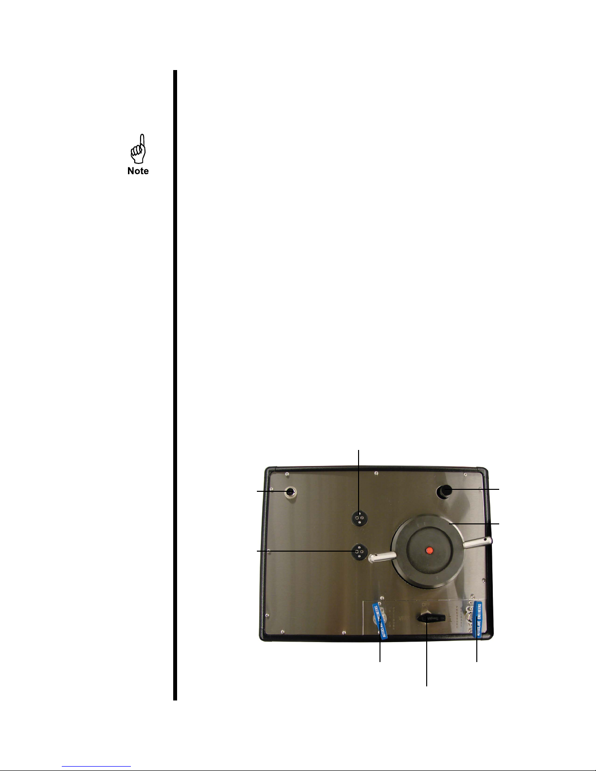
Potentiometer
Calibration
Port
Thermocouple
Port
Data Port
Air To Cylinder
Oil Reservoir
Cap
Test Cell
Pressure Release
Oil Reservoir Valve
OFITE, 11302 Steeplecrest Dr., Houston, TX 77065 USA / Tel: 832-320-7300 / Fax: 713-880-9886 / www.ote.com 5
Setup
Chart Recorder
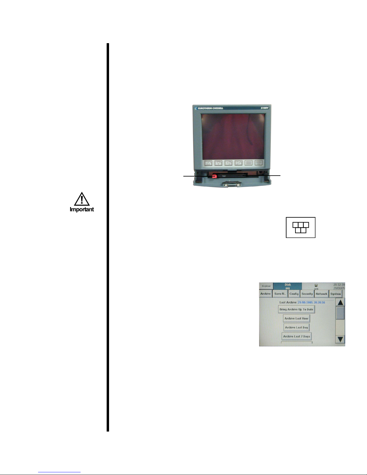
The OFITE Benchtop Consistometer includes a Eurotherm Chessell 6100A
chart recorder for displaying and recording test data. It features a removable
drive for easily transferring test data to a PC for processing. The unit is setup
to automatically record data onto the disk during the test. However, for this
feature to work, you must have the disk inserted into the drive when the unit
is powered on. Otherwise, the data must be manually archived at the end of
the test.
Eject Button
It is strongly recommended that you carefully study the Eurotherm
Chessell 6100A instruction manual before using this equipment.
To manually archive test data:
1. Press the “Root Menu” button.
2. Press “Operator” from the root menu.
3. At the top of the screen, choose “Archive” and then choose “Disk”.
Recorder Disk
Root Menu
Button
OFITE, 11302 Steeplecrest Dr., Houston, TX 77065 USA / Tel: 832-320-7300 / Fax: 713-880-9886 / www.ote.com 6
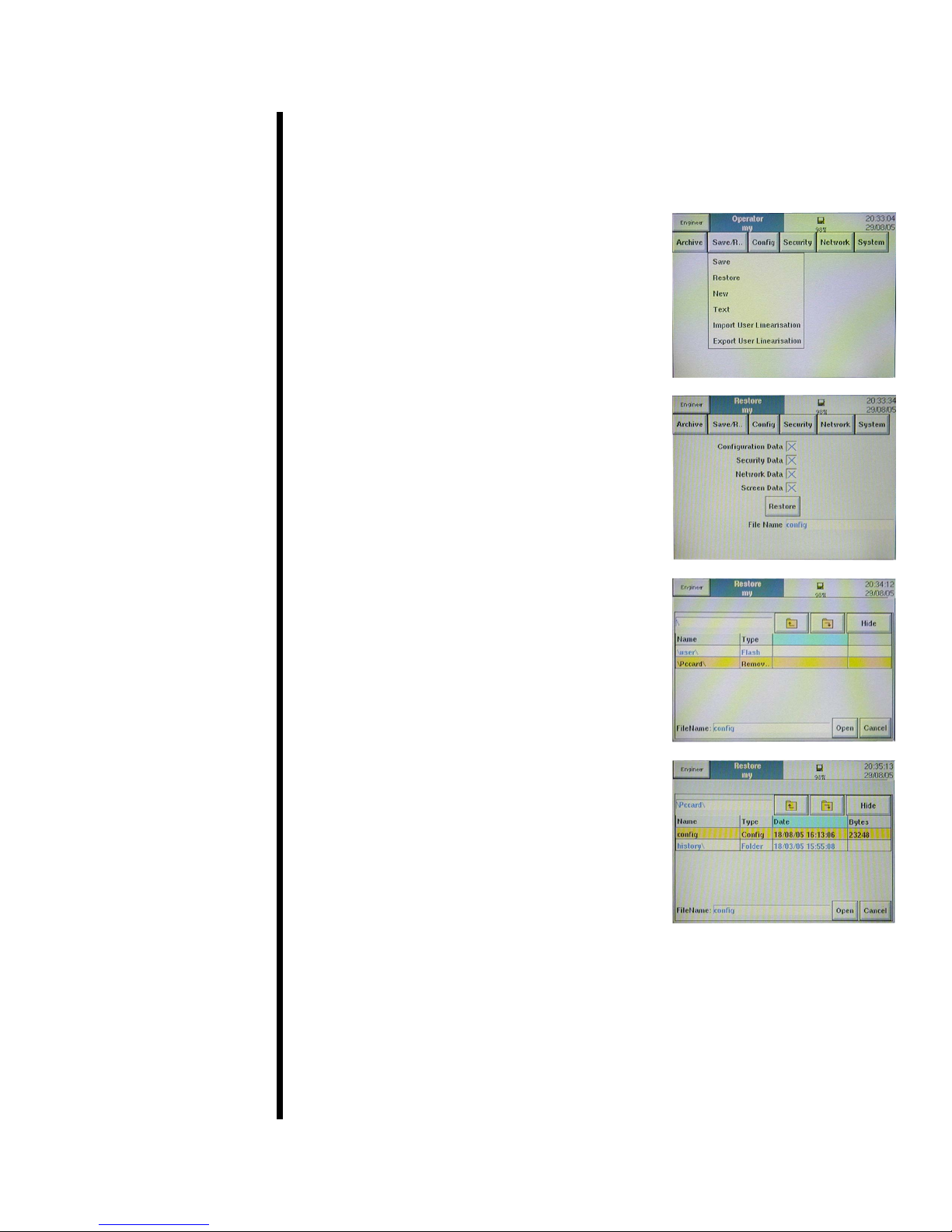
The chart recorder is shipped to you with a pre-programmed conguration
le. It is highly recommended that you do not change any of these settings.
However, in case of emergency, it is possible to restore your conguration
from the disk that is shipped with the unit.
1. At the top of the screen, press “Save/
Restore” and choose “Restore”.
2. Make sure all four options are selected,
then touch the “File Name” eld.
3. Press the up arrow to access the root
directory.
4. Select “Removable” and press the down
arrow to access the disk.
5. Choose the le titled “Cong” and press
“Open”.
6. When the progress bar at the top of the
screen stops, the restore process is
complete.
OFITE, 11302 Steeplecrest Dr., Houston, TX 77065 USA / Tel: 832-320-7300 / Fax: 713-880-9886 / www.ote.com 7

To transfer the test data to a PC:
1. Remove the disk from the chart recorder and insert it into the appropriate
drive on the PC.
2. From the Start Menu, select “Programs” then “Eurotherm” and then click
“Review”. This will open the Eurotherm Review software application.
3. From the “File” menu, select “Transfer” and then click “Files”.
4. Click the “Browse” button, then choose the appropriate drive for your
removable media. Open the “History” folder and select the les you wish
to transfer.
5. Type a name in the “Name” eld and click “OK”.
At this point you will receive a warning message. Click “OK” again.
6. When the le transfer is complete, go to the “File” menu and click “New
Chart”.
7. Click “Add Point”.
8. From the “Instrument” drop-down menu, choose the name you selected in
step 5.
9. Choose “Group 1” from the “Log Group” menu.
OFITE, 11302 Steeplecrest Dr., Houston, TX 77065 USA / Tel: 832-320-7300 / Fax: 713-880-9886 / www.ote.com 8
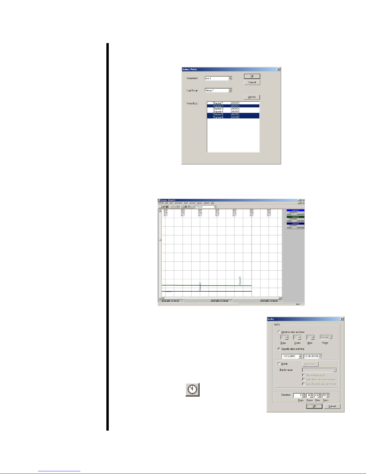
10. Now, select the Point IDs you wish to display on the chart. Hold down the
“CTRL” button to select more than one. Click “OK”.
11. The software will now create the chart based on the data collected from
the test.
12. To jump directly to a specic data point, click
OFITE, 11302 Steeplecrest Dr., Houston, TX 77065 USA / Tel: 832-320-7300 / Fax: 713-880-9886 / www.ote.com 9
the “Go To” button at the top of the screen.
Choose the data point you wish to view and
click “OK”.
Setup
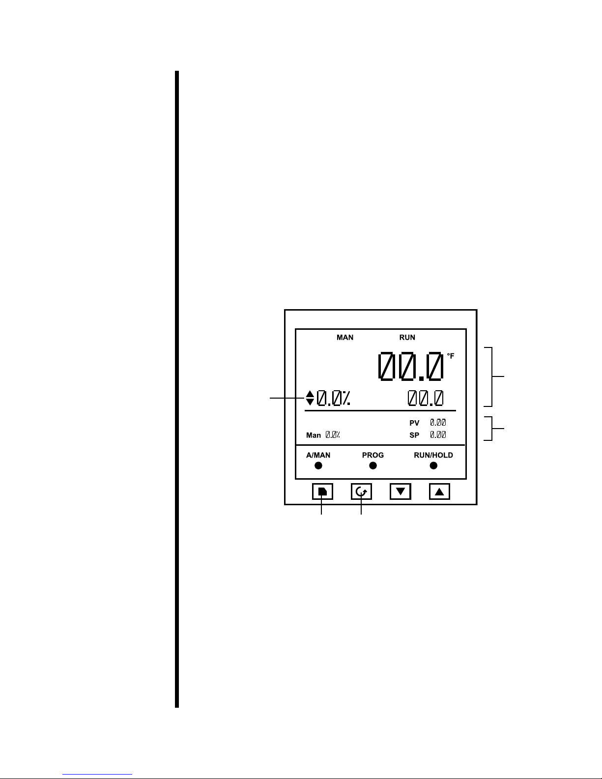
Eurotherm
The Eurotherm Model 3504 controls the temperature and displays the
pressure. When running a test with the computer, the software automatically
programs the controller. However, when running a test without the computer,
the controller must be programmed manually. It is strongly recommended
that operators carefully study the Model 3504 instruction manual before
attempting to program the controller.
When running a test without the computer, always build the program prior to
mixing the slurry and loading the slurry cup.
The Eurotherm 3504 can store up to eight custom programs. Each program
consists of multiple segments. In a segment, the temperature setpoint can be
changed or held for a certain amount of time.
Each program also can consist of two channels; one for temperature and one
for pressure. Since the Benchtop Consistometer does not offer automatic
pressure control, only Channel 1 should be programmed.
Temperature
Selector
Pressure
Page Scroll
To edit a program:
1. Press the “Page” button until the display reads “Program Edit”.
2. Use the up and down arrows to select the program you want to edit.
3. Press the “Scroll” button to move to the Channel parameter.
4. Use the up and down arrows to select Channel 1.
OFITE, 11302 Steeplecrest Dr., Houston, TX 77065 USA / Tel: 832-320-7300 / Fax: 713-880-9886 / www.ote.com 10
Programming Channel 2 is not supported on the Benchtop
Consistometer.
 Loading...