

OfiTE 120-70, 120-70-1 Instruction Manual
Stirred Fluid Loss Tester
120-70 (115 Volt)
120-70-1 (230 Volt)
Instruction Manual
Updated 2/18/2019
Ver. 8
OFI Testing Equipment, Inc.
11302 Steeplecrest Dr. · Houston, Texas · 77065 · U.S.A.
Tele: 832.320.7300 · Fax: 713.880.9886 · www.ote.com
©
Copyright OFITE 2015

Table of
Intro..................................................................................................2
Overview .........................................................................................2
Contents
Components ...................................................................................3
Specications ................................................................................4
Setup................................................................................................4
Operation.........................................................................................4
Preparing the Test Cell ................................................................4
Installing the Test Cell ................................................................. 6
Performing the Test ..................................................................... 7
Maintenance .................................................................................. 11
Diagram .........................................................................................13
Warranty and Return Policy ........................................................15
OFITE, 11302 Steeplecrest Dr., Houston, TX 77065 USA / Tel: 832-320-7300 / Fax: 713-880-9886 / www.ote.com 1

Intro
Successfully cementing the casing string of an oil or gas well is highly
dependent upon the characteristics of the cement slurry. Properties that
should be considered include consistency, density, the ability to quickly
develop compressive strength, rheological properties, and ltration control.
Well cements that have poor ltration control can lead to a complete failure
of the cementing operation. In addition, the invasion of ltrates into producing
zones causes formation damage, which can greatly reduce the production
potential of the reservoir. Developing cement slurries that have minimal
ltration loss prevents expensive remedial cementing operations and reduces
formation damage. The OFITE Stirred Fluid Loss Tester provides a reliable
means of determining the uid loss characteristics of a well cement.
Overview
A cement slurry is poured into the test cell, which is then placed into the
heating jacket. The gear drive system is connected to the agitation paddle,
which is dimensionally equivalent to an atmospheric consistometer paddle.
The desired test temperature is maintained by a digital PID temperature
controller, while the necessary pressure is applied to the cell to prevent
evaporation of the liquid phase. When conditioning the cement in accordance
to API (American Petroleum Institute) Specication 10 guidelines, the paddle
is rotated at 150 rpm for 20 minutes. Once the cement is conditioned,
differential pressure is applied to the cell. The ltrate is collected in a back
pressure receiver for 30 minutes. The API denes uid loss as the volume
(ccs) of ltrate that is collected during this 30-minute interval.
OFITE, 11302 Steeplecrest Dr., Houston, TX 77065 USA / Tel: 832-320-7300 / Fax: 713-880-9886 / www.ote.com 2

Components
Consumables:
#120-70-025 Flexiseal
#120-70-033 PTFE Sleeve Bearing, Qty: 3
#120-70-1-026 Paddle Assembly
#120-503 Paddle Pin
#165-44 High-Temperature Thread Lubricant, 1 oz
#170-18 Detachable Screen, 325 Mesh with 60 Mesh Backup
#171-11 O-ring for Backpressure Receiver
#171-190-057 Valve Stem O-ring, Viton 90D
#171-190-060 Test Cell O-ring, Viton 90D
Replaceable Parts:
#120-70-1-020 Backpressure Receiver
#120-70-1-021 Gauge, 1,000 psi
#120-70-1-022 Gauge, 4,000 psi
#120-70-1-049 Spanner Wrench
#120-70-1-062 Test Cell
#120-70-1-064 Cell Cap, Filter Side
#120-70-024 Cell Cap, Drive Side, With Paddle
#120-80-4 Temperature Controller
#120-80-6 Motor
#130-76-03 Thermocouple
#152-37 AC Power Cord, (115 Volt Only)
#152-38 AC Power Cord, (230 Volt Only)
#153-14 Graduated Cylinder, 50 mL × 1 mL, Glass
#153-16 Graduated Cylinder, 25 mL × 2/1 0 mL, Glass
#165-14-8 Type “J” Thermocouple, ⅛" × 6"
#170-16 Valve Stem, 3.25" (8.3 cm)
#170-35 6" Adjustable Wrench
#171-23-1 Safety Pin with Lanyard
115 Volt Fuses:
#121-017 Heater Fuse, 8 Amp
#130-10-503 Motor Fuse, 4 Amp
#172-09 Main Fuse, 10 Amp
230 Volt Fuses:
#121-017 Main Fuse, 8 Amp
#130-10-503 Heater Fuse, 4 Amp
#172-05 Motor Fuse, 2 Amp
Optional:
#120-71 One Year’s Spare Parts for Stirred Fluid Loss Tester
#120-70-025 Flexiseal, Qty: 4
#120-70-034 Washer, Rulon J, Qty: 8
#130-76-03 Thermocouple, Qty: 2
#153-16 Graduated Cylinder, 25 mL × 2/10 mL, Glass, Qty: 4
#170-16 Valve Stem, 3.25" (8.3 cm), Qty: 6
#170-18 Detachable Screen, 325 Mesh with 60 Mesh Backup, Qty: 12
#171-11 O-ring for Backpressure Receiver, 100 mL, Qty: 12
#171-23-1 Safety Pin with Lanyard, Qty: 2
#171-190-057 Valve Stem O-ring, Viton 90D, Qty: 50
#171-190-060 Test Cell O-ring, Viton 90D, Qty: 50
OFITE, 11302 Steeplecrest Dr., Houston, TX 77065 USA / Tel: 832-320-7300 / Fax: 713-880-9886 / www.ote.com 3
Specications
- Maximum Pressure: 2,000 psi
- Maximum Temperature: 450°F (232.2°C)
- Temperature is maintained by a PID temperature controller
- Variable paddle rotation speed (5 to 200 rpm)
- Filtration portion of cell is dimensionally equivalent to an API approved
HTHP test cell
Setup
Operation
Preparing the Test Cell
1. Connect the instrument to a power source. Be sure to use the correct
voltage for your equipment.
2. Connect the instrument to a nitrogen source using the connector on the
back panel. The nitrogen source should be regulated between 2,000 and
2,500 psi.
3. Connect a drain and water supply to the back of the unit. All connectors
are ¼" NPT.
1. Begin by turning the test cell so that the end labeled "In" is facing up.
2. Apply high-temperature grease (#165-44) to a cell cap o-ring (#171-190-
060) and insert it into the groove inside the test cell.
3. To facilitate cleaning, a thin coat of white lithium high-temperature grease
may be applied to all surfaces that will come in contact with cement. This
includes the inside of the test cell, the paddle, and the inside surfaces of
the two cell caps.
4. Lubricate the threads on the paddle assembly cell cap. Press the poppet
valve into the closed position and insert the paddle into the test cell. Hand
tighten completely.
5. Screw the valve stem (#170-16) into the paddle assembly cell cap and
tighten it completely.
6. Turn the cell over. If possible, place the cell in a vise to prevent damage
to the valve stem.
7. Mix your cement slurry as directed in API
Specication 10 and pour no more than 425
mL into the test cell. Remove any cement
from the o-ring groove.
8. Apply high-temperature grease to another
cell cap o-ring (#171-190-060) and place it
in the groove inside the end of the test cell.
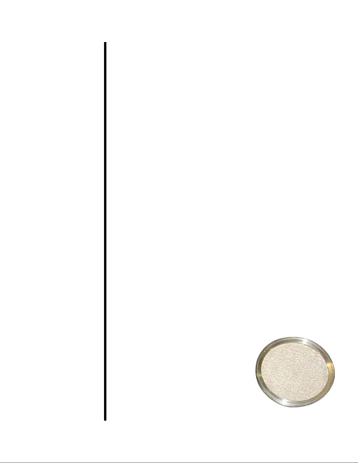
Cement Screen
OFITE, 11302 Steeplecrest Dr., Houston, TX 77065 USA / Tel: 832-320-7300 / Fax: 713-880-9886 / www.ote.com 4
 Loading...