

INSTRUCTIONS
for installation and use
WND 040
WINE DISPENSER FOR
RESIDENTIAL AND PROFESSIONAL USE

How to use this manual
Thank you for choosing this innovative product.
These machines for pouring wine offer high quality and
characteristics of refrigeration based on the most advanced
technologies offered by the market.
This manual has been specially designed to guide you through the
functions and features of the Wineemotion dispenser.
Please read carefully
• Read all safety precautions in this manual
before using the dispenser to ensure a safe and proper use.
• The descriptions in this manual are based on default settings of dispensers.
• Images and screenshots used in this manual may differ from the actual product.
• The contents of this user manual may differ from the product or software from the manufacturer and are subject to modifications without
prior notice.
• The features and additional services may vary depending on
available dispenser or software.
• Wineemotion is not liable for performance issues or incompatibilities
caused by changing the settings of the machine or operating system
software, or when the machine is placed in environmental settings
that differ from recommendations contained in this manual.
Ofcine Gullo
2

The attempt to customize the system or alter either the electronics,
mechanical parts, or software could cause malfunction of the dispenser and the loss of warranty.
• You can check for software updates for the dispenser by visiting Wineemotion (www.wineemotion.com/upgrades).
• This dispenser supports services and applications that may require an
active data connection for its operation and updating.
• Keep this manual for future reference.
3
Ofcine Gullo
Information icons
To begin, please familiarize yourself with the icons used in this manual:
Warning - Situations that could cause problems in the proper
functioning of the system.
Caution - Situations that could cause damage to the device or
person.
Note - Notes, operational tips, or additional information.
Reference - Indicates where additional related information can
be found. For example, Chap. 1 (meaning "refer to
Chapter 1 ").
Followed by - Indicates in which order you must select the
options or menus to perform a step. For example:
In the Control Panel , select the Calibrating Menu
►
→
►
►
→
Ofcine Gullo
4

Manual of Use
1
Table of contents
1. Guidelines for reading the manual
2. Machine identication
2.1 Service request
2.2 Attached documents
. General description
4. Technical information
4.1 Dispenser overview
5. Technical data
5.1 Included Accessories
6. Safety information
6.1 General notes on safety
6.2 Environmental eects, safety warnings
7. Information on transport and storage
7.1 Packing and unpacking
7.2 Transport and storage
7.3 Transferring and Lifting
7.4 Checklist content "check integrity dispenser"
8. Installation
8.1 Installation position in cabinetry
8.2 Installation with encased positioning and multiple machines
8.3 Installation ush with front closure
8.4 Power supply
8.5 Pneumatic system
(for dispenser with external cylinders)
8.5.1 Pneumatic system (for dispensers with internal cylinders)
8.6 Climate controlled machines
5
Ofcine Gullo

2
8.7 Refrigeration system
8.8 Argon gas supply
8.9 Compressed air supply
8.10 Warning labels
8.11 Installation and replacement of cylinders
(mod. with internal cylinders)
8.11.1 Installation and replacement of cylinders
(mod. with external cylinders)
8.11.2 Connections
9. Operation
9.1 The front door
9.2 Suction tube
9.3 Piston components for bottle positioning
9.4 Correct positioning of the bottle
10. Dispensing
11. Display and visualization of the system
14.1 Error states of the system
12. Menu description
14.1 How to interact with the display
13. Operation from the main main
13.1 Calibrating
13.2 Display setting
13.3 Wine setting
13.4 Fridge setting
14. Maintenance and cleaning
14.1 Minimum qualication of personnel
14.2 Daily maintenance
14.3 Periodic maintenance
Ofcine Gullo
6

Manual of Use
3
14.4 Extraordinary maintenance
14.5 Special arrangements for troubleshooting
14.6 PPE required for maintenance personnel
14.7 Precautions for maintenance
15. Disposal of the machine
16. Declaration of compliance
17. Machine warranty
10. Certications held by SERIES 3 Dispensers
19. Authorized cleanind products
19.1 SaniPack MP 100
19.2 SaniKleen 512 WE
7
Ofcine Gullo
4
This manual is a guide for the use of the machine, please read it carefully
before unpacking the machine, as it contains important information
on safety at all stages of life of the machine, moving, unpacking,
installation, commissioning in service, operation, maintenance and
disposal of the machine.
If you are unsure about the correct interpretation of the
instructions, contact the manufacturer to obtain the necessary
clarications.
READ THE MANUAL BEFORE YOU UNPACK THE MACHINE.
KEEP THIS MANUAL WITH THE MACHINE.
1. Guidelines for reading the
manual
Ofcine Gullo
8
Manual of Use
5
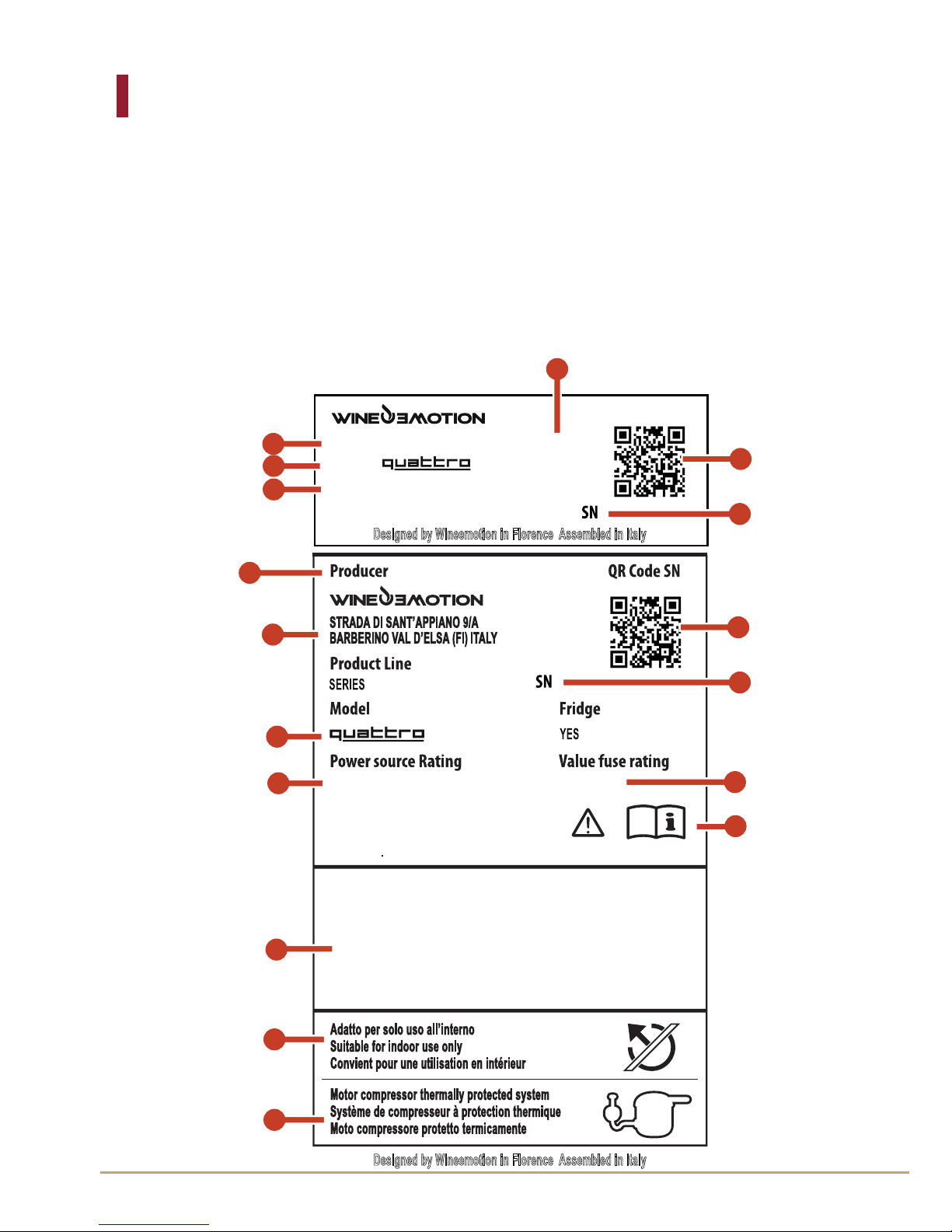
2. Machine Identication
Each machine Wineemotion has an identication plate which shows
the company's data, the serial number of the machine, and the
electrical and pneumatic specications.
The plate should not be removed as it is useful to the service center
and Wineemotion to go back to the machine specications. The plate
is present in the certicate of conformity.
An example of the plate is shown below.
Designed by Wineemotion in Florence Assembled in Italy
CB
QR Code SN
Designed by Wineemotion in Florence Assembled in Italy
Series: SERIES2 Fuse:
2 x FX2,5A
Model:
Power Source Raiting
220 Vac 50 - 60Hz 0,6 A
1
12
2
13
11
3
5
6
4
14
15
7
8
9
10
16
17
220 Vac 50 - 60Hz 0,6 A
Fridge is climatic class N
power consuming 130W
2 x FX2,5A
2
9
Ofcine Gullo
6
9
10
Power source rating
Value fuse rating
►
Chap. 5
See manual for detailed information
QR code
11
12
Number Function
1
2
3
Manufacturer identification
Serial number
Manufacturer information
4
5
6
Reference mark initials for compliance with
national regulations
Model
Voltage, frequency and intensity
7
Product line
8
Model
Value fuse rating
►
Chap. 5
13
Warning: this machine is for indoor use only.
- This label reminds the user that the dispenser
is to be used only indoors and away from
atmospheric agents that may damage it.
Motor compressor thermally protected
system.
14
15
QR code
Serial number
16
17
Ofcine Gullo
10

Manual of Use
7
2.1 Service Request
If necessary, please contact the support team, or authorized
technicians.
If technical assistance is required, please always provide the
identication data on the label and details of any malfunctions that
have occurred. You can nd an up-to-date list of authorized service
centres on the www.wineemotion.com/assistance/ page.
2.2 Attached Documents
The following documentation is provided with this manual.
• EC Declaration of Compliance
• CB Declaration of Compliance
• Declaration of cETLus (U.S., Canada) compliance
•Warranty Statement
3. Overview
This wine dispenser is a machine designed for the preservation of the
wine from both an organoleptic and temperature perspective.
The presence of a controlled atmosphere of nitrogen or argon allows a
prolonged preservation to a maximum of 20 days.
The operating temperature of the machine is adjustable allowing you
to serve both white and red wines under optimum conditions.
Listening to our customers has helped Wineemotion develop a
product using materials and components that meet strict international
requirements in terms of safety and hygiene.
The image on the next page shows all the machine's features in detail.
Most of the aesthetic design details can be customized with dierent
types of materials and colours, thus giving customers the chance to
customise its look to match their needs.
For the current list of models and variants please visit www.
wineemotion.com
11
Ofcine Gullo

8
4.1 Dispenser overview
• The Wineemotion dispenser is designed and manufactured to pour
and enjoy high-quality wines by the glass.
The main feature of the dispensers is not to alter the taste of the wine,
followed by these main objectives:
1. Preserve the scent and avors
2. Prevent oxidation
3. Avoid waste
4. Control the temperature
• The dispenser is equipped with a cooling unit, ideal for the storage of
white and rosé wines.
• The dispenser has a control panel with push buttons, from where you
can choose the wine and the desired portion to be dispensed as well
as change the system settings.
• Images and descriptions in this manual refer to WINEEMOTION Dispenser Series 2.
• The Wineemotion dispenser can be used for small, medium or large
installation, for behind the bar or self service in restaurants, wine bars,
casinos etc.
• Please refer to the "Technical Data" section for more details on dimensions and technical specications of the dispenser as well as for the
precise installation notes and necessary prerequisites.
4. Technical Information
Ofcine Gullo
12
Manual of Use
9
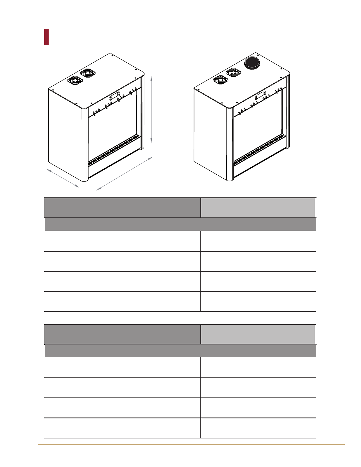
5. Technical data
A
P
L
4 BottlesModel with external cylinders
Height (H)
Length (L)
Depth (D)
566
550
320
Weight (Kg)
45
Dimensions (mm)
4 BottlesModel with internal cylinders
596
550
320
45
Dimensions (mm)
Height (H)
Length (L)
Depth (D)
Weight (Kg)
13
Ofcine Gullo

10
Nitrogen pressure with internal reg.
3-5 bar
Compressed air pressure 5 - 8 bar
Refrigerant used
R134A
Max cooling circuit pressure
10 bar
Nitrogen pressure with external reg.
max 200 mbar
Height
Maximum diameter
mm
mm
280÷355
100
4Model
Voltage (USA -Canada )
Frequency
Max power draw refrigerated
110V
50-60 Hz
130 W
4 BottlesDescription
Bottle specifications
Unit Description
Ambient temperature
Maximum relative humidity (Rhu)
Measurement
°C
Rhu
15÷27
70%
Installation environment specifications
Electrical Characteristics
Max power draw ambient temperature
50 W
Voltage EU
220V
Fuses for USA and Canada
F 4A
Fuses for Europe
F2.5A
Ofcine Gullo
14

Manual of Use
11
5.1 INCLUDED ACCESSORIES
The distributor is supplied with the following accessories:
→ copy of the installation manual paper or digital
→ warranty and compliance certificate
→ suction tubes
Any other accessories can be supplied in special versions.
15
Ofcine Gullo

12
6.1 General Safety Warnings
• The manufacturer, in the design and manufacture of regulators, is to
foresee and avoid risks to your health. The manufacturer realizes in full
compliance with the laws and materials at its disposal the know-how
in the design and implementation of the distributor. This information
warns users about possible risk behavior and how to avoid them. However, the precautionary information is essential and mandatory. The
safety also depends on the users.
Before turning on the dispenser for the rst time is strongly recommended to read this manual to fully understand the contents, especially the safety instructions.
• Taking some time to read and understand the contents of this manual will help you avoid hazardous conditions and abnormal behavior.
It would be too late to do what should have been done in case of an
accident.
• When lifting, follow the instructions for movement of the dispenser
on the packaging and in the manuals supplied.
• Pay attention to the symbols on the labels, shapes and colors refer to
important safety notices. Maintaing in good condition.
• Only persons who have read and understood the contents of the manual are allowed to use the dispenser.
• The dispenser must be installed in a dry environment provided sucient ow of 'fresh air according to the manufacturer's specications.
Environment Data
Ambient temperature Duty ° C 15 ÷ 27
Maximum relative humidity (Rhu) 70% Table 1: Technical data Dispensers
Description Unit Value
• The dispenser must be used according to the intended purpose only.
Improper use or misuse can lead to conditions of risk and economic
damage.
6. Safety information
Ofcine Gullo
16

Manual of Use
13
• When you use the dispenser, please make sure that there are no potential risks to health and safety, particularly for children and the disabled.
• Do not change any device / component inside the machine. Any service not described in this manual should be performed by qualied
personnel, in particular, authorized by the manufacturer.
Use only original spare parts.
• Keep the nozzle in perfect maintenance and perform maintenance as
described in this manual.
Good maintenance will keep the regulator working perfectly for a long
time and maintain high safety standards.
• Never wash the dispenser or direct jets of water to the parts inside or
outside of it, so as to prevent damage and / or damage to electronic
devices. Do not perform any maintenance if the regulator is powered
up or before removing the power cord. Make sure that it stays disconnected until the end of the service.
• The power cord should be carefully positioned to avoid interference with the person; to prevent general damage ensure that the cable
stays away from hot surfaces.
• Do not operate the machine in the event of a damaged power plug
or power cord.
• Never clean the dispenser with corrosive or abrasive materials, with
particular attention to the surfaces of the keyboard and the front glass,
which, being made of plastic materials, can scratch and need special
care to clean them. Refer to the appropriate chapter for specic machine cleaning techniques and products to use
• Never plug the power cord if the electrical characteristics of the dispenser does not match the voltage / frequency / power provided by
the manufacturer.
• Before you leave and, after leaving the distributor out of service for a
long time, always perform maintenance to ensure hygienic conditions.
• Do not install the regulator in critical environments at risk of explosion and re, next to heat sources or rooms with the risk of food contamination. The regulator should not be exposed to weather or corrosive
fumes.
17
Ofcine Gullo

14
6.2 Environmental eects, safety warnings
• Every organization has to apply specic procedures to estimate
the eects of its activities (Goods, services, etc.) may have on the
environment.
• The procedure to identify the signicant environmental eects, must
take into account the following elements:
Discharge
Drainage
Disposal
Mass pollution
Commodities and natural resources
Environmental eects, local issues
• All components of the package must be disposed of in accordance
with applicable laws.
• During installation the environment must be supplied with ducts for
hot air exhaust and to ensure fresh air for operation.
• During operation and maintenance, do not to dispose of degraded
products (oil, grease, etc.) into the environment, store the components
and dispose of in compliance with federal regulations.
• Keep the noise level to a minimum to reduce noise pollution.
• During the removal, store the components on the basis of the
chemical properties and dispose of in accordance with applicable law.
• In compliance with the law for WEEE (Waste Electrical Appliances
Electronics), the dispenser must be disposed separately from all
electrical and electronic components and specify the areas of
collection, or return the dispenser to the local distributor for credit
towards the rate of a new purchase.
• All components of the dispenser having dierent chemical
characteristics should be disposed of separatel.
Ofcine Gullo
18
Manual of Use
15
Illegal disposal of WEEE materials listed
in the law will be punished by local law
where the crime is committed.
19
Ofcine Gullo
16
7. Transport and storage
information
7.1 Packaging and unpacking
• The machine is packed in a cardboard box protected by an elastic
film. When unpacking, carefully extract the dispenser and check that
it is complete.
If any parts are damaged or missing, do not install the dispenser and
contact an authorized dealer to resolve the problem.
• Important: information about the safe transfer of the dispenser can
be found on the packaging.
The package must be disposed of according to applicable laws and
regulations.
Keep the box in case the machine needs to be transported to another
location in future.
CAUTION: DURING TRANSIT, DO NOT TILT THE
DISPENSER HORIZONTALLY. ENSURE IT IS KEPT UPRIGHT
AS SHOWN ON THE PACKAGING.
Ofcine Gullo
20
Manual of Use
17
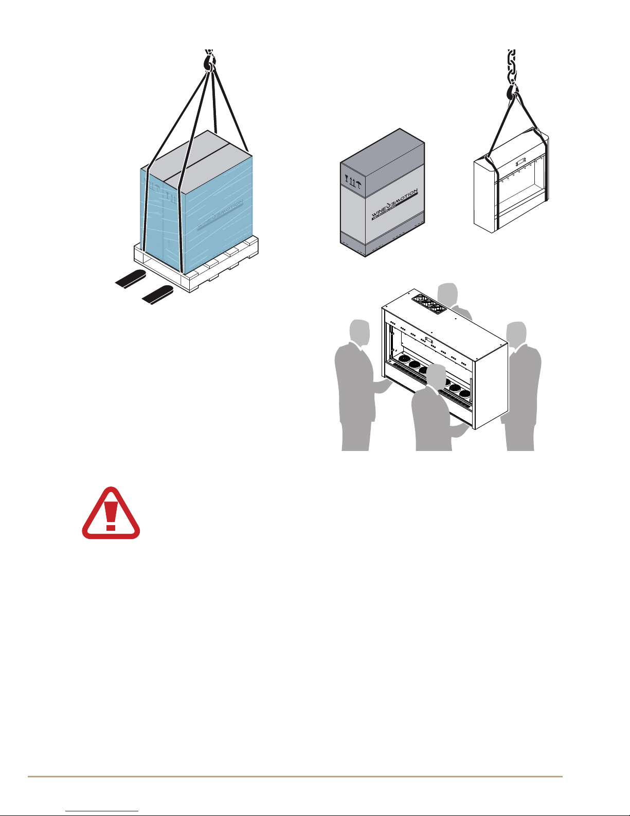
7.3 Moving and lifting
The dispenser may be moved, if placed on a platform, using forklifts,
(manual or automatic); or with straps, making sure these are secured
carefully to ensure even weight distribution prior to lifting.
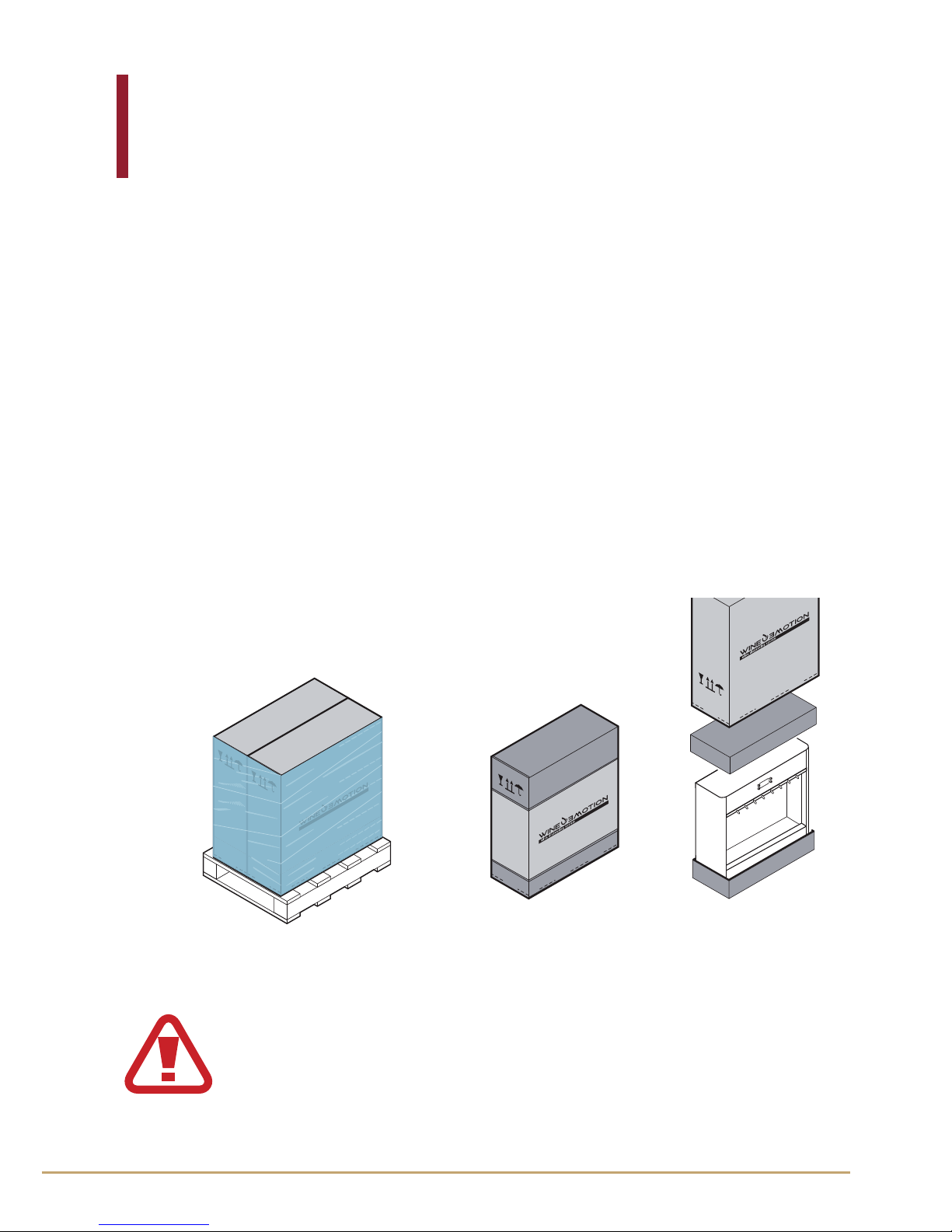
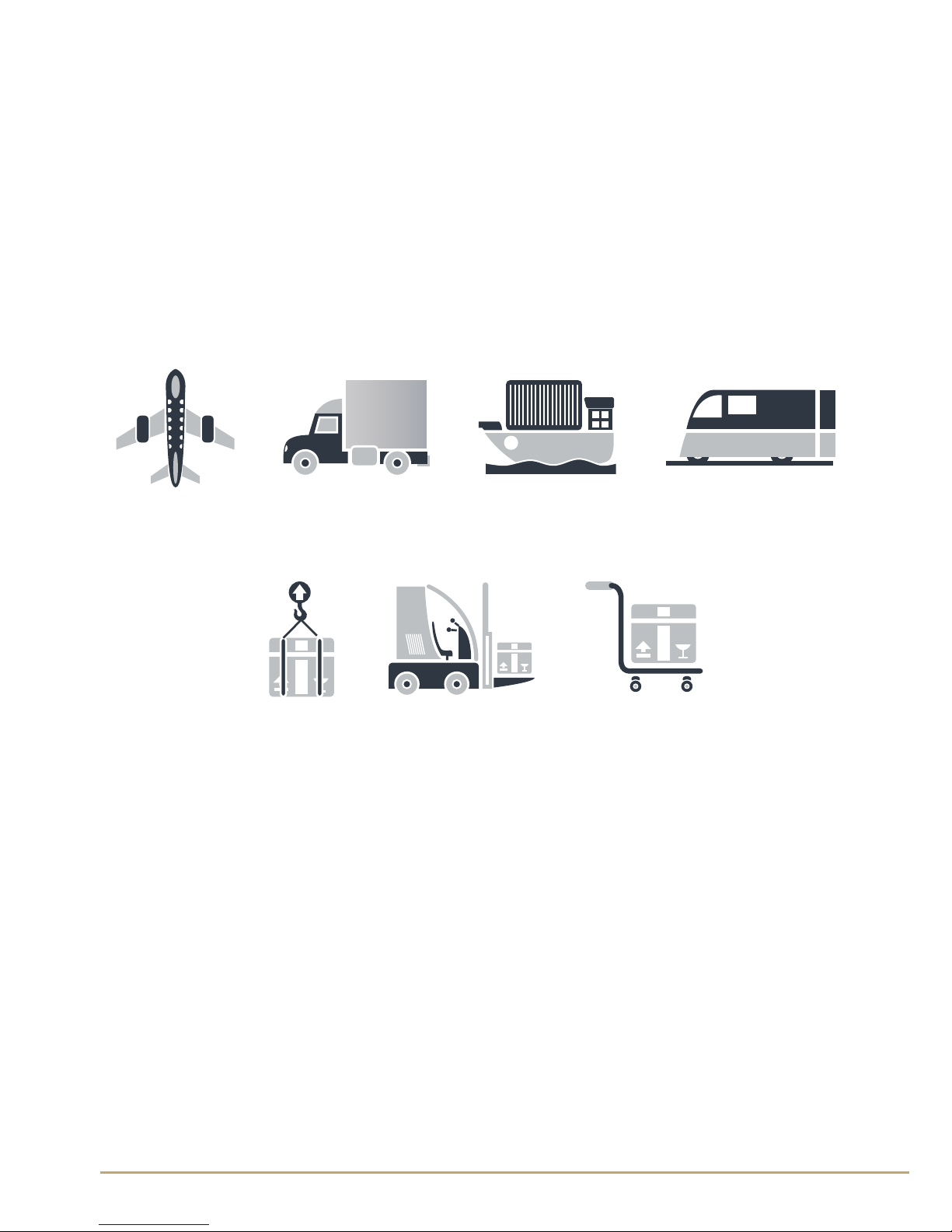
7.2 Transport and storage
• The dispenser can be transported using dierent methods. The
following diagram shows the most common solutions.
• In order to protect the dispenser during transport, check the
packaging is as specied in
►
Chapter 7.1.
• If the dispenser is to be installed some time after its delivery, it will be
necessary to store it in a dry place with a temperature between 0° and
40°.
Transports methods
Handling methods
21
Ofcine Gullo
18
The illustrations demonstrate the movement and most suitable lifting methods.
7.4 "Dispenser integrity check" content checklist
•Each consignment includes a checklist with reporting documents and
descriptions.
• When you receive the checklist, refer to the "package contents" to
check the box numbers and ensure everything has been delivered.
If any components are damaged or missing, do not install the dispenser.
Contact an authorized dealer to resolve the problem.
It is recommended to lift the machine by mechanical
means, or with at least four persons, in compliance with
the current regulations on accident prevention
Ofcine Gullo
22
Manual of Use
19
50 20 20
150 150
900÷1000
A
450
B
50 20 20
400
450
B
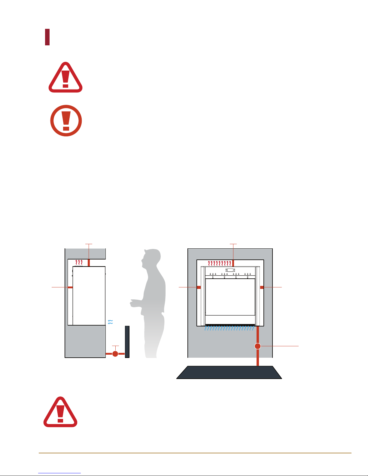
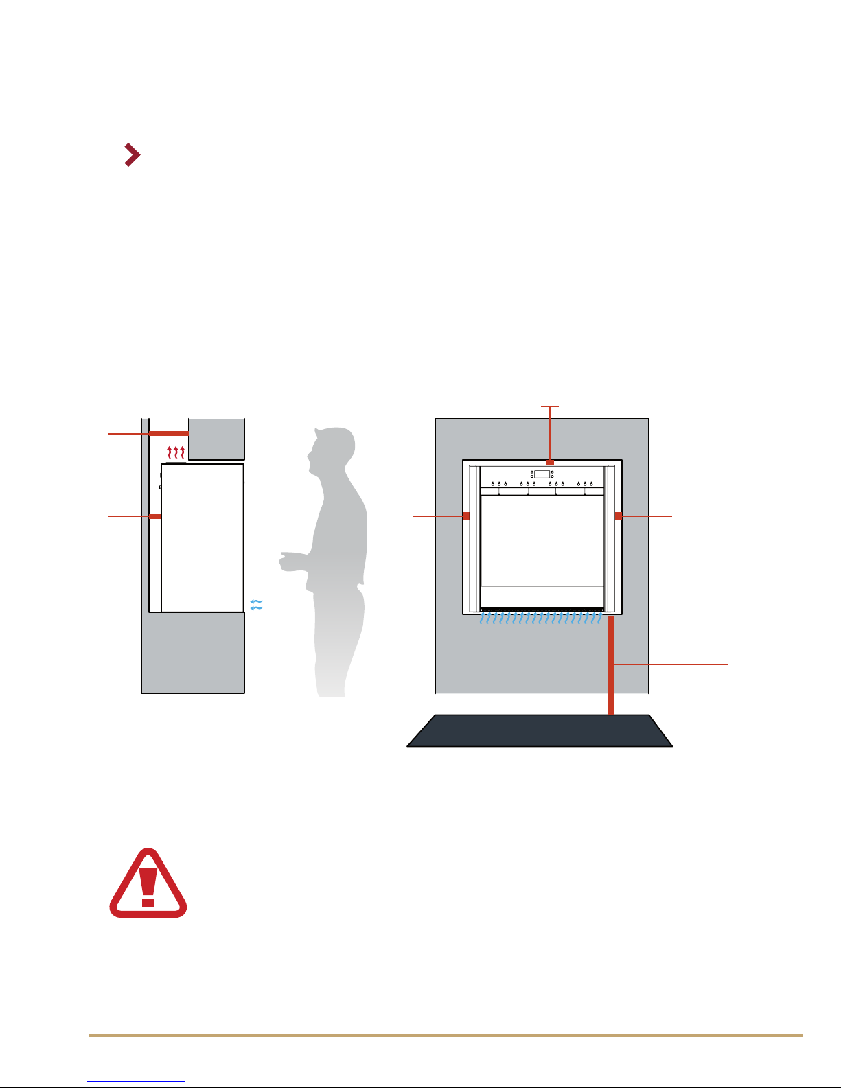
8. Installation
8.1 Recessed installations
The distance shown in the diagram is the recommended distance from
the oor, which must be 900 or 1000 mm. The distance B is the minimum
distance recommended for the exhaust: 450 mm. The spaces shown in
the diagram should not be covered up as they provide ventilation of
the machine.
WARNING: THE MACHINE MUST ALWAYS BE
HORIZONTAL POSITION
To not have danger or instability of the equipment you
need to successfully perform the procedures in this
manual.
The air intake zone marked
50 20 20
20 20
150 150
900÷1000
900÷1000
163
50
20
A
450
B
20 20
900÷1000
200
50
20
50 20 20
400
400
900÷1000
A
450
B
C
A
B
must be clear for the
proper operation of the dispenser. After use, the dispenser
exhausts hot air from the top marked
20 20
900÷1000
900÷1000
20
A
450
B
20 20
900÷1000
200
50
20
50 20 20
400
400
900÷1000
A
450
B
C
A
B
23
Ofcine Gullo
20
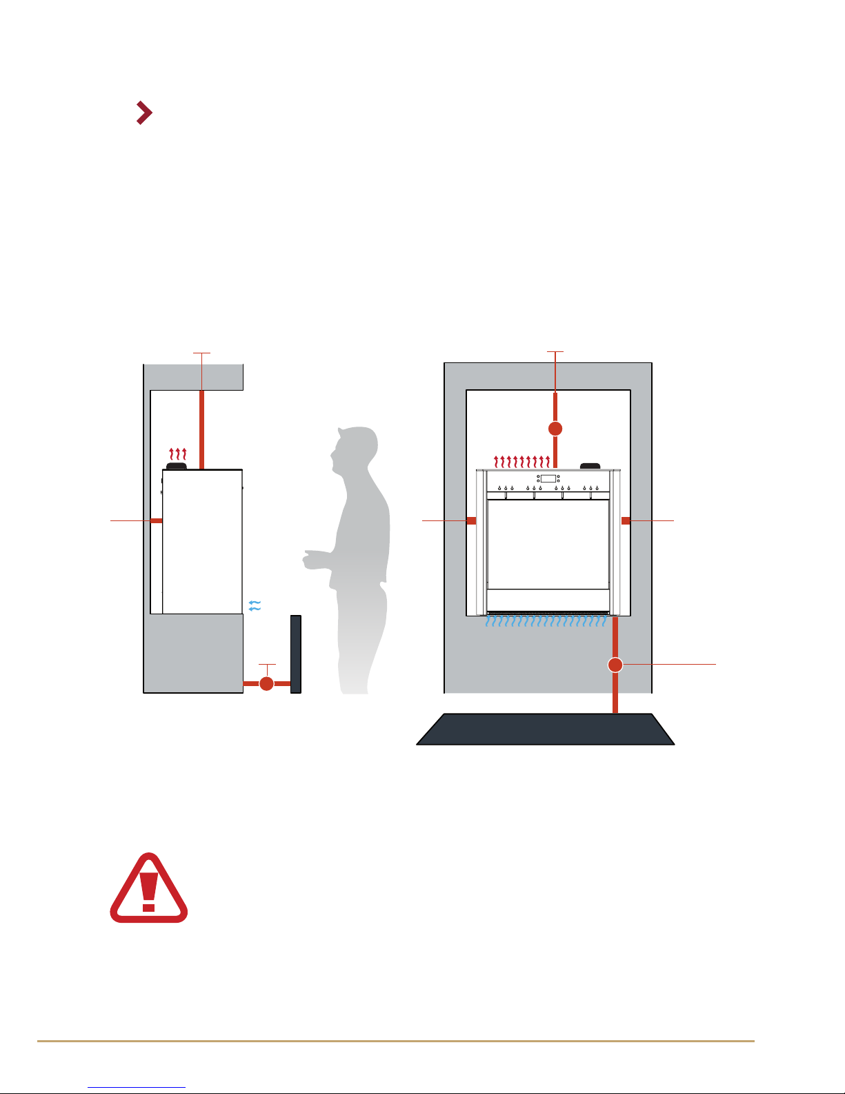
FOR DISPENSERS WITH INTERNAL CYLINDERS
The distance A shown in the gure is the recommended distance from
the oor that may be 900 to 1000 mm. The distance B is the minimum
distance for dispensing, 450mm, while the distance C is the minimum
recommended distance of 400mm for the correct insertion of the gas
into the dispenser. The spaces shown in the gure should not be closed
because they serve for ventilation of the machine.
50 20 20
400
400
900÷1000
A
450
B
C
The air intake zone marked
50 20 20
20 20
150 150
900÷1000
900÷1000
163
50
20
A
450
B
20 20
900÷1000
200
50
20
50 20 20
400
400
900÷1000
A
450
B
C
A
B
must be clear for the
proper operation of the dispenser. After use, the dispenser
exhausts hot air from the top marked
20 20
900÷1000
900÷1000
20
A
450
B
20 20
900÷1000
200
50
20
50 20 20
400
400
900÷1000
A
450
B
C
A
B
Ofcine Gullo
24
20 20
900÷1000
200
50
20
50 20 20
400
400
900÷1000
A
450
B
C
A
B
20 20
900÷1000
200
50
20
50 20 20
400
400
900÷1000
A
450
B
C
A
B
Manual of Use
21
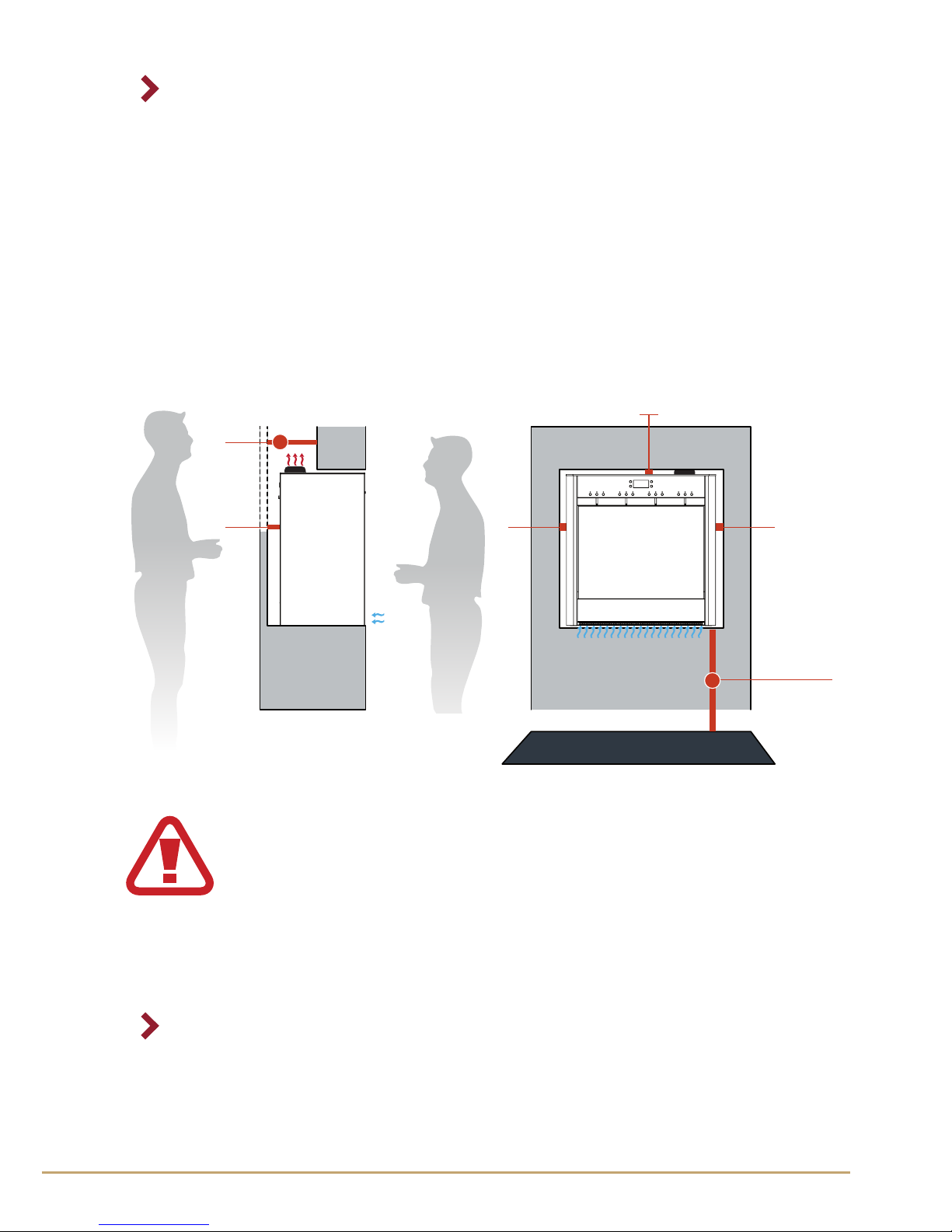
8.2 Installation with encased positioning and
multiple machines
FOR DISPENSERS WITH EXTERNAL CYLINDERS
When installing in a recessed structure please provide 163mm of
clearance on the back for the ventilation of the machine
This space must be open for the free passage of air.
The distance A shown in the gure is the recommended distance from
the oor that may be 900 to 1000 mm. The distance B is the minimum
distance for dispensing, 450mm.
50 20 20
20 20
150 150
900÷1000
900÷1000
163
50
20
A
450
B
200
50
50 20 20
400
B
The air intake zone marked
50 20 20
20 20
150 150
900÷1000
900÷1000
163
50
20
A
450
B
20 20
900÷1000
200
50
20
50 20 20
400
400
900÷1000
A
450
B
C
A
B
must be clear for the
proper operation of the dispenser. After use, the dispenser
exhausts hot air from the top marked
20 20
900÷1000
900÷1000
20
A
450
B
20 20
900÷1000
200
50
20
50 20 20
400
400
900÷1000
A
450
B
C
A
B
25
Ofcine Gullo
22
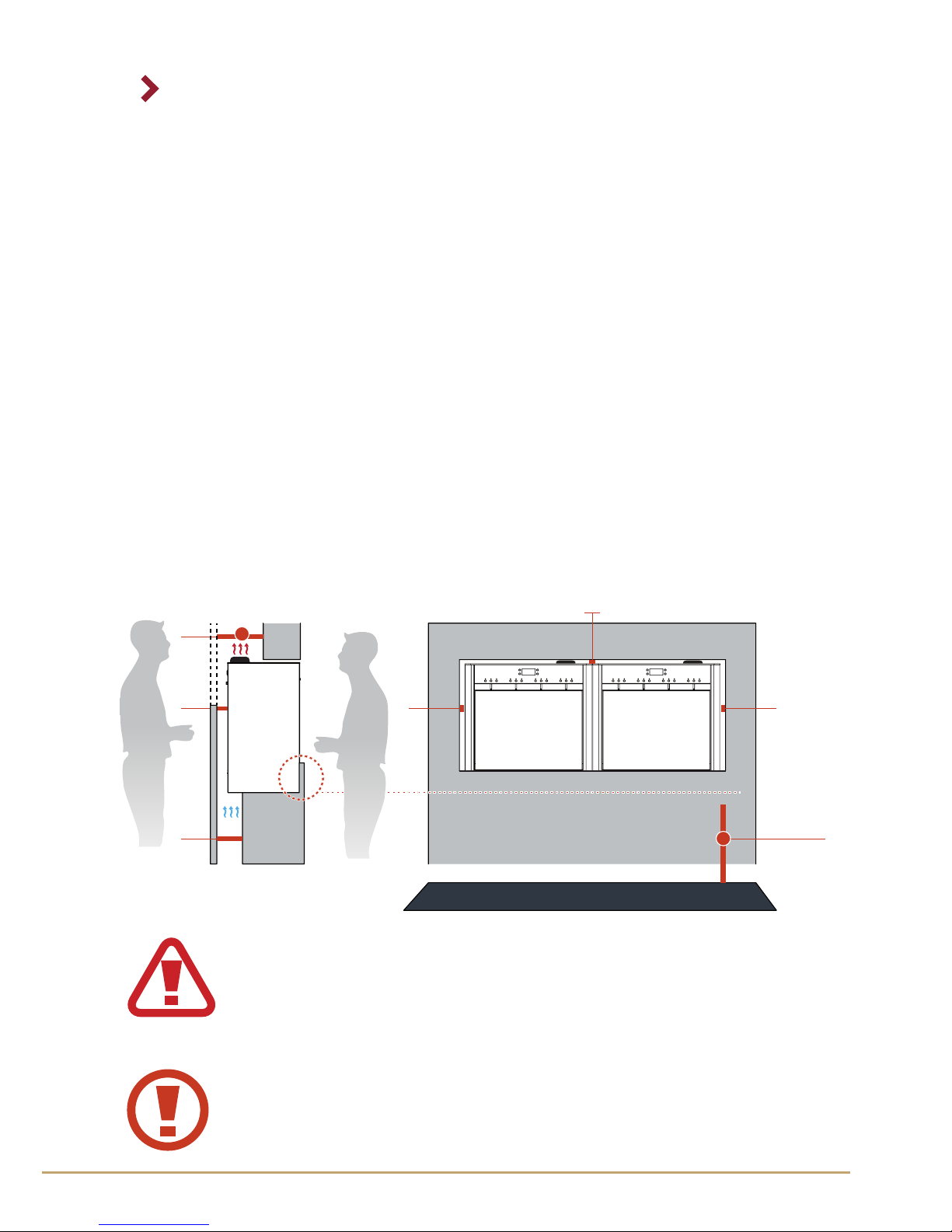
8.3 Installation ush with front closure
FOR DISPENSERS WITH EXTERNAL CYLINDERS
When you close the machine front you must create an opening on the
back, at the bottom, as the air is now drawn from the bottom instead
of the frontal zone.
FOR DISPENSERS WITH INTERNAL CYLINDERS
When installing in a recessed structure please provide 200mm of
clearance on the back for the ventilation of the machine and extraction
of the gas cylinder.
This space must be open for the free passage of air and must have
access to exchange the cylinder.
The distance A shown below is the recommended distance from the
oor that can be 900 or 1000mm. The distance B is the minimum
distance for the cylinder extraction which is 200mm.
20 20
900÷1000
200
50
20
50 20 20
400
400
900÷1000
A
450
B
C
A
B
The air intake zone marked
50 20 20
20 20
150 150
900÷1000
900÷1000
163
50
20
A
450
B
20 20
900÷1000
200
50
20
50 20 20
400
400
900÷1000
A
450
B
C
A
B
must be clear for the
proper operation of the dispenser. After use, the dispenser
exhausts hot air from the top marked
20 20
900÷1000
900÷1000
20
A
450
B
20 20
900÷1000
200
50
20
50 20 20
400
400
900÷1000
A
450
B
C
A
B
Ofcine Gullo
26

20 20
900÷1000
200
50
20
50 20 20
400
400
900÷1000
A
450
B
C
A
B
20 20
900÷1000
200
50
20
50 20 20
400
400
900÷1000
A
450
B
C
A
B
Manual of Use
23
The opening of 136mm shown in the gure is the maximum that can
be done. The distance A shown in the gure is the recommended
distance from the oor that can be 900 to 1000mm. The distance B is
the minimum distance for dispensing which is 450mm.
The space C is for the front closure to be ush with the front panel and
must have a height of 146mm.
There being a radius of curvature on the front plate from a hygienic
point of view it is good to make the panel 2mm to 144mm or less,
otherwise you risk a deposit of dirt in 'space between the panel and
the radius of curvature space.
It is always best to ask for updates measurements and technical
specications from the Wineemotion oce as technical specications
and clearance requirements can change with model revisions.
20 20
900÷1000
200
136
50
20
B
A
CAUTION: DO NOT BLOCK THE FRONT BASE OPENING;
THIS LOCATION WAS DEVOTED FOR AIR INTAKE. IF YOU
BLOCK THE FRONT OPENING, YOU MUST PROMIDE AN
OPENING FOR REAR VENTILATION.
The air intake zone marked
50 20 20
20 20
150 150
900÷1000
900÷1000
163
50
20
A
450
B
20 20
900÷1000
200
50
20
50 20 20
400
400
900÷1000
A
450
B
C
A
B
must be clear for the
proper operation of the dispenser. After use, the dispenser
exhausts hot air from the top marked
20 20
900÷1000
900÷1000
20
A
450
B
20 20
900÷1000
200
50
20
50 20 20
400
400
900÷1000
A
450
B
C
A
B
27
Ofcine Gullo
24
FOR DISPENSERS WITH INTERNAL CYLINDERS
When you close the machine front you must create an opening on the
back, at the bottom, as the air is now drawn from the bottom instead
of the frontal zone. The opening of 136mm shown in the gure is the
maximum that can be done. The distance A shown in the gure is the
recommended distance from the oor that can be 900 to 1000mm.
The distance B is the minimum distance recommended to facilitate air
ventilation and the extraction of the cylinder which is 200mm.
The space C is for the front closure to be ush with the front panel and
must have a height of 146mm.
There being a radius of curvature on the front plate from a hygienic
point of view it is good to make the panel 2mm to 144mm or less,
otherwise you risk a deposit of dirt in 'space between the panel and
the radius of curvature space.
It is always best to ask for updates measurements and technical
specications from the Wineemotion oce as technical specications.
and clearance requirements can change with model revisions
20 20
900÷1000
200
136
50
20
B
A
CAUTION: DO NOT BLOCK THE FRONT BASE OPENING; THIS LOCATION WAS
DEVOTED FOR AIR INTAKE. IF YOU BLOCK THE FRONT OPENING, YOU MUST
PROMIDE AN OPENING FOR REAR VENTILATION.
The air intake zone marked
50 20 20
20 20
150 150
900÷1000
900÷1000
163
50
20
A
450
B
20 20
900÷1000
200
50
20
50 20 20
400
400
900÷1000
A
450
B
C
A
B
must be clear for the
proper operation of the dispenser. After use, the dispenser
exhausts hot air from the top marked
20 20
900÷1000
900÷1000
20
A
450
B
20 20
900÷1000
200
50
20
50 20 20
400
400
900÷1000
A
450
B
C
A
B
Ofcine Gullo
28
20 20
900÷1000
200
50
20
50 20 20
400
400
900÷1000
A
450
B
C
A
B
20 20
900÷1000
200
50
20
50 20 20
400
400
900÷1000
A
450
B
C
A
B
Manual of Use
25
P
L
Ingressi gas
Evaporazione condensa
Alimentazione
Scarico aria calda
(Superficie calda)
2x3ARUL
*
2
3
1
OR
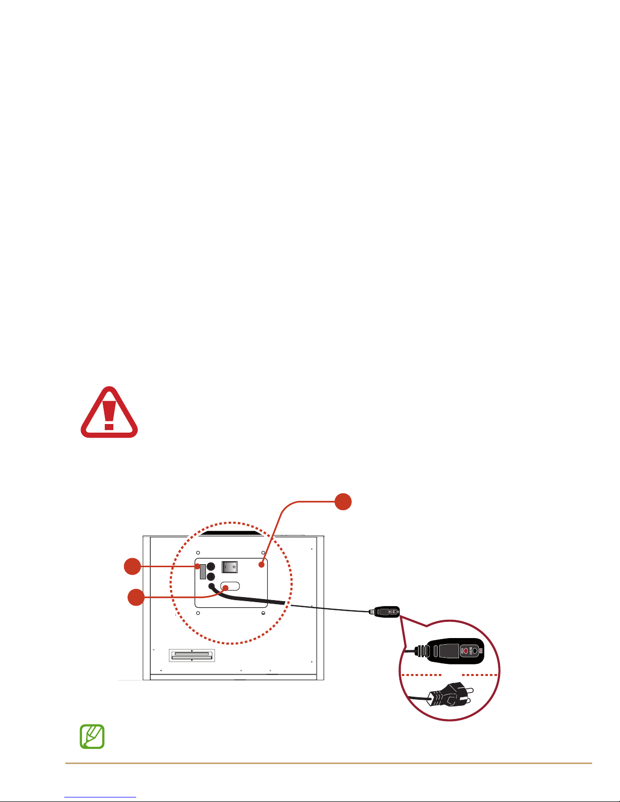
8.4 Power supply
The operating voltage of the machine is 110 Volt - 50Hz
►
chap. 5.
Before connecting the power cord to the machine make sure that the
voltage supplied meets the required specications.
Ensure that the main power line has a regular system of grounding and
all safety devices required by law.
The gure below shows the outlet where to insert the power cord and
the location of the power button.
The power button in the "O" position indicates that the machine is
turned o and the "I" indicates that the machine is on. Turn on the
machine by placing the button in position "I" only after connecting the
power cord. The fuses are located between the power button and the
power cord.
Always replace the fuse with another with the same
specifications as on the warning label; you need to
switch off and unplug the power cord, otherwise it is
impossible to replace the part.
* Socket with TEST only for USA and Canada.
29
Ofcine Gullo
26
Number Function
1
2
110V - 50 Hz
Programming port RS 232
3
USA e Canada:
F 2x3A fast
220V - 50 Hz
mod 4. Internal cylinder mod 4. external cylinder
110V - 50 Hz 220V - 50 Hz
Fuses
Electrical socket
EU: F 2X1.5A fast
USA e Canada:
F 2x3A fast
EU: F 2X1.5A fast
cod. S2041003011 cod. S2041003021 cod. S2041003010 cod. S2041003020
MODEL QUATTRO refrigerated
Number Function
1
2
110V - 50 Hz
Programming port RS 232
3
USA e Canada:
F 2x3A fast
220V - 50 Hz
mod 4. Internal cylinder mod 4. external cylinder
110V - 50 Hz 220V - 50 Hz
Fuses
Electrical socket
EU: F 2X1.5A fast
USA e Canada:
F 2x3A fast
EU: F 2X1.5A fast
cod. S2040003011 cod. S2040003021 cod. S2040003010 cod. S2040003020
MODEL QUATTRO ambient temperature
Ofcine Gullo
30

Manual of Use
27
31
Ofcine Gullo

28
1
2
8.5 Pneumatic system (for dispensers with external cylinders)
The pneumatic system provides two distinct and separate inlets:
1
Compressed air supply.
2
Nitrogen or argon gas supply.
Recall that the two pipes must be strictly separated to prevent there
being any danger of contamination of the preservation section of the
dispenser.
Set the operating pressure as indicated on the label.
Number Function
1
2
Service pressure, air (
►
chap.5)
Food-grade gas ( N2) or (Ar) (
►
chap. 5)
The dispenser leaves the factory provided with
2 extension tubes to facilitate installation in the
assembly phase.
To regulate the gasses to the recommended pressur
see chap. 5.
Ofcine Gullo
32

Manual of Use
29
8.5.1 Pneumatic system (for dispensers with internal cylinders)
Th e pneumatic system is supplied
with argon gas (E938) by means of
a cylinder provided by the factory,
inserted into the dispenser through
an opening on the topsuperiore.
Once the cartridge is inserted,
please don’t remove it for any
reasons until it is completely empty
and the display shows G EM (Gas
Empty).
If it would be necessary to remove
the cartridge in advance, please
contact the technical assistance
before proceeding with the
operation.
You can only use cylinder, issued by Wineemotion spa
because the connection and inlet are proprietary.
For installation and maintenance of the gas cylinders
see chap. 8.11.
33
Ofcine Gullo

30
8.8 Argon gas supply
The connections shown in the gure are feed points for the argon gas
supply in position
2
and compressed air in position 1.
The pressure of the food grade nitrogen or argon gas is used for the
operation of the dispensing and preservation system.
The compressed air supply is used to move the pistons to facilitate
inserting and positioning of the bottles.
Position
2
must be supplied with nitrogen or argon for food with a
degree of purity of at least 99.5%.
The supply of nitrogen or argon is facilitated through cylinders or by
the use of a nitrogen generator.
The nitrogen generator is used when you want to keep the costs of
supplying nitrogen down, especially when you have more than two
machines.
The cylinder of nitrogen or argon must have a pressure of between 150
and 200 bar, depending on the regulations of the country in which it
is used.
The cylinder must be placed in a safe, well-ventilated area and also
needs to be xed to a wall by means of chain or other fastening system.
For the use of the nitrogen generator please read your dedicated
manual from the generator manufacturer.
8.7 Refrigeration system
The R134 gas refrigeration system has a maximum working pressure
of 10 bar. The maintenance of the refrigeration system must only be
performed by a technician from an Authorized Service Center.
8.6 Climate controlled machines
This machine belongs to the N climate control class in accordance with
IEC 60335-5-24
Ofcine Gullo
34

Manual of Use
31
8.10 Warning labels
1
2
5
3
8.9 Compressed air supply
Compressed air is used to lower the pistons for the positioning and
insertion of bottles.
Compressed air is supplied to the machine by connecting the supply
line as shown in the gure above at position
2
.
For convenience compressed air may be replaced with nitrogen
pressurized at 4.5 bar.
Number Function
1
Serial of the machine, power supply voltage and the
rating of the fuses
►
chap.2
- This label indicates the model name of the machine
and species the power supply and the fuse ratings
contained in the power supply.
35
Ofcine Gullo

32
2
Caution hot surface (g.1)
- During the operation of the machine the
area indicated by the label may reach harmful
temperatures if it comes in contact with a person,
please do not touch this area for a minimum of 10
minutes after switching o the machine to allow
this surface to cool within acceptable temperature
ranges.
Attenzione temperatura elevata
Attention température élevée
Warning hot temperature
g. 1
Turn o the dispenser using the power switch to O (o) position,
unplug the power cord and turn o all electrical devices that can harm
people.
• Use all means necessary to inform the people in your surroundings
for their safety.
• If any parts are worn they should be replaced, please use only
original spare parts.
• Do not to change the characteristics of service and safety devices
and always use original spare parts.
Avoid using materials not authorized by the manufacturer.
8.11 Installation and replacement of argon
cylinders (models with internal cylinder)
3
Serial of the machine, power supply voltage and the
rating of the fuses
►
chap.2
Ofcine Gullo
36

Manual of Use
33
1. Make sure the machine is turned off.
2. Unscrew and remove the cap on top
of the dispenser which holds and protects
the cylinder from damage.
A
B
A
B
3. Attach the cap to the new cylinder
(A) and insert the cylinder into its seat. Screw
the cap counterclockwise (B) with the gas
cylinder and make sure the supply is properly
tightened and there are no leaks.
4. Tighten to close the cap on top of the
dispenser.
T he valve is reverse-threaded, rotate
counterclockwise to screw and
clockwise to unscrew.
The cylinder CANNOT BE RECHARGED!
Only cylinders issued by Wineemotion spa can be
used because the means of attachment is customized.
37
Ofcine Gullo

34
• Before carrying out any operation, make sure that the argon cylinder
is closed by the appropriate valve.
Turn off the dispenser using the power switch to O (off) position,
unplug the power cord and turn off all electrical devices that may
harm people.
• Use all means necessary to inform the people in your surroundings
for their safety.
• If any parts are worn they should be replaced, please use only
original spare parts.
• Do not to change the characteristics of service and safety devices
and always use original spare parts.
Avoid using materials not authorized by the manufacturer.
1. Replace the nitrogen cylinder when the high pressure gauge marks
10/5 bar. Below this threshold there is no guarantee for the correct
operation of the dispenser.
2. Make sure the machine is turned off.
3. Close the supply valves of the regulator (A)
A
8.11.1 Installation and replacement of argon
cylinders
(models with external cylinder)
Ofcine Gullo
38

Manual of Use
35
6. Remove the pressure regulator and replace the cylinder (D).
7. Replace the gasket to prevent any leaks.
4. Close the valve (C) of the cylinder (D).
5. Pull the valve ring (F) holding it in place so as to exhaust the residual
pressure in the regulator (D). ). Release when the pressure gauges (E1E2) show a value of 0 (zero).
A
D
C
A
D
C
E2
E1
F
I
39
Ofcine Gullo

36
N2
OR
2x3ARUL
8.11.2 Connections
1. Location of the supply lines of the gas (cylinders, generator, etc.).
2. Connect the gas lines to the gas supply and also to the pre-installed
inlets on the dispenser and pressurize the system according to the
instructions in
►
chap. 8.5.
3. Check the stability of the dispenser.
4. Connect the power supply cable to the dispenser.
Before connecting the cable to the power line socket, make sure
that the main switch is in the O (o) position and make sure the
voltage / frequency / power supplied match the values indicated on
identication label.
5. Check the working conditions of the dispenser and check that there
are no leaks (air, nitrogen / argon, etc.).
Ofcine Gullo
40

Manual of Use
37
9. Operation
PRESS
9.1 The front door
For the correct opening of the glass door, after unlocking the optional
keylock in the lower right corner, perform the following steps:
1. Press in on the glass door (g. 1).
2. Release and swing door to the desired opening (g. 2).
Avoid hygienic contamination and damage to the seals found around
the door.
9.2 Suction tube
The suction tube allows for the dispensing of wine through the tap.
The connection to the tap is extremely simple and is performed as
illustrated in g. 3, you can insert the tube as shown in step "A" in g. 3
and remove the tube as shown in step "B" in g. 3.
For proper use of the system and in accordance with hygiene rules, it
is suggested to ush the suction tube whenever you replace a bottle.
g. 1 g. 2
41
Ofcine Gullo

38
9.3 Piston components for bottle positioning
The positioning system for the wine bottle provides three main
components: the pad which serves to create a correct adhesion of the
bottle to the positioning system, the spacer which serves to compensate
for variations in height of the bottles and can be stacked together up
to a maximum of 4 and can be removed completely if necessary, and
nally the cylinder head that is xed to the pneumatic piston which is
appropriately controlled and moves up and down with a stroke of 50
mm. These parts together with the use of the spacer serve to ensure
that the neck of the bottle applies the correct pressure on the seal of
the dispenser to prevent leaks of gas (Nitrogen / Argon) and seal the
bottle for preservation.
This procedure must be performed by extracting the tube from the
machine and washing with common cleaning products designed for
food-handling equipment. Chap. Sanitation is commonly referenced
for performing normal cleaning cycles but does not cover the removal
of the suction tube, so please the recommendations in the sanitation
section together with those in this section.
g. 3
A B
Ofcine Gullo
42

Manual of Use
39
Number Function
1
2
3
bottle pad
spacer
piston head
43
Ofcine Gullo

40
9.4 Interaction and order of TAP
The order of the tap from one to four / eight and from right to left, ie
the rubunetto right is the No. 1 and one on the left is the N ° 4/8:
12345678
The keys instead go from left to right, one on the left is the N° 1 (lower
dose) and one on the right is the N° 3 (higher dose):
WP
O 17.2 C
1 2 3
Ofcine Gullo
44

Manual of Use
41
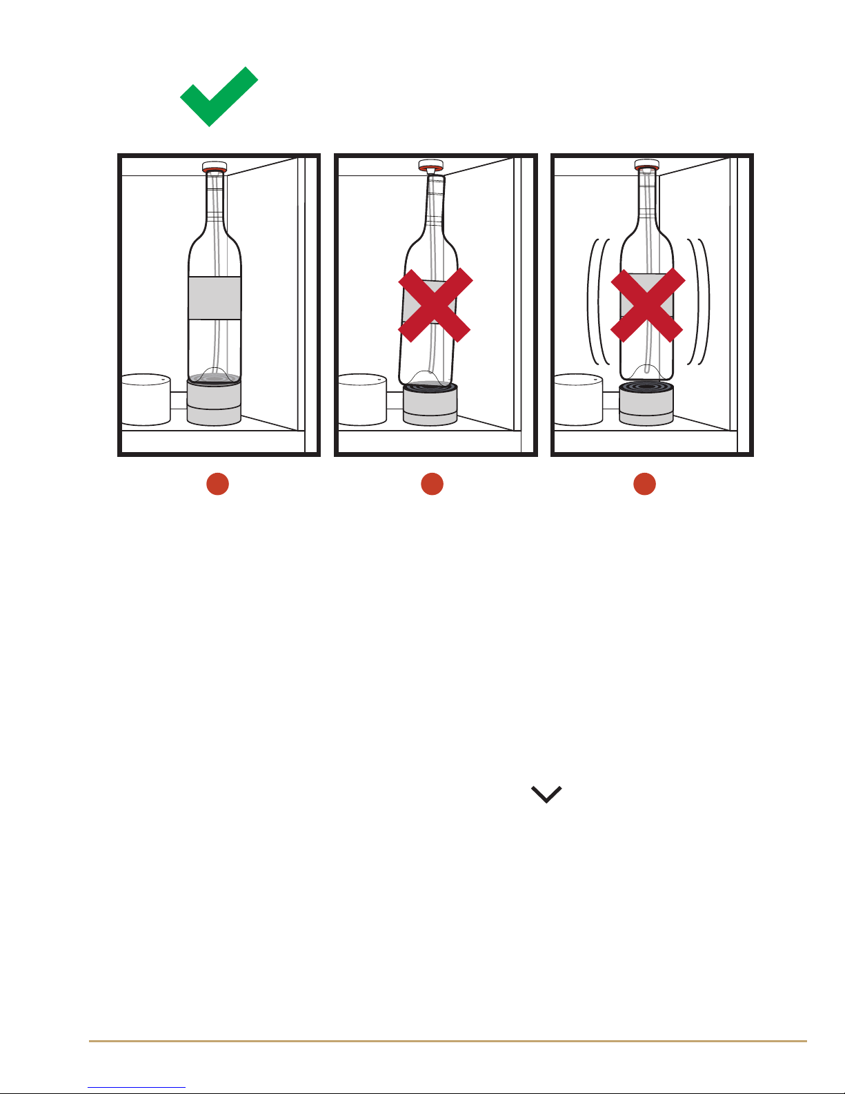
9.5 Correct positioning of the bottle
FOR DISPENSERS WITH AUTOMATIC PISTONS
For the insertion of a bottle into the machine it is suggested to perform
the following operations:
1. Make sure the machine is properly supplied either by nitrogen or
argon gas.
2. Insert suction tube
►
cHap. 9.2
WINEEMOTION
WINE
1.00$ 2.00$ 3.00$
3. Make sure the pad and the spacer of the piston are properly
positioned with consideration to the size of the bottle.
4. Press the P key in the upper left to activate the UP and DOWN
functions of the pistons (g. 1).
5. Once enabled, the LEDs of the rst 2 buttons of each tap will
illuminate indicating the following operation is possible (g. 2):
1
UP; the piston rises;
2
DOWN; the piston drops;
6. First press the function button "DOWN"
2
7. Position the bottle according to g.
A
8. Then press the function button "UP"
1
g. 1 g. 2
45
Ofcine Gullo

42
9. Verify that the bottle has sealed correctly with the gasket as
shown in g.
B
, , and note how the seal is insucient or partial in g.
C D
, which would require readjustment or addition of another spacer
and repeating the process from step "2" after removing the bottle.
10. To exit this functionality mode press the P button in the upper left
corner (g. 1).
FOR DISPENSERS WITH MANUAL PISTONS
For the insertion of a bottle into the machine it is suggested to perform
The following operations:
1. Make sure the machine is properly supplied either by nitrogen or
argon gas.
2. . Insert suction tube
►
cap. 9.2
3. Make sure the pad and the spacer of the piston are properly
positioned with consideration to the size of the bottle.
4. Position the bottle according to g.
A
5. Manually push the piston down to facilitate insertion of the bottle
into the space provided.
6. Gently release the piston and check that the neck of the bottle ts
snugly at the base of the tap seal.
A
Ofcine Gullo
46
Manual of Use
43
B C D
9.5.1 Inform the machine insertion of the bottle
in a certain position.
It serves to inform the machine that was iserita a bottle in a certain
position:
1. Press and hold the button for a few seconds at the bottom right
of the center display (Figure 1).
2. We will notice that the power of the TAP LED will begin to ash.
3. Select the nozzle where we inserted the bottle (Figure 2).
4. Once you have selected the location, the display will start a short
animation of the bottle (Figure 3).
5. Wait for the end of the animation.
47
Ofcine Gullo

44
WP
O 17.2 C
W G OK
C C 17.2 C
P
Waiting load wine
P
g. 3
g. 2
g. 1
Ofcine Gullo
48

Manual of Use
45
10. Dispensing
For a proper dispensing perform the following steps:
1. Turn on the dispenser by pressing the power button on the back.
2. At this point the machine is ready for use, simply press the button
on the desired dosage.
WP
O 17.2 C
2. Wait until the LED turns off before you remove the glass from below
the nozzle.
3. At the end of dispensing mode all LED will return to off.
49
Ofcine Gullo

46
Caution, try not to crash the glass on the regulator and
against the glass door of the bottle compartment.
Bring the glass gently to spout being careful not to damage
the glass or the door.
Warning!
The dispenser is not able to determine the level
of the wine in the bottle; in case the bottle is
removed for manual use and reinserted into
the dispenser, the preservation and correct
dispensing of the wine will be compromised.
ABSOLUTELY DO NOT REMOVE THE BOTTLE DURING USE
Ofcine Gullo
50

Manual of Use
47
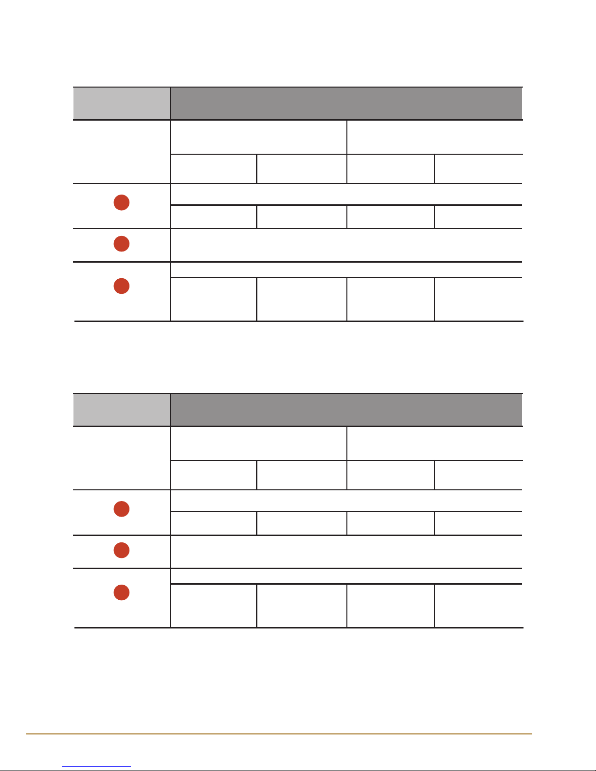
11. Display and visualization
of the system
The dispenser is equipped with a special function that can display the
various states of the refrigerating that are inside the climate controlled
dispensers.
On the screen you can view the working status of the refrigerator.
The letter that appears at the top right of the display indicates status.
In addition to the display of the refrigerator, you can monitor the status of the rest of the system.
The display will show the letters that show the various activities being
done by the system in real time:
Number Function
1
Bottle empty or absent: G EM
Full bottle inserted:
G OK
Analyzing bottle:
G AN
LEFT
RIGHT
10°C
15°C
W G OK
C C 17.2 C
10°C
LEFT
5
When the display indicates Bottle empty or absent: G EM,
the machine will not dispense and will warn with the
message on the display: NO GAS
51
Ofcine Gullo

48
4
Indicates whether the glass door of the dispenser is open or closed.
O: Open
C: Close
The dispenser responds to the glass door
being open after approximately 90 seconds
from initiation, after which the machine performs a P cycle (see function n.
1
) until the
door is reinserted/closed.
2
W: (Working) The refrigeration compressor is
running and actively cooling.
S: (Stop) The cooling system is paused between cooling cycles after reaching temperature.
D: (Defrost) Normal defrost cycles.
P: (Pausa) A 3 minute pause experienced after
changing refrigeration settings or after a defrost cycle to allow the pressure in the system
to balance and prevent immediate restarting
of the compressor.
3
View the current temperature setpoint in the
dispenser in either F° or C°. To view the realtime live temperature of the dispenser, press
and hold the
button for a few seconds.
Indicates whether the gas valve is open or
closed.
5
Ofcine Gullo
52

Manual of Use
49
WP
O 17.2 C
E1 E2 E9 E11
g. 1
Number Type of Errore
1 fan 1 locked
2 fan 2 locked
fridge emergency stop over running status
E1
E2
E9
Gas bottle almost emptyE11
The error states are coded according to the following table:
Display number one on the machine will show error screens 1 at a time,
quickly and in sequence, after which the displays are sequenced at regular intervals between error and normal states, and the error screens
will disappear once the error is xed.
11.1 Error states of the system
In figure 1 we can see an example of the display when the dispenser is
in an error state and the corresponding error codes in the table below.
The first time the error is detected, the error screen will be displayed
on the dispenser for about 1 minute.
After inserting a card the system allows configuration work to be done
normally, and if the error is not resolved then it is displayed in 1-minute
intervals for about 10 seconds at a time so as to limite the visual impact
of maulfunction of the machine to the final customer.
53
Ofcine Gullo

50
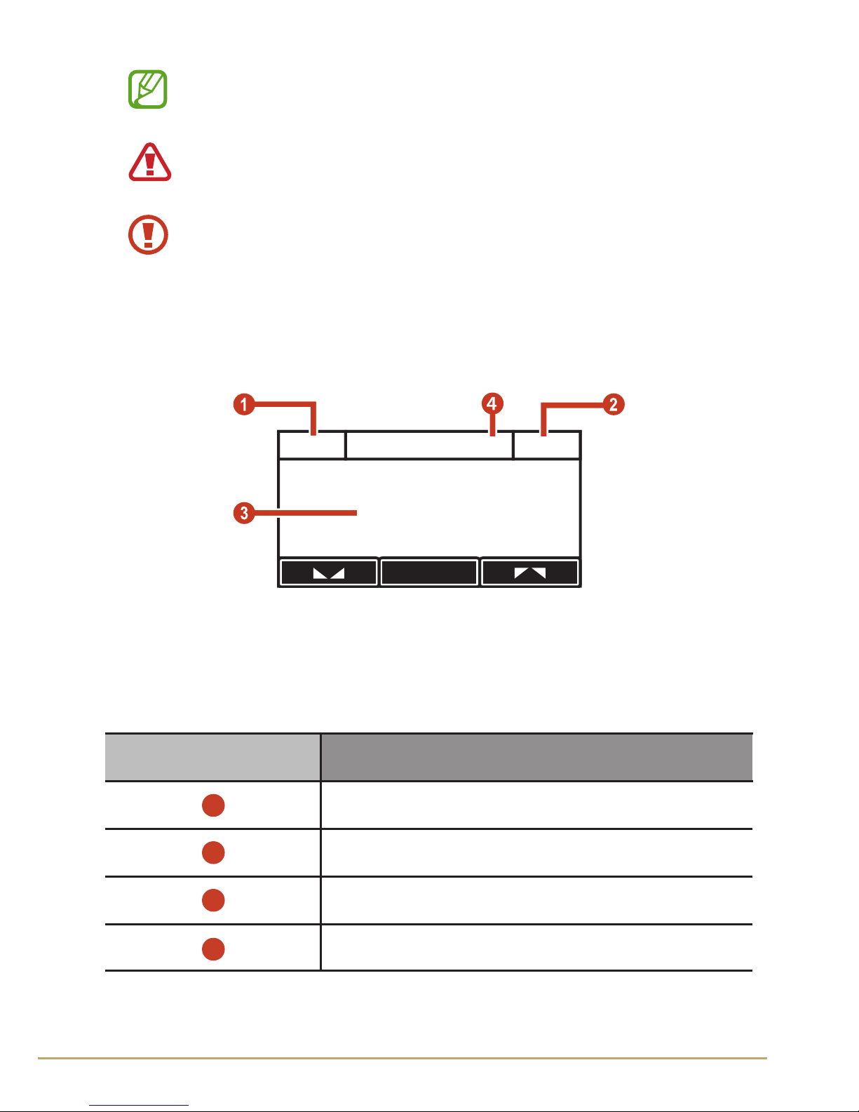
12. Description of Menus
Main Menu
It is accessed by pressing "P" button in the top left, next to the display.
Index of menu functions in the display:
13. Main menu operations
13. 1. Calibrating
13. 2. Display Setting
• Disp Backlight
• Disp Contrast
• Disp bottle led
• Exit & Save
• Exit
13. 3. Wine Setting
• Glass volume 1
• Glass volume 2
• Glass volume 3
• Bottle Volume
• Exit & Save
• Select tap & Load
• exit
13.4. Fridge Setting
• Fridge C/F
• Fridge Defrost
• Fridge Evaporate
• Fridge Temp Left
• Fridge temp Right
• Fridge Power
• Reset Default
• Exit & Save
• Exit
Ofcine Gullo
54

Manual of Use
51
Come interagire con il display:
To enter the menu you must rst press the
key to activate the arrows and which
allow scrolling through the options. Use the
key to conrm a choice or enter a menu.
To scroll through the options in this menu
press these two side buttons
(•/•) together
simultaneously.
Use the
key in the lower left to enter a
function and use the and keys to select the desired paramenter.
To exit press the two side buttons
(•/•)
together simultaneously until EXIT is shown
and then press
key at the bottom left to
EXIT the menu and return to the previous
main menu.
0927 Calibrating 750
100 Mls
EXIT
0927 Calibrating 750
100 Mls
EXIT
OK
INSTALLATION
WINE
1.00$ 2.00$ 3.00$
0927 Calibrating 750
100 Mls
EXIT
By pressing the "P" on the upper left, you
enter the technical menu of the dispenser.
55
Ofcine Gullo

52
13.1 Calibrating
This function is used to calibrate the supply of the valves, allowing the
release of the perfect amount preset from the “Wine Setting”.
Calibrating Menu
LOAD
100Mls?
SAVE
EXIT
TASTE
NO
SI
(+ / -)
tap
da 1 a 8
13. Operation from the main menu
These features can be seen on the central display.
g. 1
or 1 to 4
Ofcine Gullo
56

Manual of Use
53
Operation
Press the "P" key on the top left and enter the Main Menu, then
press
, the key to activate the scrolling with the arrow keys and
select Calibrating
Once this function is selected, the center LED of each nozzle lights to
allow selecting which tap to work on (fig. 1).
Action Function
LOAD
It is used to load the liquid initially for
dispensing.
TASTE
It is used to dispense a calibration supply
which must be equal to 100ml. You must
use a graduated cylinder of measuring
cup accurately degraded in ml.
SAVE It is used to save the calibration parameters.
Exit Exit from the menu without saving.
To perform a Calibrating procedure use a bottle filled with
750 ml of water.
100Mls ?
If the supplied amount is equal to 100ml
confirm with the
key, If it is not, use
the and keys to enter the actual
amount dispensed as measured using your
desired measuring device and confirm by
pressing the
key .
Bevore performing the Calibrating make sure to insert the
bottle using the appropriate procedure
►
cap. 9.4
57
Ofcine Gullo
54
0927 Calibrating (2) 750
100 Mls ?
OK
-
+
Number Function
1
2
3
Once finished calibrating is important to SAVE, otherwise
the system will return to the previous parameters.
Dusing the LOAD and TASTE operations keep a measuring
cylinder under the nozzle because these transactions
involve the dispensing of fluid.
Base time for delivery of 100 Mls.
Residual volume left in the bottle.
The amount dispensed from the tap.
The TASTE operation must be repeated until the dispenser
supplies the exact quantity required (100 mls).
g. 2
4
Tap number currently being calibrated
Ofcine Gullo
58

Manual of Use
55
Operation
Press the "P" key on the top left and enter the Main Menu, press the
, key to activate the scrolling with the arrow keys and select Display
Setting.
Display Setting
Disp. Backlight
Disp. Contrast
Disp. Bottle Led
Exit & Save
Select tap
13.2 Display Setting
This function is used to set the functional parameters of the display
and lighting of the bottle compartment.
59
Ofcine Gullo

56
Option Function
Disp. Backlight
It is used to set the display backlighting
brightness.
Disp. Contrast
Used to set the contrast of the display.
Disp bottle led
Used to set the brightness of the bottle
lighting.
Exit & Save
Used to exit the menu and save the new
parameters.
Exit Exit the menu without saving
13.3 Wine Setting
This function is to set the portions of the inserted wine.
Wine Setting
Glass volume 2 Glass volume 3Glass volume 1
Select tap
tap
da 1 a 8
g. 1
Ofcine Gullo
60

Manual of Use
57
Wine Setting
Glass volume 2 Glass volume 3Glass volume 1
Select tap
tap
da 1 a 8
Bottle Volume
Exit & Save
1
Indicates the tap being modified.
Glass Volume 1
Used to set the volume of product
dispensed from button "1".
Glass Volume 2
Used to set the volume of product
dispensed from button “2”.
Glass Volume 3
Used to set the volume of product
dispensed from button “3”.
0927 tap 2 750
10 gr
EXIT
2
3
4
Operation
Press the "P" key on the top left and enter the Main Menu, press
the
, key to activate the scrolling with the arrow keys and select
Calibrating. Choose which tap to work with using the Select Tap &
Load function.
Option Function
61
Ofcine Gullo

58
Bottle Volume
Used to set the volume capacity of the
bottle (default 750 ml).
Exit & Save
Used to exit the menu and save the new
parameters.
Select Tap & Load
Used to select the dispensing tap on which
to perform the changes
Exit Exit the menu without saving
15.4 Fridge Setting
This function is used to set the parameters of the refrigeration system.
Operation
Press the "P" key on the top left and enter the Main Menu, press the
, key to activate the scrolling with the arrow keys and select Fridge
setting
The minimum portion is 10gr, below this threshold the
dispensiong option is set to o.
OPEN
When the option is set to OPEN, pressing
that button will dispense continuously
until the button is released
OFF
When the option is set to OFF, pressing
that button will not dispense any volume.
With the OPEN option, the portion is adjusted by the time
the button is depressed.
Ofcine Gullo
62

Manual of Use
59
Option Function
Fridge C/F
Used to set the temperature unit scale for
Celsius ( C° ) or Fahrenheit ( F° ).
Fridge Defrost
Used to set the defrost cycle frequency:
1 – light defrost ( 2 times per day)
2 – medium defrost ( 3 times per day)
3 – heavy defrost ( 5 times per day)
Fridge Evaporate
Used to set the evaporation time.
1 – low evaporation
2 – medium evaporation
3 – high evaporation
Fridge Temp. Left
(5/25 C°) Used to set the temperature of
the left compartment.
Fridge Temp. Right
Function not available
Reset Default
Used to reset the parameters to the default
state.
Exit & Save
Used to exit the menu and save the new
parameters
Exit
Exit the menu without saving
63
Ofcine Gullo

60
If the Fridge Temp. Left falls below the minimum
temperature that the machine can reach, the refrigeration
automatically turns off, displaying its status as OFF.
After making any changes remember to press Exit & Save
to send the new parameters to the refrigeration system.
After sending the new parameters, the compressor will
turn off and restart after 3 minutes. This is to allow for the
refrigerant to re-stabilize the pressure for a safe restarting
of the compressor.
Ofcine Gullo
64

Manual of Use
61
14. Maintenance and cleaning
14.1 Minimum qualication of personnel
Daily, periodic, extraordinary, and sanitatioin maintenance can be
performed by any unskilled operator.
Repairs must be performed by a qualied technician provided by an
authorized Wineemotion service center.
14.2 Daily maintenance
Clean the machine from the residues of wine with a soft sponge
and neutral detergents that do not aect either the stainless steel
or polycarbonate panels (front panel bottle display and front ditital
display).
Remove the grille as shown in the gure and remove the drip trays
underneath. Wash the trays and clean the interior cabinet of the
machine
Clean the wine suction tubes by immersing it in a container of water.
Thoroughly clean the dispensers to preserver the
quality of the wine.
65
Ofcine Gullo

62
14.3 Periodic manintenace
Clean the spouts and suction tubes of every bottle position for every
10 bottles consumed and no later than 20 days of operation, coinciding
with the wine bottle running out in that position. Perform the cleaning
with suitable detergents for food-grade equipment and wine, usually
citric acid.
It is a good idea to perform a cleaning before inserting a new bottle.
The cleaning is done in the following way:
→ a. Remove the bottle of wine and insert a bottle with 750ml capacity
containing a solution of water and 1 teaspoon or 20cc of cleaning
product provided by the supplier (
►
chap.19.1- SaniPack MP 100 in
packets o SaniKleen 512 i512 in containers of 500ml), with a ration of
20cc per 750ml of water.
→ b. Dispense the solution through the tap, waiting 10 to 15 seconds
between each pour and repeat until the solution is exhausted
→ c. Replace the bottle of cleaning solution with a 750ml bottle of
drinking water
→ d. Dispense the entire bottle of drinking water.
→ e. Replace the bottle of water with a bottle of wine and dispense
once to expel the last bit of water left in the suction tube.
Ofcine Gullo
66

Manual of Use
63
14.4 Extraordinary maintenance
Extraordinary cleaning should be done every 6 months for a perfectly
sanitized dispenser, using a disinfectant cleaner specic for enological
use and in the doses provided by the manufacturer. An optimal time
for such cleaning is during the changing of the bottles.
The procedure is as follows:
→ a. Replace the bottle of wine with a 750ml bottle containing a
solution of water and detergent to the extent provided by the supplier
(
►
chap.19.2- SaniKleen 512 ).
→ b. Dispense the solution through the tap, waiting 10 to 15 seconds
between each pour and repeat until the solution is exhausted.
→ c. Remove the bottle of wine and insert a bottle with 750ml capacity
containing a solution of water and 30cc of cleaning product provided
by the supplier (► chap.21.2- SaniKleen 512 ),with a ration of 30cc per
750ml of water.
→ d. Dispense the entire bottle of cleaning solution.
→ e. Replace the bottle of cleaning solution with a 750ml bottle of
drinking water
→ f. Dispense the entire bottle of drinking water.
→ g. Replace the bottle of water with a bottle of wine and dispense
once to expel the last bit of water left in the suction tube.
PERFORM AN INTENSE CLEANING BEFORE LEAVING
THE DISPENSER NOT OPERATING FOR A PERIOD OF
MORE THAN 3 DAYS.
PLEASE NOTE THAT THE USE OF SWEET OR
PARTICULARLY AGED WINES MAY CAUSE THE
FORMATION OF DEPOSITS IN VARIOUS DUCTS,
INTENSIFY THE CLEANING IN THIS CASE.
67
Ofcine Gullo

64
14.5 Troubleshooting notes
Problem Reason Solution
The machine does not turn on. The power button is off.
The power cord is not
connected.
Switch on the power button.
Connect the power cord.
Nitrogen is leaking. Gas cylinder connections are
loose.
Tighten connections.
The bottle is too short. Enter the shim between the
piston and metallic bottle
pusher cup.
The bottle is not correctly
inserted.
Check that the bottle
compresses correctly against
the seal pad of the dispenser.
Check the dispenser for leaks.
The wine dispensing is not
continuous
The gas cylinder is empty.
The pressure is low.
Replace the gas cylinder
Check the pressure.
The suction tube is not fitted
correctly
Insert the suction tube
correctly.
The suction tube filter is
blocked.
Remove the bottle and clean
the filter.
The machine is unable to reach
the correct temperature
There is insufficient air
circulation.
The fans are switched off.
The refrigeration system is not
working.
Check the machine has been
installed correctly, with the
required air circulation gaps.
Call technical support.
Call technical support.
Wine is dripping from the steel
tube of the dispenser
Wine sediments in the
dispenser.
Perform cleaning maintenance
with citric acid solution, as
described in the manual
Ofcine Gullo
68

Manual of Use
65
14.6 PPE required for maintenance personnel
All technicians performing repairs must wear protective equipment
for individuals, as dened under the Health & Safety At Work laws. In
particular, protective gloves and eye-wear are required.
14.7 Precautions for maintenance
These instructions are not intended for people including
children, with reduced physical or mental capacity, or
without the necessary experience and training, without
supervision or instruction by a person responsible for their
safety. Children must be supervised to ensure that they do not play
with the device.
69
Ofcine Gullo

66
When disposing of the machine, it is necessary to separate the plastic
and electrical components, which must be sent to separate waste sites
in accordance with local regulations.
Ordinary recycling can be used for the main metal body of the machine
as it is composed of steel, copper and aluminium.
Manufacturer:
WINEEMOTION S.P.A.
con sede legale in Strada di Sant'Appiano, 9/a
FOR
declares under sole responsibility that the product
DISPENSER AUTOMATIC FOR WINE model:
QUATTRO (WND040)
to which this declaration relates is in conformity with the
following standards:
15. Disposal of the machine
16. Declaration of compliance
Headquarters and factory
Via Della Torricella 29, Antella, Bagno a Ripoli
50012 Florence - Italy
Tel. +39 055 65 60 3324
+39 055 62 18 07
ofcinegullo.com | info@ofcinegullo.com
Ofcine Gullo
70

Manual of Use
67
-CEI EN 61000-3-2
“Electromagnetic Compatibility ” EMC. Part
3: limits. Section 2: limitations of voltage
fluctuations and flicker in low voltage supply
systems ( appliances with rated current <16A
per phase). File 4749 C
-CEI EN 61000-3-3 “Electro-Magnetic Compatibility” EMC
.Part3: limits. Section 3 limiting in voltage
fluctuation and of flickers in low voltage
feeding systems for appliances with nominal
current <16A . File 2650E
CEI EN 60335-1 modification A2, A13,
A14, A15, A16
“Household and similar electrical appliances
and similar”. General norm file n. 4196C
-CEI EN 50081-1 “Electro-Magnetic Compatibility” general
emissions standards Part 1:residential,
commercial and light industry environments.
File 3215 June 1997
-CEI EN 50082-1 “Electro-Magnetic Compatibility” general
immunity standards. Part 1: residential,
commercial and light industry environments.
File 4498 May 1998
Also declares that it conforms with the requisite Directives:
-Low Voltage Directive 2006/95 CE ( Directive: regulation concerning
the approach of State Members’ laws regarding the electric material
destined to be used within certain voltage limits)
- Electro-Magnetic Compatibility 2004/108 CE. (Directive regarding the
approach of State Members’ laws concerning about electro-magnetic
compatibility.
71
Ofcine Gullo

68
WE WARRANT that the Wineemotion Wine Serving Systems (the
Goods), models OTTO and QUATTRO, manufactured by Wineemotion
S.p:A. are sold and delivered to the Purchaser free from manufacturing
defects in materials and workmanship.
From the Installation Acceptance date Wineemotion (the Company)
undertakes that the Warranty shall cover free of charge to the Purchaser:
• the repair or replacement (at the Company’s sole discretion) of any
functionally inoperative PARTS that according to the Company’s
incontestable judgement, are deemed to be defective in workmanship
or materials because of a manufacturing defect detected within the
rst 24 months (excluding software);
• the diagnosis and elimination of any errors found in the SOFTWARE
programmes (provided that the errors are recurrent and documented)
by way of supply of new corrected versions of the software for the rst
6 months;
• the warranty shall include only the replacement of those defective
17. Garanzia della macchina
Also declares that it is formally conformed to all the Directives of the
MACHINES REGULATION CE 98/37as, following the comma 2 enclosed
1, the risk of the machine is to be considered MAINLY electric, therefore
is enough to full the above regulations 2006/95 CE// 2004/108 ce
Wineemotion S.p.A.
Strada di Sant'Appiano, 9/a
50021 Barberino Val D'Elsa
Firenze Italy
P.I. 06231920486
13_______________________
the last 2 digit of the year of production
Ofcine Gullo
72

Manual of Use
69
parts and shall not include LABOUR .
This is the Company’s entire liability in respect of such Warranty.
Wineemotion shall provide warranty services directly or through its
own authorised repair centres. Materials covered by warranty must
be sent to the Repair Centres free of charge for the manufacturer and
shall be sent back at the customer’s expense. Any parts replaced shall
remain the property of Wineemotion.
The Purchaser must save proof of the Installation Acceptance date as
detailed on the Installation Acceptance Certicate together with the
sales receipt or invoice stating the item numbers of the purchased
Goods. All claims for Goods under Warranty shall be forwarded to the
Company together with proof of the Installation Acceptance date and
a copy of this Statement of Warranty.
In the event that installation of the Goods is delayed by the Purchaser
for more than 1 month from the original date of delivery of the Goods
as requested by the Purchaser, then the Installation Acceptance date
shall be deemed to commence 1 month after the original date of
delivery of the Goods was requested. The Warranty only applies to the
original Purchaser of the Goods and is not transferable.
All Warranty service will be provided by the Company during normal
working hours.
Replaced parts become the property of the Company and repairs or
replacements do not extend the Warranty period. Any transportation
costs (including return shipment) associated with a Warranty claim will
be the responsibility of the Purchaser.
THE WARRANTY DOES NOT COVER any defect, failure or damage
arising from:
a) failure to follow normal operating procedures and instructions or
failure to ensure proper care, use and regular maintenance as outlined
in the documentation provided by the Company;
b) incorrect transportation, installation, removal or handling;
c) the eects of fair wear and tear, rusting or damage to varnish, enamel
or paintwork;
d) periodic general cleaning and any labour or part charges incurred as
a result of service in the nature of maintenance and support including
the replacement of consumable parts, house fuses or resetting of
73
Ofcine Gullo

70
circuit breakers;
e) incorrect storage or exposure to unusual or excessive environmental,
chemical, atmospheric, mechanical, electrical (including defective
house wiring or by operating the Goods on incorrect voltage or cycles
or uctuations or interruptions in the power supply) or thermal stress
during the course of installation or use;
f) any drawing, design or specication supplied by the Purchaser;
g) wilful or accidental damage, misuse, abuse or negligence;
h) any modication (whether by alteration, deletion, addition, repair or
otherwise) to the Goods by the Purchaser or any other unauthorised
persons unless the Purchaser has obtained the prior written consent
of the Company. If any such unauthorised modication is made, then,
without prejudice to the Company’s other rights and remedies, the
Warranty will be null and void;
i) the use of any spare parts that are not originals as supplied by the
Company;
j) if the original identication markings on the Goods have been
removed, defaced, or altered.
The Company will be under no liability under the above Warranty (or
any other warranty, condition or guarantee):
a) if the total price for the Goods has not been paid by the Purchaser
by the due date for payment;
b) for any indirect, incidental or consequential loss, damage, cost or
expense of any kind whatsoever, whether arising under an accident,
contracts tort (including negligence) or otherwise;
c) for compensation for any reasons whatsoever resulting from any
inoperative down time of the Goods including any loss of wine or
other beverage.
d) If the labels or marks are removed from the machines.
If a defect or failure of the Goods is found upon investigation not to be
the Company’s responsibility under this Warranty, the Company may
charge the Purchaser for all reasonable costs and expenses incurred by
the Company in the course of, or in consequence of, such investigation.
Without prejudice to the foregoing, the Company reserves the right to
charge for travelling time and incidental expenses incurred in respect
of attendance at your premises to investigate and rectify any problem
Ofcine Gullo
74

Manual of Use
71
18. Certications held by
SERIES 2 Dispensers
International:
CB
reported by you.
The Company’s obligations under the Warranty are contingent upon
the Company’s agents or servants being given full details of the defects
without delay and adequate time and access to the Goods during
normal working hours to rectify such defect. If the Company recties
the defect within a reasonable period of time then the Company will
have no other liability in any respect of, or arising from, such defect.
The above Warranty does not extend to parts, materials or equipment
not manufactured by Wineemotion S.p.A. in respect of which the
Purchaser will only be entitled to the benet of any such warranty
or guarantee as is given bythe supplier or service provider to the
Company.
WINEEMOTION S.p.A.
Amministratore Delegato
Riccardo Gosi
75
Ofcine Gullo

72
SaniPack MP 100 Solution sanitizing powder
Description
Water-soluble compound powder capable of generating a solution
of chlorine dioxide, formulated specically for the basic sanitization
of automated systems in dispensers of drinks intended for human
consumption. When used in accordance with the instructions, quickly
eliminates odours, biolms, microorganisms and fungi without
altering the avour of the drink. Although the product, in normal
concentrations, does not corrode metals, plastics, or rubber, it should
not be used for cleaning the exterior of the machine.
Appearance
Hermetically sealed silver sachet with easy opening.
Handling
Keep in the original container; open the bag immediately before
use; avoid exposure to heat; do not eat, drink or smoke during the
preparation of the solution.
Storage
Keep out of the reach of children, in a cool place, away from water,
moisture, ame or sparks.
Disposal of used product
Dilute the used product with water before discharge into the sewer
system.
19. Authorised cleaning
products
Sanipak™ MP 100
Ofcine Gullo
76

Manual of Use
73
Warnings-Tips
For the preparation of the sanitising solution, use a dedicated container
to which an appropriate label has been applied. When nished, rinse
with running water, stop and store for the next cleaning operation. Do
not leave used solution in the container: remove the solution at the
end of each cleaning operation.
Do not use the container for other purposes.
Procedure for the creation of a solution containing a concentration of
130 ppm of active ingredient
- Fill the bottle with 750 cc. drinking water
- Empty the contents of the sachet into the water
- Stir until the powder is completely dissolved
- Circulate the solution through the system to be cleaned
- If possible, ensure the solution remains in contact with the surfaces to
be treated for at least 30 seconds
- Rinsed as per your required procedures.
SANITATION SOLUTION
Desinfektionslösung
Soluzione Sanificante
Solution Désinfectante
Solución Desinfectante
Carefully read the user manual for the
correct preparation of the sanctifying.
chapter 20
Lesen Sie die Bedienungsanleitung für die
richtige Vorbereitung der Heiligung. Kapitel
20
Leggere attentamente il manuale d'uso per
la corretta preparazione della soluzione
santicante. capitolo 20
Lire attentivement le manuel d'utilisation
pour la préparation correcte de la sanctication. Chapitre 20
Lea atentamente el manual de usuario para
la correcta preparación de la santicación.
Capítulo 20
Do not use the product for other uses.
cap. 20
EN
D
I
F
ES
77
Ofcine Gullo

74
03/10/2010
% in peso Classific. CAS # EINECS
100 R29
3.2
3.3
3.4
3.5
3.6
3.7
3.8
miscela esclusiva di sali minerali considerata come segreto
commerciale
Occhi
Nocivo se ingerito. Può causare irritazioni alla bocca, alla gola, allo stomaco. Può
causare dolori, nausea, vomito e diarrea. Può causare debolezza ed affaticamento
Inalazione
Dannoso se inalato, l'aspirazione di polveri generate dal prodotto possono causare
irritazioni all'apparato respiratorio. Possono ustionare le membrane delle mucose, creare
broncospasmi, tosse,con un successivo edema polmonare. Può causare tosse, difficoltà
respiratoria, e bruciore alla gola
3.1
Centro Antiveleni: Pavia 0382/24444; Milano 02/66101029; Bergamo 800883300; Firenze
055/7947819; Roma Gemelli 06/3054343; Roma Umberto I 06/49978000; Napoli
081/7472870
Prodotto importato/distribuito da
Numeri telefonici di chiamata
urgente
Kronotek Srl - Via Bachelet, 38 30037 Gardigiano di Scorze' (VE)
Tel. 041.5830053 - Fax 041.448758 - E-mail info@kronotek.it
Nome commerciale
Tipo di prodotto
Uso
Data revisione
1. Identificazione del prodotto
Sanipak™ MP 100
Polvere effervescente, auto-attivante per la generazione di Biossido di Cloro
Preparazione di soluzioni sanificanti
Sostanze ritenute pericolose ai sensi della direttiva 67/548/CEE e relativa classificazione
Sostanza
Note: i valori percentuali non vengono dichiarati in quanto rappresentano approssimativamente i valori di formulazione
2. Composizione/informazione sugli ingredienti
Irritante per gli occhi,per l'apparato respiratorio e per la pelle
Nocivo se ingerito. Può causare dolori, nausea, vomito e diarrea. A seguito
dell'esposizione all'acqua o all'umidità il prodotto rilascia Biossido di Cloro
Una prolungata o ripetuta esposizione alle polveri può causare problemi polmonari
Altri rischi
A seguito di esposizione all'umidità ed all'acqua, il prodott
o rilascia Biossido di Cloro gas.
L'inalazione del Biossido di Cloro gas, può causare irritazione, tosse, dispnea, e bruciori
alle membrane delle mucose. L'inspirazione di quantità significative di gas può
comportare rischi di edema e bronchiti
Pelle
Principali pericoli
Carcinogenicità NPT - No IARC - No OSHA - No ACGIH - No
Prodotto dannoso per la pelle, irritante in caso di sovraesposizioni. Il contatto della
polvere con la pelle umida può causare bruciore. Il contatto prolungato può provoca
re
dermatiti. Il contatto con una soluzione contenente 100 ppm di Biossido di Cloro è
risultata leggermente irritante sulla pelle del coniglio
3. Identificazione dei pericoli
Vedere anche la sezione 11
Patologie che aggravano i
sintomi
Prodotto irritante, causa severe irritazioni, bruciore e danneggia gli occhi
Ingestione
Material Safety Data Sheet
4.1
4.2
4.3
4.4
5.1
5.2
5.3
5.4
5.5
5.6
5.7
6.1
6.2
6.3
Precauzioni individuali speciali
Pericoli speciali derivanti dalla sostanza
o dalla miscela
Raccomandazioni per gli addetti
all'estinzione degli incendi
Contatto con la pelle
Contatto con gli occhi
Punto di infiammabilità
Metodi di pulizia
4. Misure di pronto soccorso
Inalazione
Rischi da combustione Evitare di respirare i fumi
6. Misure in caso di fuoriuscita accidentale
Precauzioni ambientali Contenere le perdite con terra, sabbia od adeguato mezzo assorbente
5. Misure antincendio
Estintori raccomandati
Estintori vietati
Mezzi di protezione
Ingestione
Recuperare se possibile. I residui del prodotto sono da considerare come rifiuti speciali pericolosi. La pericolosità dei
Product datasheet
Ofcine Gullo
78

4.1
4.2
4.3
4.4
5.1
5.2
5.3
5.4
5.5
5.6
5.7
6.1
6.2
6.3
Precauzioni individuali speciali
Pericoli speciali derivanti dalla sostanza
o dalla miscela
Il contatto con l'acqua della polvere genera Biossido di Cloro gas. Il LEL
(Lower Explosive Limit) per il Biossido di Cloro è il 10%. Qualora grandi
quantità di prodotto siano coinvolte nell'incendio, l'uso di acqua
nebulizzata in ambienti confinanti può determinare l'emissione di una
quantità di gas tale da determinare il rischio di esplosione. L'utilizzo di
grandi quantità d'acqua determina
la diluizione e l'eliminazione del
rischio
Non applicabile
Raccomandazioni per gli addetti
all'estinzione degli incendi
In caso di incendio raffreddare immediatamente i contenitori per evitare il
pericolo di esplosioni e lo sviluppo di sostanze potenzialmente pericolose
per la salute
Innondare con acqua
Contatto con la pelle
Contatto con gli occhi
Lavare immediatamente con abbondante acqua anche sotto le palpebre per almeno 15
minuti. Consultare subito un medico
Punto di infiammabilità
Metodi di pulizia
4. Misure di pronto soccorso
Inalazione
Elmetto prot
ettivo con visiera, indumenti ignifughi (giacca e pantaloni
ignifughi con fasce intorno a braccia, gambe e vita), guanti da intervento
(antincendio, antitaglio e dielettrici), autorespiratore (autoprotettore)
Una soluzione contenente 100-200 ppm di biossido di cloro non
necessita di neutralizzazione
Rischi da combustione Evitare di respirare i fumi
Impedire che penetri nella rete fognaria se non previa abbondante
diluizione con acqua
6. Misure in caso di fuoriuscita accidentale
Precauzioni ambientali Contenere le perdite con terra, sabbia od adeguato mezzo assorbente
Raccogliere il prodotto per lo smaltimento. Se in soluzione acquosa,
assorbirlo con materiale inerte
Successivamente alla raccolta, lavare con abbondante acqua la zona ed
i materiali interessati
5. Misure antincendio
Nessuno
Estintori raccomandati
Estintori vietati
Mezzi di protezione
Raccogliere velocemente il prodotto indossando maschera ed indumento
protettivo
Indossare maschera, guanti ed indumenti protettivi
Consultare immediatamente un medico. NON INDURRE IL VOMITO, con il vomito il
prodotto può entrare accidentalmente nei polm
oni e provocare broncopolmonite o edema
polmonare. In caso di vomito spontaneo, tenere la testa al di sotto del bacino per
prevenire l'aspirazione dei liquidi espulsi. Se cosciente ed in grado di ingerire,
somministrare molta acqua
Ingestione
Aerare l'ambiente. Rimuovere subito il paziente dall'ambiente contaminato e tenerlo a
riposo in ambiente ben aerato. In caso di malessere consultare un medico
Lavare abbondantemente con acquaesapone le parti entrate in contatto con la
soluzione; eliminare gli abiti contaminati
. Se l'irritazione persiste, contattare un medico
7.1
7.2
7.3
7.4
8.1
8.2
8.3
8.4
10.1
10.2
10.3
10.4
Pressione di vapore
Punto di ebollizione
Stabilità
Reazioni pericolose
pH sol. Acquosa 0.01%
cca id otnuP
Prodotti pericolosi di decomposizione
10. Stabilità e reattività
Sostanze incompatibili
9. Proprietà Fisiche e Chimiche
Indicazione per i locali Freschi e ben aerati
Materiali e rivestimenti idonei
Precauzioni di manipolazione
Protezione delle mani
7. Manipolazione e stoccaggio
Condizioni di stoccaggio
Protezione degli occhi
Colore
8. Controllo dell'esposizione individuale
Odore
Aspetto
Protezione respiratoria
Protezione della pelle Indossare indumenti
Recuperare se possibile. I residui del prodotto sono da considerare come rifiuti speciali pericolosi. La pericolosità dei
Manual of Use
75
4.1
4.2
4.3
4.4
5.1
5.2
5.3
5.4
5.5
5.6
5.7
6.1
6.2
Precauzioni individuali speciali
Pericoli speciali derivanti dalla sostanza
o dalla miscela
Il contatto con l'acqua della polvere genera Biossido di Cloro gas. Il LEL
(Lower Explosive Limit) per il Biossido di Cloro è il 10%. Qualora grandi
quantità di prodotto siano coinvolte nell'incendio, l'uso di acqua
nebulizzata in ambienti confinanti può determinare l'emissione di una
quantità di gas tale da determinare il rischio di esplosione. L'utilizzo di
grandi quantità d'acqua determina
la diluizione e
l'eliminazione del
rischio
Non applicabile
Raccomandazioni per gli addetti
all'estinzione degli incendi
In caso di incendio raffreddare immediatamente i contenitori per evitare il
pericolo di esplosioni e lo sviluppo di sostanze potenzialmente pericolose
per la salute
Innondare con acqua
Contatto con la pelle
Contatto con gli occhi
Lavare immediatamente con abbondante acqua anche sotto le palpebre per almeno 15
minuti. Consultare subito un medico
Punto di infiammabilità
4. Misure di pronto soccorso
Inalazione
Elmetto protettivo con visiera, indumenti ignifughi (giacca e pantaloni
ignifughi con fasce intorno a braccia, gambe e vita), guanti da intervento
(antincendio, antitaglio e dielettrici), autorespiratore (autoprotettore)
Rischi da combustione Evitare di respirare i fumi
6. Misure in caso di fuoriuscita accidentale
Precauzioni ambientali Contenere le perdite con terra, sabbia od adeguato mezzo assorbente
5. Misure antincendio
Nessuno
Estintori raccomandati
Estintori vietati
Mezzi di protezione
Indossare maschera, guanti ed indumenti protettivi
Consultare immediatamente un medico. NON INDURRE IL VOMITO, con il vomito il
prodotto può entrare accidentalmente nei polmoni e provocare broncopolmonite o edema
polmonare. In caso di vomito spontaneo, tenere la testa al di sotto del bacino per
prevenire l'aspirazione dei liquidi espulsi. Se cosciente ed in grado di ingerire,
somministrare molta acqua
Ingestione
Aerare l'ambiente. Rimuovere subito il paziente dall'ambiente contaminato e tenerlo a
riposo in ambien
te ben aerato. In caso di malessere consultare un medico
Lavare abbondantemente con acquaesapone le parti entrate in contatto con la
soluzione; eliminare gli abiti contaminati
. Se l'irritazione persiste, contattare un medico
7.1
7.2
7.3
7.4
8.1
8.2
8.3
8.4
Pressione di vapore
Punto di ebollizione
pH sol. Acquosa 0.01%
cqua
10. Stabilità e reattività
9. Proprietà Fisiche e Chimiche
Indicazione per i locali Freschi e ben aerati
Materiali e rivestimenti idonei
Precauzioni di manipolazione
Protezione delle mani
7. Manipolazione e stoccaggio
Condizioni di stoccaggio
Protezione degli occhi
Colore
8. Controllo dell'esposizione individuale
Odore
Aspetto
Protezione respiratoria
Protezione della pelle Indossare indumenti
Recuperare se possibile. I residui del prodotto sono da considerare come rifiuti speciali pericolosi. La pericolosità dei
79
Ofcine Gullo

76
4.1
4.2
4.3
4.4
5.1
5.2
5.3
5.4
5.5
5.6
5.7
6.1
6.2
6.3
Precauzioni individuali speciali
Pericoli speciali derivanti dalla sostanza
o dalla miscela
Il contatto con l'acqua della polvere genera Biossido di Cloro gas. Il LEL
(Lower Explosive Limit) per il Biossido di Cloro è il 10%. Qualora grandi
quantità di prodotto siano coinvolte nell'incendio, l'uso di acqua
nebulizzata in ambienti confinanti può determinare l'emissione di una
quantità di gas tale da determinare il rischio di esplosione. L'utilizzo di
grandi quantità d'acqua determina
la diluizione e
l'eliminazione del
rischio
Non applicabile
Raccomandazioni per gli addetti
all'estinzione degli incendi
In caso di incendio raffreddare immediatamente i contenitori per evitare il
pericolo di esplosioni e lo sviluppo di sostanze potenzialmente pericolose
per la salute
Innondare con acqua
Contatto con la pelle
Contatto con gli occhi
Lavare immediatamente con abbondante acqua anche sotto le palpebre per almeno 15
minuti. Consultare subito un medico
Punto di infiammabilità
Metodi di pulizia
4. Misure di pronto soccorso
Inalazione
Elmetto protettivo con visiera, indumenti ignifughi (giacca e pantaloni
ignifughi con fasce intorno a braccia, gambe e vita), guanti da intervento
(antincendio, antitaglio e dielettrici), autorespiratore (autoprotettore)
Una soluzione contenente 100-200 ppm di biossido di cloro non
necessita di neutralizzazione
Rischi da combustione Evitare di respirare i fumi
Impedire che penetri nella rete fognaria se non previa abbondante
diluizione con acqua
6. Misure in caso di fuoriuscita accidentale
Precauzioni ambientali Contenere le perdite con terra, sabbia od adeguato mezzo assorbente
Raccogliere il prodotto per lo smaltimento. Se in soluzione acquosa,
assorbirlo con materiale inerte
Successivamente alla raccolta, lavare con abbondante acqua la zona ed
i materiali interessati
5. Misure antincendio
Nessuno
Estintori raccomandati
Estintori vietati
Mezzi di protezione
Raccogliere velocemente il prodotto indossando maschera ed indumento
protettivo
Indossare maschera, guanti ed indumenti protettivi
Consultare immediatamente un medico. NON INDURRE IL VOMITO, con il vomito il
prodotto può entrare accidentalmente nei polmoni e provocare broncopolmonite o edema
polmonare. In caso di vomito spontaneo, tenere la testa al di sotto del bacino per
prevenire l'aspirazione dei liquidi espulsi. Se cosciente ed in grado di ingerire,
somministrare molta acqua
Ingestione
Aerare l'ambiente. Rimuovere subito il paziente dall'ambiente contaminato e tenerlo a
riposo in ambien
te ben aerato. In caso di malessere consultare un medico
Lavare abbondantemente con acquaesapone le parti entrate in contatto con la
soluzione; eliminare gli abiti contaminati
. Se l'irritazione persiste, contattare un medico
7.1
7.2
7.3
7.4
8.1
8.2
8.3
8.4
10.1
10.2
10.3
10.4
Pressione di vapore
Punto di ebollizione
Stabilità
Reazioni pericolose
pH sol. Acquosa 0.01%
cqua
Prodotti pericolosi di decomposizione
10. Stabilità e reattività
Sostanze incompatibili
9. Proprietà Fisiche e Chimiche
Indicazione per i locali Freschi e ben aerati
Materiali e rivestimenti idonei
Precauzioni di manipolazione
Protezione delle mani
7. Manipolazione e stoccaggio
Condizioni di stoccaggio
Protezione degli occhi
Colore
8. Controllo dell'esposizione individuale
Odore
Aspetto
Protezione respiratoria
Protezione della pelle Indossare indumenti
Recuperare se possibile. I residui del prodotto sono da considerare come rifiuti speciali pericolosi. La pericolosità dei
7.1
7.2
7.3
7.4
8.1
8.2
8.3
8.4
Durante il lavoro non fumare, mangiare nè bere
Acciaio inossidabile, poliestere, teflon, Polietilene HD
Limitare il contatto con le mani e lavarsi le mani dopo l'uso
Simile al cloro
Pressione di vapore
Punto di ebollizione
Trascurabile
1.5 g/ccPeso specifico @ 23°C
Minimo 120°C Massimo 190°C
pH sol. Acquosa 0.01%
elibacilppa noNenoisnecca id otnuP
Reagisce con l'acquaSolubilità in acqua
9. Proprietà Fisiche e Chimiche
6,0 - 7,0
Indicazione per i locali Freschi e ben aerati
Materiali e rivestimenti idonei
Precauzioni di manipolazione
Tenere lontano da fiamme libere, scintilleesorgenti di calore. Evitare
l'esposizione diretta al sole
Tenere lontano da fiamme libere, scintilleesorgenti di calore. Evitare
l'esposizione diretta al sole
Utilizzare i mezzi di protezione delle vie respiratorie in ambienti chiusi od
in caso di nebulizzazione delle soluzioni acquose
Protezione delle mani
7. Manipolazione e stoccaggio
Condizioni di stoccaggio
Protezione degli occhi
Co
lore
Immagazzinare in un locale asciuttoeben aerato, lontano da sostanze
incompatibili
Bianco
8. Controllo dell'esposizione individuale
Odore
Tenere il contenitore chiuso, non aprire la busta se non immediatamente
prima dell'uso
Aspetto
Protezione respiratoria
Evitare il contatto con acqua, umidità, vapore acqueo prima dell'uso
Protezione della pelle Indossare indumenti
a protezione completa della pelle
Polvere
Occhiali di sicurezza o visiera para-spruzzi
Tenere il contenitore chiuso, non aprire la busta se non immediatamente
prima dell'uso
Usare i guanti protettivi
11.1
11.2
11.3
11.4
11.5
11.6
11.7
11.8
12.1
12.2
12.3
12.4
12.5
12.6
Note
Tossicità cutanea acuta
Sensibilizzazione
Tossicità riproduttiva
Irritazione cutanea
Irritazione oculare
Tossicità acuta
Tossicità inalatoria acuta
Utilizzare secondo le buone pratiche lavorative evitando di disperdere il prodotto nell'ambiente
13. Considerazioni sullo smaltimento
11. Informazioni tossicologiche
12. Informazioni ecologiche
Biodegradabilità
Persistenza e degradabilità
Ecotossicità dei componenti
Ecotossicità
Mobilità
Ofcine Gullo
80

7.1
7.2
7.3
7.4
8.1
8.2
8.3
8.4
Durante il lavoro non fumare, mangiare nè bere
Acciaio inossidabile, poliestere, teflon, Polietilene HD
Limitare il contatto con le mani e lavarsi le mani dopo l'uso
Simile al cloro
Pressione di vapore
Punto di ebollizione
Trascurabile
Evitare il contatto con acidi-alcali forti agenti riducenti-combustibili
1.5 g/ccPeso specifico @ 23°C
Stabilità
Minimo 120°C Massimo 190°C
Reazioni pericolose
pH sol. Acquosa 0.01%
elibacilppa noNenoisnecca id otnuP
Reagisce con l'acquaSolubilità in a
cqua
A contatto con l'acqua, umidità, vapore acqueo il prodotto rilascia
Biossido di Cloro gas
Prodotti pericolosi di decomposizione
Sostanze incompatibili
Prodotto stabile in condizioni normali
6,0 - 7,0
Indicazione per i locali Freschi e ben aerati
Materiali e rivestimenti idonei
Precauzioni di manipolazione
Tenere lontano da fiamme libere, scintilleesorgenti di calore. Evitare
l'esposizione diretta al sole
Tenere lontano da fiamme libere, scintilleesorgenti di calore. Evitare
l'esposizione diretta al sole
Utilizzare
i mezzi di protezione delle vie respiratorie in ambienti chiusi od
in caso di nebulizzazione delle soluzioni acquose
Protezione delle mani
Condizioni di stoccaggio
Protezione degli occhi
Colore
Immagazzinare in un locale asciuttoeben aerato, lontano da sostanze
incompatibili
Bianco
Odore
Tenere il contenitore chiuso, non aprire la busta se non immediatamente
prima dell'uso
Aspetto
Protezione respiratoria
Evitare il contatto con acqua, umidità, vapore acqueo prima dell'uso
Protezione della pelle Indossare indumenti
a protezione completa della pelle
Polvere
La contaminazione con altri materiali può causare reazioni chimiche e
generare sottoprodotti da decomposizione (cloro). Il prodotto si
decompone esotermicamente rilasciando una significativa quantità di
calore
Occhiali di sicurezza o visiera para-spruzzi
Tenere il contenitore chiuso, non aprire la busta se non immediatamente
prima dell'uso
Usare i guanti protettivi
11.1
11.2
11.3
11.4
11.5
11.6
11.7
11.8
12.1
12.2
12.3
12.4
12.5
12.6
13.1
13.2
13.3
Note
Tossicità cutanea acuta
Sensibilizzazione
ICAO/IATA
Tossicità riproduttiva
Irritazione cutanea
Irritazione oculare
14. Informazioni sul trasporto
Tossicità acuta
Tossicità inalatoria acuta
U
tilizzare secondo le buone pratiche lavorative evitando di disperdere il prodotto nell'ambiente
Numero ONU
Recuperare se possibile. I residui del prodotto sono da considerare come rifiuti speciali pericolosi. La pericolosità dei
rifiuti che contengono in parte questo prodotto deve essere valutata in base alle disposizioni legislative vigenti
13. Considerazioni sullo smaltimento
ADR/RID
Imballaggi contaminati
11. Informazioni tossicologiche
12. Informazioni ecologiche
Biodegradabilità
Persistenza e degradabilità
Lo smaltimento deve essere affidato ad una società autorizzata alla gestione dei rifiuti, nel rispetto della normativa
nazionale ed eventualmente locale
Ecotossicità dei componenti
Ecotossicità
Mobilità
Note
A seguito dell'esposizione all'acqua o all'umidità questa sostanza rilascia
Biossido di Cloro. La dose orale LD50 nei ratti per il Biossido di Cloro è
stata evidenziata in 292 mg/kg
Tossicità cutanea acuta
Per una soluzione contenente 100 ppm di Biossido di Cloro LD50 (ratto)
> 5000 mg/Kg
Per una sol
uzione contenente 100 ppm di Biossido di Cloro indice di
irritazione primaria oculare (coniglio) non irritante
Sensibilizzazione
Per una soluzione contenente 100 ppm di Biossido di Cloro
sensibilizzazione dermatologica (maiale guinea) non è una sostanza
sensibilizzante al contatto
Tossicità riproduttiva
Irritazione cutanea
Irritazione oculare
Per una soluzione contenente 200 ppm di Biossido di Cloro LC50 (ratto 4
ore) > 2.07 mg/lt
Tossicità acuta
I dati sottoelencati sono basati
sulla tossicità di soluzioni diluite di prodotti
similari
Tossicità inalatoria acuta
Utilizzare secondo le buone pratiche lavorative evitando di disperdere il prodotto nell'ambiente
Per una soluzione contenente 100 ppm di Biossido di Cloro indice di
irritazione dermatologica primaria (coniglio) 0.1 leggermente irritante
Il Clorito di Sodio ha dimostrato di generare disturbi riproduttivi in animali
da laboratorio
Biodegradabilità
Persistenza e degradabilità
Acqua: Biossido di Cloro degrada a clorito
Prodotto scarsamente biodegradabile
Il prodotto reagisce con l'acqua rilasciando Idronio, Sodio, Magnesio, e
Ioni Cloruro
Molto tossico per gli organismi acquatici. Può causare effetti negativi a
lungo termine nell'ambiente acquatico
Clorito di Sodio: Daphnia Magna, 48 ore TL50: 0
.29mg/l (nessun effetto
al livello 0.10) Germano Reale (Mallard duck) dietary LC50 10.000 ppm
Ecotossicità dei componenti
Ecotossicità
Mobilità
Manual of Use
77
7.1
7.2
7.3
7.4
8.1
8.2
8.3
8.4
10.1
10.2
10.3
10.4
Durante il lavoro non fumare, mangiare nè bere
Acciaio inossidabile, poliestere, teflon, Polietilene HD
Limitare il contatto con le mani e lavarsi le mani dopo l'uso
Simile al cloro
Pressione di vapore
Punto di ebollizione
Trascurabile
Evitare il contatto con acidi-alcali forti agenti riducenti-combustibili
1.5 g/ccPeso specifico @ 23°C
Stabilità
Minimo 120°C Massimo 190°C
Reazioni pericolose
pH sol. Acquosa 0.01%
elibacilppa noNenoisnecca id otnuP
Reagisce con l'acquaSolubilità in acqua
A contatto con l'acqua, umidità, vapore acqueo il prodotto rilascia
Biossido di Cloro gas
Prodotti pericolosi di decomposizione
10. Stabilità e reattività
Sostanze incompatibili
Prodotto stabile in condizioni normali
9. Proprietà Fisiche e Chimiche
6,0 - 7,0
Indicazione per i locali Freschi e ben aerati
Materiali e rivestimenti idonei
Precauzioni di manipolazione
Tenere lontano da fiamme libere, scintilleesorgenti di calore. Evitare
l'esposizione diretta al sole
Tenere lontano da fiamme libere, scintilleesorgenti di calore. Evitare
l'esposizione diretta al sole
Utilizzare i mezzi di protezione delle vie respiratorie in ambienti chiusi od
in caso di nebulizzazione delle soluzioni acquose
Protezione delle mani
7. Manipolazione e stoccaggio
Condizioni di stoccaggio
Protezione degli occhi
Co
lore
Immagazzinare in un locale asciuttoeben aerato, lontano da sostanze
incompatibili
Bianco
8. Controllo dell'esposizione individuale
Odore
Tenere il contenitore chiuso, non aprire la busta se non immediatamente
prima dell'uso
Aspetto
Protezione respiratoria
Evitare il contatto con acqua, umidità, vapore acqueo prima dell'uso
Protezione della pelle Indossare indumenti
a protezione completa della pelle
Polvere
La contaminazione con altri materiali può causare reazioni chimiche e
generare sottoprodotti da decomposizione (cloro). Il prodotto si
decompone esotermicamente rilasciando una significativa quantità di
calore
Occhiali di sicurezza o visiera para-spruzzi
Tenere il contenitore chiuso, non aprire la busta se non immediatamente
prima dell'uso
Usare i guanti protettivi
11.1
11.2
11.3
11.4
11.5
11.6
11.7
11.8
12.1
12.2
12.3
12.4
12.5
12.6
13.1
13.2
13.3
Note
Tossicità cutanea acuta
Sensibilizzazione
Tossicità riproduttiva
Irritazione cutanea
Irritazione oculare
14. Informazioni sul trasporto
Tossicità acuta
Tossicità inalatoria acuta
Utilizzare secondo le buone pratiche lavorative evitando di disperdere il prodotto nell'ambiente
Numero ONU
Recuperare se possibile. I residui del prodotto sono da considerare come rifiuti speciali pericolosi. La pericolosità dei
rifiuti che contengono in parte questo prodotto deve essere valutata in base alle disposizioni legislative vigenti
13. Considerazioni sullo smaltimento
ADR/RID
Imballaggi contaminati
11. Informazioni tossicologiche
12. Informazioni ecologiche
Biodegradabilità
Persistenza e degradabilità
Lo smaltimento deve essere affidato ad una società autorizzata alla gestione dei rifiuti, nel rispetto della normativa
nazionale ed eventualmente locale
Ecotossicità dei componenti
Ecotossicità
Mobilità
11.1
11.2
11.3
11.4
11.5
11.6
11.7
11.8
12.1
12.2
12.3
12.4
12.5
12.6
Note
A seguito dell'esposizione all'acqua o all'umidità questa sostanza rilascia
Biossido di Cloro. La dose orale LD50 nei ratti per il Biossido di Cloro è
stata evidenziata in 292 mg/kg
Tossicità cutanea acuta
Per una soluzione contenente 100 ppm di Biossido di Cloro LD50 (ratto)
> 5000 mg/Kg
Per una sol
uzione contenente 100 ppm di Biossido di Cloro indice di
irritazione primaria oculare (coniglio) non irritante
Sensibilizzazione
Per una soluzione contenente 100 ppm di Biossido di Cloro
sensibilizzazi
one dermatologica (maiale guinea) non è una sostanza
sensibilizzante al contatto
Tossicità riproduttiva
Irritazione cutanea
Irritazione oculare
Per una soluzione contenente 200 ppm di Biossido di Cloro LC50 (ratto 4
ore) > 2.07 mg/lt
Tossicità acuta
I dati sottoelencati sono basati sulla tossicità di soluzioni diluite di prodotti
similari
Tossicità inalatoria acuta
Utilizzare secondo le buone pratiche lavorative evitando di disperdere il prodotto nell'ambiente
Per una soluzione contenente 100 ppm di Biossido di Cloro indice di
irritazione dermatologica primaria (coniglio) 0.1 leggermente irritante
11. Informazioni tossicologiche
Il Clorito di Sodio ha dimostrato di generare disturbi riproduttivi in animali
da laboratorio
12. Informazioni ecologiche
Biodegradabilità
Persistenza e degradabilità
Acqua: Biossido di Cloro degrada a clorito
Prodotto scarsamente biodegradabile
Il prodotto reagisce con l'acqua rilasciando Idronio, Sodio, Magnesio, e
Ioni Cloruro
Molto tossico per gli organismi acquatici. Può causare effetti negativi a
lungo termine nell'ambiente acquatico
Clorito di Sodio: Daphnia Magna, 48 ore TL50: 0
.29mg/l (nessun effetto
al livello 0.10) Germano Reale (Mallard duck) dietary LC50 10.000 ppm
Ecotossicità dei componenti
Ecotossicità
Mobilità
81
Ofcine Gullo

78
11.1
11.2
11.3
11.4
11.5
11.6
11.7
11.8
12.1
12.2
12.3
12.4
12.5
12.6
13.1
13.2
13.3
UN UN 2813
Classe/Cifra 4,3
Classe/Cifra 4,3 III
Classe/Cifra non regolamentato III
IMO
ICAO Packing Group
DOT Packing Group
Water reactive solid N.O.S. contain Sodium Chlorite
Note
A seguito dell'esposizione all'acqua o all'umidità questa sostanza rilascia
Biossido di Cloro. La dose orale LD50 nei ratti per il Biossido di Cloro è
stata evidenziata in 292 mg/kg
Tossicità cutanea acuta
Per una soluzione contenente 100 ppm di Biossido di Cloro LD50 (ratto)
> 5000 mg/Kg
Per una sol
uzione contenente 100 ppm di Biossido di Cloro indice di
irritazione primaria oculare (coniglio) non irritante
Sensibilizzazione
Per una soluzione contenente 100 ppm di Biossido di Cloro
sensibilizzazi
one dermatologica (maiale guinea) non è una sostanza
sensibilizzante al contatto
ICAO/IATA
Tossicità riproduttiva
Irritazione cutanea
Proper shipping name
Irritazione oculare
Per una soluzione contenente 200 ppm di Biossido di Cloro LC50 (ratto 4
ore) > 2.07 mg/lt
14. Informazioni sul trasporto
Tossicità acuta
I dati sottoelencati sono basati sulla tossicità di soluzioni diluite di prodotti
similari
Tossicità inalatoria acuta
Utilizzare secondo le buone pratiche lavorative evitando di disperdere il prodotto nell'ambiente
Numero ONU
Recuperare se possibile. I residui del prodotto sono da considerare come rifiuti speciali pericolosi. La pericolosità dei
rifiuti che contengono in parte questo prodotto deve essere valutata in base alle disposizioni legislative vigenti
13. Considerazioni sullo smaltimento
ADR/RID
Imballaggi contaminati
Per una soluzione contenente 100 ppm di Biossido di Cloro indice di
irritazione dermatologica primaria (coniglio) 0.1 leggermente irritante
11. Informazioni tossicologiche
Il Clorito di Sodio ha dimostrato di generare disturbi riproduttivi in animali
da laboratorio
Gli imballaggi contaminati devono essere inviati a recupero o smaltimento nel rispetto
delle norme nazionali sulla gestione dei rifiuti
12. Informazioni ecologiche
Biodegradabilità
Persistenza e degradabilità
Lo smaltimento deve essere affidato ad una società autorizzata alla gestione dei rifiuti, nel rispetto della normativa
nazionale ed eventualmente locale
Acqua: Biossido di Cloro degrada a clorito
Prodotto scarsamente biodegradabile
Il prodotto reagisce con l'acqua rilasciando Idronio, Sodio, Magnesio, e
Ioni Cloruro
Molto tossico per gli organismi acquatici. Può causare effetti negativi a
lungo termine nell'ambiente acquatico
Clorito di Sodio: Daphnia Magna, 48 ore TL50: 0
.29mg/l (nessun effetto
al livello 0.10) Germano Reale (Mallard duck) dietary LC50 10.000 ppm
Ecotossicità dei componenti
Ecotossicità
Mobilità
Frasi R 29
Frasi S 8
22
24
26
60
61
Pittogramma
A contatto con l'acqua sviluppa gas tossici
The Merck Index. Ed. 10
Patty - Industrial Hygiene and Toxicology
15. Informazioni sulla regolamentazione
Classificazione ed etichettatura secondo la Direttiva 1999/45/CE e successive modifiche Direttiva 67/548/CEE e
successive modifiche ed adeguamentii
16. Altre informazioni
Fonte dei dati per redigere la presente scheda di sicurezza:
Le informazioni contenute in questa scheda di sicurezza sono basate sulle nostre conoscenze attuali. Sono riferite
unicamente al prodo
tto indicatoenon costituiscono garanzia di particolari qualità. L'utilizzatore è tenuto ad assicurarsi
della idoneitàecompletezza di tali informazioni in relazione all'utilizzo specifico che ne deve fare. Questa scheda
annullaesostituisce ogni edizione precedente. La Societa' inoltre non si assume responsabilita' per usi impropri e per
comportamenti non conformi alle informazioni fornite.
NIOSH Registry of toxic effects of chemical substances
Handling Chemical Safety
Non disperdere nell'ambiente
In caso di contatto con gli occhi risciac
quare immediatamente con acqua e chiamare un
medico
Non respirare le polveri
Tenere il contenitore asciutto
Smaltire il prodotto ed il contenitore come rifiuto pericoloso
-
Evitare il contatto con la pelle
Ofcine Gullo
82

Frasi R 29
Frasi S 8
22
24
26
60
61
Pittogramma
A contatto con l'acqua sviluppa gas tossici
The Merck Index. Ed. 10
Patty - Industrial Hygiene and Toxicology
15. Informazioni sulla regolamentazione
Classificazione ed etichettatura secondo la Direttiva 1999/45/CE e successive modifiche Direttiva 67/548/CEE e
successive modifiche ed adeguamentii
16. Altre informazioni
Fonte dei dati per redigere la presente scheda di sicurezza:
Le informazioni contenute in questa scheda di sicurezza sono basate sulle nostre conoscenze attuali. Sono riferite
unicamente al prodo
tto indicatoenon costituiscono garanzia di particolari qualità. L'utilizzatore è tenuto ad assicurarsi
della idoneitàecompletezza di tali informazioni in relazione all'utilizzo specifico che ne deve fare. Questa scheda
annullaesostituisce ogni edizione precedente. La Societa' inoltre non si assume responsabilita' per usi impropri e per
comportamenti non conformi alle informazioni fornite.
NIOSH Registry of toxic effects of chemical substances
Handling Chemical Safety
Non disperdere nell'ambiente
In caso di contatto con gli occhi risciac
quare immediatamente con acqua e chiamare un
medico
Non respirare le polveri
Tenere il contenitore asciutto
Smaltire il prodotto ed il contenitore come rifiuto pericoloso
-
Evitare il contatto con la pelle
Manual of Use
79
05/03/2010 Rev. 1
Milano
Roma
Pavia
Pordenone
Bologna
Lecce
% in peso CAS # EC#
< 10 68391-01-5
< 10 68956-79-6
Il contattto con il prodotto concentrato causa irritazione
In caso di irritazione lavare abbondantemente con acqua e sapone; eliminare
gli abiti contaminati. Se l'irritazione persiste, contattare un medico
Lavare immediatamente con abbondante acqua anche sotto le palpebre per
almeno 15 minuti.Consultare immediatamente un medico
4. Misure di pronto soccorso
Material Safety Data Sheet
Somministrare prontamente un abbondante quantità di acqua o latte.
Contattare un medico. Non somministrare nulla alle persone non coscienti.
Vedere anche la sezione 11
Causa irrritazione alla bocca, gola, stomaco.
Inalazione
Contatto con gli occhi
Effetti cancerogenici Non claassificato od elencato da IARC, NTP, OSHA, EU, ACGIH
Effetti mutageni Nessuno
Ingestione
3. Identificazione dei pericoli
Inalazione Nessuno attualmente conosciuto.
Occhi
Pelle
Contatto con la pelle
Numeri telefonici di chiamata
urgente operativi H24
Quaternary Ammonium Salts
Quaternary Ammonium Salts
Centro Antiveleni Ospedale
Maggiore 051-333333
Centro Antiveleni Ospedale Vito Fazzi 0832-665374
02-66101029
Prodotto distribuito da:
Kronotek Srl - Via Bachelet, 38 30037 Gardigiano di Scorze' (VE)
Tel. 041.5830053 - Fax 041.448758 E-mail info@kronotek.it
2. Composizione/informazione sugli ingredienti
Sostanze ritenute pericolose ai sensi della direttiva 67/548/CEE e relativa classificazione
Centro antiveleni Ospedale Civile 0434-550301
Il rimanente è rappresentato da acqua o composti non
dannosi
Aerare l'ambiente. Rimuovere subito il paziente dall'ambiente contaminato e
tenerlo a riposo in ambiente ben aerato. In caso di malessere consultare un
medico.
Centro antiveleni Policlinico Gemelli
Nome commerciale
Data revisione
T
ipo di prodotto
1. Identificazione del prodotto
Centro antiveleni Ospedale Niguarda
Il contattto con il prodotto concentrato e le sovraesposizioni possono causare
arrossamenti
SaniKleen 512
EPA reg. N° 10324-80-58300 EPA Est N° 58300-MA-1
Ingestione
Prodotto sanificante ad ampio spettro
Sostanza
06-3054343
Centro Naz.Info.Tossic.Fond.S.Maugeri 0382-24444
7. Manipolazione e stoccaggio
8. Controllo dell'esposizione individuale
6. Misure in caso di fuoriuscita accidentale
5. Misure antincendio
Evitare il congelamento del prodotto.
Diluire con abbondanti quantità d'acqua
7. Manipolazione e stoccaggio
Condizioni di stoccaggio
Precauzioni di manipolazione
Raccogliere velocemente il prodotto riversato. Il prodotto può
rendere scivoloso il pavimento.
Impedire che penetri nella rete fognaria.
Successivamente alla raccolta, lavare con acqua la zona ed i
materiali interessati.
Raccogliere il prodotto per lo smaltimento. Eventualmente
assorbirlo con materiale inerte.
Contenere le perdite con terra, sabbia od adeguato mezzo
assorbente.
Precauzioni individuali speciali
Precauzioni ambientali
Indossare guanti ed indumenti protettivi.
6. Misure in caso di fuoriuscita accidentale
Mezzi di protezione Usare protezione per le vie respiratorie.
Raffreddare i contenitori esposti al fuoco con acqua.
Prodotto non combustibile.
Metodi di pulizia
Rischi da combustione Evitare di respirare i fumi.
5. Misure antincendio
Nessuno
Estintori raccomandati
Estintori vietati
Indicazione per i locali Freschi e ben aerati.
Durante il lavoro non mangiare ne bere.
Materiali incompatibili Forti ossidanti non mescolare con ipoclorito di sodio (varechina)
Evitare il contatto con gli occhi. Vedere il paragr
afo 8.
11. Informazioni tossicologiche
Aspetto
Prodotti pericolosi di decomposizione
Odore
Stabilità
9. Proprietà Fisiche e Chimiche
13. Considerazioni sullo smaltimento
Inviare ad impianti di smaltimento autorizzati ( DLgs 22/97 e norme collegate)
Recuperare se possibile. Operare
Peso specifico @ 23°C
12. Informazioni ecologiche
Utilizzare secondo le buone pratiche lavorative evitando di disperdere il prodotto nell'ambiente.
Bioaccumulo
Biodegradabilità Prodotto biodegradabile
Sostanze incompatibili
Punto di ebollizione
14. Informazioni sul trasporto
Tossicità orale Umani
10. Stabilità e reattività
83
Ofcine Gullo

80
MATERIAL SAFETY DATA SHEET
(Prepared According to 29 CFR 1910.1200)
PRODUCT NAME: SaniCide
®
Chlorine Dioxide Tablets & SaniPak™ Self-Acvang Powders
(all variaons)
Secon 1 - MANUFACTURER Date prepared: 3/10/10
ConSeal Internaonal, Inc. Phone: 781-278-0010
90 Kerry Place, Suite 2 Emergency: ChemTel: 1-800-255-3924
Norwood, MA 02062 Internaonal: 39+ 01-813-248-0585
Secon 2 - COMPOSITION/INFORMATION ON INGREDIENTS
Common Name: Chlorine Dioxide Release Material
Chemical Name: Chemical Mixture
Formula: Proprietary Blend
Product Use: Biocide/Cleanser
INGREDIENTS: % / Wt. TLV/ACGIH
Proprietary Mineral Salt Blend
Considered Trade Secret
Note: The percentage by weight ranges for the ingredients in this product and represent the approximate formulaon
values. (See secon 3, Health Hazard Idenficaon, for more informaon)
Secon 3 - HEALTH HAZARD IDENTIFICATION DATA
MOST IMPORTANT HAZARDS: Irritang to eyes, respiratory system and skin. May cause burns. Harmful if swallowed. May
cause pain, nausea, voming and diarrhea. Upon exposure to water, this product releases Chlorine
Dioxide.
ROUTES OF ENTRY: Eyes - Yes Skin – Yes Inhalaon - Yes Ingeson - Yes
POTENTIAL HEALTH EFFECTS: EYE CONTACT: Causes severe eye irritaon. May cause eye burns. Cause eye damage.
SKIN CONTACT: Harmful by skin contact. Contact with moist skin may cause burns. May cause toxic effects by prolonged
or extensive skin contact. Causes skin irritaon. Prolonged contact may cause dermas. Contact with a dilute chlorine
dioxide soluon (100 ppm), made from a similar product, was slightly irritang to rabbit skin. (See Secon 11)
INHALATION: Harmful if inhaled. Exposure to dust parcles generated from this material causes irritaon of the
respiratory tract. May result in burns of the mucous membranes, broncospasms,
coughing, and delayed pulmonary
edema. May result in coughing, difficulty breathing and sore throat.
INGESTION: Harmful if swallowed. May cause irritaon of the mouth, throat and stomach. May cause pain, nausea,
voming and diarrhea. May cause weakness and fague.
NOTE: Upon exposure to moisture, this product releases CHLORINE DIOXIDE gas. Inhalaon of chlorine dioxide may cause
irritaon, coughing, wheezing and burns of the mucous membranes. Inhalaon of large amounts may lead to pulmonary
edema and bronchis. Direct contact with chlorine dioxide causes eye and skin irritaon and may cause burns. Toxic by
oral exposure.
CARCINOGENICITY: NTP - No IARC - No OSHA - No ACGIH - No
CHRONIC HEALTH HAZARDS:
Prolonged or repeated exposure to dust may cause pulmonary problems.
AGGRAVATED MEDICAL CONDITIONS: Pulmonary disorders. Dermal ailments. Kidney disorders.
Secon 4 - EMERGENCY & FIRST AID PROCEDURES
EYE CONTACT: In case of contact, immediately flush eyes with plenty of water for at least 15 minutes. Hold eyelids open
while flushing. Get immediate medical aenon.
SKIN CONTACT: Immediately wipe off excess material from skin. Wash skin with soap and water. Remove contaminated
clothing and launder before reuse. If irritaon persists, get medical aenon.
INHALATION: Move person to fresh air. Aid in breathing, if necessary, and get immediate medical aenon.
INGESTION: Get medical aenon immediately. If person is conscious and able to swallow, give large
amounts of water to dilute. DO NOT INDUCE VOMITING. Never give anything b
y mouth to an unconscious person. If
voming occurs, keep head below hips to prevent aspiraon.
Secon 5 - FIRE FIGHTING MEASURES
FLASH POINT: Not Applicable
AUTOIGNITION TEMP.: Not determined.
LEL / UEL: Not determined.
EXTINGUISHING MEDIA: Flooding amounts of water.
FIRE FIGHTING PROCEDURES: Posive pressure, self contained breathing apparatus. Wear full protecve clothing. Apply
water from a protected locaon or from a safe distance.
UNUSUAL FIRE OR EXPLOSION HAZARDS: May be a mild oxidizer. May increase flammability of combusble, organic or
other readily oxidizable materials.
Contact with moisture will produce chlorine dioxide gas. The Lower Explosive Limit (LEL) for chlorine dioxide is 10%. If
large amounts of the product are involved in a fire, it is possible that the applicaon of water mist or fog could release
enough chlorine dioxide gas in a confined space to present an explosion hazard. The chlorine
harmlessly in flooding amounts of water.
Secon 6 - ACCIDENTAL RELEASE MEASURES
SPILL PROCEDURE: Contain spillage. Scoop up or vacuum into a container for reclamaon or reuse. Avoid dusng. If a
soluon of this product is spilled, take up as much as possible and place in a suitable container for disposal in compliance
with local regulaons. Dilute Chlorine Dioxide soluons (100-200 ppm) do not need to be pH neutralized. Flush residual
material, down drain, with an excess of water, in accordance with local regulaons.
Secon 7 - HANDLING AND STORAGE
Avoid contact with heat, sparks, open flame and stac discharge. Avoid direct sunlight.
Keep container closed.
Store in a
Avoid contact with water and water vapor prior to use.
Wash thoroughly aer handling.
Avoid generang or breathing dust.
Avoid contact with eyes, skin, and clothing.
Use with adequate venlaon.
Provide a safety shower and eye wash close to where this product is used.
Secon 8 - EXPOSURE CONTROL / PERSONAL PROTECTION INFORMATION
RESPIRATORY PROTECTION: Use approved respiratory protecon if exposure limits are exceeded, or
overexposure is likely. If respirator protecon is used, follow all requirements for respiratory programs set forth in
OSHA regulaons (29 CFR 1910.134).
PERSONAL PROTECTIVE EQUIPMENT: Safety Glasses with side shields. Wear suitable g
Wear clean, body covering clothing. VENTILATION: General venlaon. Local exhaust venlaon is recommended
to control exposures to within applicable limits.
PEL TLV NOTES: Upon exposure to moisture, this product releases chlorine dioxide. The OSHA PEL, as well as the
ACGIH TLV, for chlorine dioxide is 0.1 ppm, 0.3 ppm STEL.
Secon 9 - PHYSICAL AND CHEMICAL PROPERTIES
APPEARANCE: White tablets.
ODOR: Odorless to slight chlorine odor.
BULK DENSITY: 1.5 g/cc
pH: 6 to 7 (0.01% soluon in water)
SOLUBILITY IN WATER: Reacts with Water
EVAPORATION RATE: Not Applicable
VAPOR PRESSURE: (mm Hg) Negligible
BOILING POINT: Min. 120°C Max. 190°C
VAPOR DENSITY (AIR = 1): Not Applicable (Decomposes)
Secon 10 - STABILITY & REACTIVITY DATA
STABILITY: Stable.
CONDITIONS/HAZARDS TO AVOID: Heat. Exposure to light.
INCOMPATIBILITY (Materials to Avoid): Strong acids or alkalis. Strong oxidizing agents. Reducing agents.
Combusble materials.
FIRE
REACTIVE
SPECIAL
TOXICITY
HAZARD RATING
4-EXTREME
3-HIGT
2-MODERATE
1-SLIGHT
0-INSIGNIFICANT
0
2 1
OX
Ofcine Gullo
84

LEL / UEL: Not determined.
EXTINGUISHING MEDIA: Flooding amounts of water.
FIRE FIGHTING PROCEDURES: Posive pressure, self contained breathing apparatus. Wear full protecve clothing. Apply
water from a protected locaon or from a safe distance.
UNUSUAL FIRE OR EXPLOSION HAZARDS: May be a mild oxidizer. May increase flammability of combusble, organic or
other readily oxidizable materials.
Contact with moisture will produce chlorine dioxide gas. The Lower Explosive Limit (LEL) for chlorine dioxide is 10%. If
large amounts of the product are involved in a fire, it is possible that the applicaon of water mist or fog could release
enough chlorine dioxide gas in a confined space to present an explosion hazard. The chlorine
dioxide will dissolve
harmlessly in flooding amounts of water.
Secon 6 - ACCIDENTAL RELEASE MEASURES
SPILL PROCEDURE: Contain spillage. Scoop up or vacuum into a container for reclamaon or reuse. Avoid dusng. If a
soluon of this product is spilled, take up as much as possible and place in a suitable container for disposal in compliance
with local regulaons. Dilute Chlorine Dioxide soluons (100-200 ppm) do not need to be pH neutralized. Flush residual
material, down drain, with an excess of water, in accordance with local regulaons.
Secon 7 - HANDLING AND STORAGE
Avoid contact with heat, sparks, open flame and stac discharge. Avoid direct sunlight.
Keep container closed.
Store in a
cool, dry locaon away from incompable materials.
Avoid contact with water and water vapor prior to use.
Wash thoroughly aer handling.
Avoid generang or breathing dust.
Avoid contact with eyes, skin, and clothing.
Use with adequate venlaon.
Provide a safety shower and eye wash close to where this product is used.
Secon 8 - EXPOSURE CONTROL / PERSONAL PROTECTION INFORMATION
RESPIRATORY PROTECTION: Use approved respiratory protecon if exposure limits are exceeded, or
overexposure is likely. If respirator protecon is used, follow all requirements for respiratory programs set forth in
OSHA regulaons (29 CFR 1910.134).
PERSONAL PROTECTIVE EQUIPMENT: Safety Glasses with side shields. Wear suitable g
loves.
Wear clean, body covering clothing. VENTILATION: General venlaon. Local exhaust venlaon is recommended
to control exposures to within applicable limits.
PEL TLV NOTES: Upon exposure to moisture, this product releases chlorine dioxide. The OSHA PEL, as well as the
ACGIH TLV, for chlorine dioxide is 0.1 ppm, 0.3 ppm STEL.
Secon 9 - PHYSICAL AND CHEMICAL PROPERTIES
APPEARANCE: White tablets.
ODOR: Odorless to slight chlorine odor.
BULK DENSITY: 1.5 g/cc
pH: 6 to 7 (0.01% soluon in water)
SOLUBILITY IN WATER: Reacts with Water
EVAPORATION RATE: Not Applicable
VAPOR PRESSURE: (mm Hg) Negligible
BOILING POINT: Min. 120°C Max. 190°C
VAPOR DENSITY (AIR = 1): Not Applicable (Decomposes)
Secon 10 - STABILITY & REACTIVITY DATA
STABILITY: Stable.
CONDITIONS/HAZARDS TO AVOID: Heat. Exposure to light.
INCOMPATIBILITY (Materials to Avoid): Strong acids or alkalis. Strong oxidizing agents. Reducing agents.
Combusble materials.
Manual of Use
81
LEL / UEL: Not determined.
EXTINGUISHING MEDIA: Flooding amounts of water.
FIRE FIGHTING PROCEDURES: Posive pressure, self contained breathing apparatus. Wear full protecve clothing. Apply
water from a protected locaon or from a safe distance.
UNUSUAL FIRE OR EXPLOSION HAZARDS: May be a mild oxidizer. May increase flammability of combusble, organic or
other readily oxidizable materials.
Contact with moisture will produce chlorine dioxide gas. The Lower Explosive Limit (LEL) for chlorine dioxide is 10%. If
large amounts of the product are involved in a fire, it is possible that the applicaon of water mist or fog could release
enough chlorine dioxide gas in a confined space to present an explosion hazard. The chlorine dioxide will dissolve
harmlessly in flooding amounts of water.
Secon 6 - ACCIDENTAL RELEASE MEASURES
SPILL PROCEDURE: Contain spillage. Scoop up or vacuum into a container for reclamaon or reuse. Avoid dusng. If a
soluon of this product is spilled, take up as much as possible and place in a suitable container for disposal in compliance
with local regulaons. Dilute Chlorine Dioxide soluons (100-200 ppm) do not need to be pH neutralized. Flush residual
material, down drain, with an excess of water, in accordance with local regulaons.
Secon 7 - HANDLING AND STORAGE
Avoid contact with heat, sparks, open flame and stac discharge. Avoid direct sunlight.
Keep container closed.
Store in a cool, dry locaon away from incompable materials.
Avoid contact with water and water vapor prior to use.
Wash thoroughly aer handling.
Avoid generang or breathing dust.
Avoid contact with eyes, skin, and clothing.
Use with adequate venlaon.
Provide a safety shower and eye wash close to where this product is used.
Secon 8 - EXPOSURE CONTROL / PERSONAL PROTECTION INFORMATION
RESPIRATORY PROTECTION: Use approved respiratory protecon if exposure limits are exceeded, or
overexposure is likely. If respirator protecon is used, follow all requirements for respiratory programs set forth in
OSHA regulaons (29 CFR 1910.134).
PERSONAL PROTECTIVE EQUIPMENT: Safety Glasses with side shields. Wear suitable gloves.
Wear clean, body covering clothing. VENTILATION: General venlaon. Local exhaust venlaon is recommended
to control exposures to within applicable limits.
PEL TLV NOTES: Upon exposure to moisture, this product releases chlorine dioxide. The OSHA PEL, as well as the
ACGIH TLV, for chlorine dioxide is 0.1 ppm, 0.3 ppm STEL.
Secon 9 - PHYSICAL AND CHEMICAL PROPERTIES
APPEARANCE: White tablets.
ODOR: Odorless to slight chlorine odor.
BULK DENSITY: 1.5 g/cc
pH: 6 to 7 (0.01% soluon in water)
SOLUBILITY IN WATER: Reacts with Water
EVAPORATION RATE: Not Applicable
VAPOR PRESSURE: (mm Hg) Negligible
BOILING POINT: Min. 120°C Max. 190°C
VAPOR DENSITY (AIR = 1): Not Applicable (Decomposes)
Secon 10 - STABILITY & REACTIVITY DATA
STABILITY: Stable.
CONDITIONS/HAZARDS TO AVOID: Heat. Exposure to light.
INCOMPATIBILITY (Materials to Avoid): Strong acids or alkalis. Strong oxidizing agents. Reducing agents.
Combusble materials.
HAZARDOUS REACTIONS: Upon exposure to water, water vapor, chlorine dioxide gas is released.
HAZARDOUS DECOMPOSITION PRODUCTS: Chlorine. This product can decompose exothermically, releasing a large
amount of heat.
POLYMERIZATION: Will not occur.
POLYMERIZATION-AVOID: None ancipated.
Secon 11 - TOXICOLOGICAL INFORMATION
INFORMATION ON PRODUCT
ACUTE TOXICITY: The following test results are based on toxicity of dilute soluons of similar products.
ACUTE TOXICITY – DERMAL: For 100 ppm chlorine dioxide soluon; Acute Dermal LD50 (rat) >5000 mg/kg
ACUTE TOXICITY – INHALATION: For 200 ppm chlorine dioxide soluon: Acute Inhalaon LC50 (rat, 4-hour) >2.07
mg/l
SKIN IRRITATION: For 100 ppm chlorine dioxide
irritang)
EYE IRRITATION: For 100 ppm chlorine dioxide soluon: Primary Eye Irritaon (rabbit) = non-irritang
SENSITIZATION: For 100 ppm chlorine dioxide soluon: Dermal Sensizaon (guinea pig) = not a contact
sensizer Note: Upon exposure to moisture, this product releases chlorine dioxide. The oral LD5
chlorine dioxide has been reported as 292 mg/kg.
REPRODUCTIVE TOCICITY: Sodium Chlorite has been shown to cause reproducve disorders in laboratory
animals.
Secon 12 - ECOLOGICAL INFORMATION
ENVIRONMENTAL FATE: May cause long-terms adverse effects in the aquac environment.
MOBILITY: This product is reacve with water, releasing Hydronium, Sodium, Magnesium,
ECOTOXICITY: Very toxic to fish and aquac organisms. May cause long-term adverse effects in the aquac
environment.
COMPONENT ECOTOXICITY (Sodium Chlorite): Daphnia magna, 48 hour TL50: 0.29 mg/l (No effect level: 0.10
mg/l). Mallard duck, dietary LC50: 10,000 ppm
Secon 13 - DISPOSAL CONSIDERATIONS
US EPA Waste Number: D003 Local disposal laws and regulaons will determine the proper waste
disposal/recycling/reclamaon procedure. Disposal requirements are dependent on the hazard classificaon and
will vary by locaon and the type of disposal selected. All waste materials should be reviewed to determine the
applicable hazards (tesng may be necessary).
Secon 14 - TRANSPORT INFORMATION
INTERNATI
ICAO UN/ID No.: UN2813
ICAO Class: 4.3
Proper Shipping Name: Water-reacve solid, N.O.S. (Acvated Sodium Chlorite)
ICAO Packing Group: III
Note: This classificaon applies to air transport within U.S. jurisdicon.
Classificaon for outside U.S. jurisdicon: Not Regulated
IMO Class: Not Regulated
US TRANSPORTATION REGULATIONS:
UN/NA/PIN Number: UN2813
DOT Classificaon: 4.3 Dangerous when wet material
DOT Proper Shipping Name: Water-reacve solid, N.O.S. (Contains sodium chlorite).
Packing Group: III
CANADIAN TRANSPORTATION OF DANGEROUS GOODS (TDG):
TDG Classificaon: 5.1 Oxidizer, 4.3 Dangerous when wet material.
85
Ofcine Gullo

82
HAZARDOUS REACTIONS: Upon exposure to water, water vapor, chlorine dioxide gas is released.
HAZARDOUS DECOMPOSITION PRODUCTS: Chlorine. This product can decompose exothermically, releasing a large
amount of heat.
POLYMERIZATION: Will not occur.
POLYMERIZATION-AVOID: None ancipated.
Secon 11 - TOXICOLOGICAL INFORMATION
INFORMATION ON PRODUCT
ACUTE TOXICITY: The following test results are based on toxicity of dilute soluons of similar products.
ACUTE TOXICITY – DERMAL: For 100 ppm chlorine dioxide soluon; Acute Dermal LD50 (rat) >5000 mg/kg
ACUTE TOXICITY – INHALATION: For 200 ppm chlorine dioxide soluon: Acute Inhalaon LC50 (rat, 4-hour) >2.07
mg/l
SKIN IRRITATION: For 100 ppm chlorine dioxide soluon: Primary Dermal Irritaon Index (rabbit) = 0.1 (slightly
irritang)
EYE IRRITATION: For 100 ppm chlorine dioxide soluon: Primary Eye Irritaon (rabbit) = non-irritang
SENSITIZATION: For 100 ppm chlorine dioxide soluon: Dermal Sensizaon (guinea pig) = not a contact
sensizer Note: Upon exposure to moisture, this product releases chlorine dioxide. The oral LD5
0 in rats for
chlorine dioxide has been reported as 292 mg/kg.
REPRODUCTIVE TOCICITY: Sodium Chlorite has been shown to cause reproducve disorders in laboratory
animals.
Secon 12 - ECOLOGICAL INFORMATION
ENVIRONMENTAL FATE: May cause long-terms adverse effects in the aquac environment.
MOBILITY: This product is reacve with water, releasing Hydronium, Sodium, Magnesium, and chloride ions.
ECOTOXICITY: Very toxic to fish and aquac organisms. May cause long-term adverse effects in the aquac
environment.
COMPONENT ECOTOXICITY (Sodium Chlorite): Daphnia magna, 48 hour TL50: 0.29 mg/l (No effect level: 0.10
mg/l). Mallard duck, dietary LC50: 10,000 ppm
Secon 13 - DISPOSAL CONSIDERATIONS
US EPA Waste Number: D003 Local disposal laws and regulaons will determine the proper waste
disposal/recycling/reclamaon procedure. Disposal requirements are dependent on the hazard classificaon and
will vary by locaon and the type of disposal selected. All waste materials should be reviewed to determine the
applicable hazards (tesng may be necessary).
Secon 14 - TRANSPORT INFORMATION
INTERNATIONAL TRANSPORT REGULATIONS:
ICAO UN/ID No.: UN2813
ICAO Class: 4.3
Proper Shipping Name: Water-reacve solid, N.O.S. (Acvated Sodium Chlorite)
ICAO Packing Group: III
Note: This classificaon applies to air transport within U.S. jurisdicon.
Classificaon for outside U.S. jurisdicon: Not Regulated
IMO Class: Not Regulated
US TRANSPORTATION REGULATIONS:
UN/NA/PIN Number: UN2813
DOT Classificaon: 4.3 Dangerous when wet material
DOT Proper Shipping Name: Water-reacve solid, N.O.S. (Contains sodium chlorite).
Packing Group: III
CANADIAN TRANSPORTATION OF DANGEROUS GOODS (TDG):
TDG Classificaon: 5.1 Oxidizer, 4.3 Dangerous when wet material.
Secon 15 - REGULATORY INFORMATION
INTERNATIONAL INVENTORIES:
United States: This product or its ingredients are listed on or compliant with the TSCA Inventory.
Canada: This product or its ingredients are listed on or compliant with DSL.
Europe: This product or its ingredients are listed on or compliant with the EINECS.
Japan: This product or its ingredients are listed on or compliant with MITI.
Australia: This product or its ingredients are listed on or compliant with AICS.
Korea: Not Determined.
Philippines: This product or its ingredients are listed on or compliant with PICCS.
China: This product or its ingredients are listed on or compliant with the IECSC.
SARA 311 and 312 HAZARD CATEGORIES:
Acute Health Hazard Reacve Hazard
CAA 602 OZONE DEPLETING SUBSTANCES (ODS):
This product neither contains nor is manufactured with an ozone depleng substance subject to the labeling
requirements of the Clean Air Act Amendments 1990 and 40 CFR Part 82.
US STATE REGULATIONS:
VOC Content (CARB): Not Applicable.
CANADIAN REGULATIONS:
DSL/NDSL: DSL
WHMIS Classificaon: Class B Division 6
Class D Division 1 Subdivision B
Class D Division 2 Subdivision B
This product has been classified in accordance with the hazard criteria of the Controlled Products Regulaons and
the MSDS contains all the informaon required by the Controlled Substance Regulaons.
Secon 16: SPECIAL INFORMATION
The informaon in this Material Safety Data Sheet should be provided to all who use, handle, transport, or
otherwise are exposed to this product. This informaon has been prepared for the guidance of plant engineering,
operaons, management and persons working with or handling this product. The informaon presented in this
MSDS is premised upon proper handling and ancipated uses, and is for the material without chemical addions/
alteraons. Addionally, if this Material Safety Data Sheet is more than three years old, please contact this
supplier at the phone number in Secon 1 to make sure this sheet is current.
Ofcine Gullo
86

Secon 15 - REGULATORY INFORMATION
INTERNATIONAL INVENTORIES:
United States: This product or its ingredients are listed on or compliant with the TSCA Inventory.
Canada: This product or its ingredients are listed on or compliant with DSL.
Europe: This product or its ingredients are listed on or compliant with the EINECS.
Japan: This product or its ingredients are listed on or compliant with MITI.
Australia: This product or its ingredients are listed on or compliant with AICS.
Korea: Not Determined.
Philippines: This product or its ingredients are listed on or compliant with PICCS.
China: This product or its ingredients are listed on or compliant with the IECSC.
SARA 311 and 312 HAZARD CATEGORIES:
Acute Health Hazard Reacve Hazard
CAA 602 OZONE DEPLETING SUBSTANCES (ODS):
This product neither contains nor is manufactured with an ozone depleng substance subject to the labeling
requirements of the Clean Air Act Amendments 1990 and 40 CFR Part 82.
US STATE REGULATIONS:
VOC Content (CARB): Not Applicable.
CANADIAN REGULATIONS:
DSL/NDSL: DSL
WHMIS Classificaon: Class B Division 6
Class D Division 1 Subdivision B
Class D Division 2 Subdivision B
This product has been classified in accordance with the hazard criteria of the Controlled Products Regulaons and
the MSDS contains all the informaon required by the Controlled Substance Regulaons.
Secon 16: SPECIAL INFORMATION
The informaon in this Material Safety Data Sheet should be provided to all who use, handle, transport, or
otherwise are exposed to this product. This informaon has been prepared for the guidance of plant engineering,
operaons, management and persons working with or handling this product. The informaon presented in this
MSDS is premised upon proper handling and ancipated uses, and is for the material without chemical addions/
alteraons. Addionally, if this Material Safety Data Sheet is more than three years old, please contact this
supplier at the phone number in Secon 1 to make sure this sheet is current.
Manual of Use
83
Secon 15 - REGULATORY INFORMATION
INTERNATIONAL INVENTORIES:
United States: This product or its ingredients are listed on or compliant with the TSCA Inventory.
Canada: This product or its ingredients are listed on or compliant with DSL.
Europe: This product or its ingredients are listed on or compliant with the EINECS.
Japan: This product or its ingredients are listed on or compliant with MITI.
Australia: This product or its ingredients are listed on or compliant with AICS.
Korea: Not Determined.
Philippines: This product or its ingredients are listed on or compliant with PICCS.
China: This product or its ingredients are listed on or compliant with the IECSC.
SARA 311 and 312 HAZARD CATEGORIES:
Acute Health Hazard Reacve Hazard
CAA 602 OZONE DEPLETING SUBSTANCES (ODS):
This product neither contains nor is manufactured with an ozone depleng substance subject to the labeling
requirements of the Clean Air Act Amendments 1990 and 40 CFR Part 82.
US STATE REGULATIONS:
VOC Content (CARB): Not Applicable.
CANADIAN REGULATIONS:
DSL/NDSL: DSL
WHMIS Classificaon: Class B Division 6
Class D Division 1 Subdivision B
Class D Division 2 Subdivision B
This product has been classified in accorda
nce with the hazard criteria of the Controlled Products Regulaons and
the MSDS contains all the informaon required by the Controlled Substance Regulaons.
Secon 16: SPECIAL INFORMATION
The informaon in this Material Safety Data Sheet should be provided to all who use, handle, transport, or
otherwise are exposed to this product. This informaon has been prepared for the guidance of plant engineering,
operaons, management and persons working with or handling this product. The informaon presented in this
MSDS is premised upon proper handling and ancipated uses, and is for the material without chemical addions/
alteraons. Addionally, if this Material Safety Data Sheet is more than three years old, please contact this
supplier at the phone number in Secon 1 to make sure this sheet is current.
87
Ofcine Gullo

84
SaniKleen 512
SaniKleen 512 Solution liquid detergent / disinfectant
Description
Balanced solution of compounds based on concentrated quaternary
ammonium salts, capable, after dilution with water, of producing a
high-yield cleaning / sanitising solution. Formulated specically for
sanitizing and periodic cleaning of automatic systems for distributing
drinks intended for human consumption.
When used in accordance with the instructions, it quickly eliminates
odours, biolms, microorganisms and fungi without altering the
avour of the drink.
The product does not corrode metals, plastics, or rubber and may be
used for cleaning the exterior of the machine.
Appearance
LYellowish liquid in a plastic container of 500cc/1000cc capacity, with
safety cap.
Handling
MKeep container tightly closed in the original packaging when not
in use; avoid exposure to heat; do not eat, drink or smoke during the
preparation of the solution.
Storage
Keep out of the reach of children, in a cool place, away from oxidizing
or caustic substances.
Disposal of used product
Dilute the used product with water before discharge into the sewer
system.
Ofcine Gullo
88

Manual of Use
85
Warnings
For the preparation of the sanitising solution, use a dedicated container
to which an appropriate label has been applied. When nished, rinse
with running water, stop and store for the next cleaning operation. Do
not leave used solution in the container: remove the solution at the
end of each cleaning operation. Do not use the container for other
purposes.
Procedure for the creation of a solution containing a concentration of
400 ppm of active ingredient
- ll a bottle with 750 cc. drinking water
- pour a dose of 10 cc of SaniKleen 512 into the water and mix
- circulate the solution through the system to be cleaned for 20 seconds
- leave the circuit full of the solution for a minute or more
- resume the circulation of the remaining solution
- rinsed as per required procedure.
The MSDS for this product is available on the website of the supplier
of this machine
Packaging
BOTTLES WITH A SEALED CHILDPROOF CAP
Material: High density polyethylene. Colour:
Neutral - for alimentary uses. Cap can be
unscrewed only by pushing and turning.
Complete emptying is ensured by tilting the
shoulders. Suitable for containing very uid
liquids.
89
Ofcine Gullo

86
05/03/2010 Rev. 1
Milano
Roma
Pavia
Pordenone
Bologna
Lecce
% in peso CAS # EC#
< 10 68391-01-5
< 10 68956-79-6
Il contattto con il prodotto concentrato causa irritazione
4. Misure di pronto soccorso
Material Safety Data Sheet
Vedere anche la sezione 11
Causa irrritazione alla bocca, gola, stomaco.
Inalazione
Effetti cancerogenici Non claassificato od elencato da IARC, NTP, OSHA, EU, ACGIH
Effetti mutageni Nessuno
3. Identificazione dei pericoli
Inalazione Nessuno attualmente conosciuto.
Occhi
Pelle
Numeri telefonici di chiamata
urgente operativi H24
Quaternary Ammonium Salts
Quaternary Ammonium Salts
Centro Antiveleni Ospedale
Maggiore 051-333333
Centro Antiveleni Ospedale Vito Fazzi 0832-665374
02-66101029
Prodotto distribuito da:
Kronotek Srl - Via Bachelet, 38 30037 Gardigiano di Scorze' (VE)
Tel. 041.5830053 - Fax 041.448758 E-mail info@kronotek.it
2. Composizione/informazione sugli ingredienti
Sostanze ritenute pericolose ai sensi della direttiva 67/548/CEE e relativa classificazione
Centro antiveleni Ospedale Civile 0434-550301
Il rimanente è rappresentato da acqua o composti non
dannosi
Aerare l'ambiente. Rimuovere subito il paziente dall'ambiente contaminato e
tenerlo a riposo in ambiente ben aerato. In caso di malessere consultare un
medico.
Centro antiveleni Policlinico Gemelli
Nome commerciale
Data revisione
T
ipo di prodotto
1. Identificazione del prodotto
Centro antiveleni Ospedale Niguarda
Il contattto con il prodotto concentrato e le sovraesposizioni possono causare
arrossamenti
SaniKleen 512
EPA reg. N° 10324-80-58300 EPA Est N° 58300-MA-1
Ingestione
Prodotto sanificante ad ampio spettro
Sostanza
06-3054343
Centro Naz.Info.Tossic.Fond.S.Maugeri 0382-24444
7. Manipolazione e stoccaggio
8. Controllo dell'esposizione individuale
6. Misure in caso di fuoriuscita accidentale
5. Misure antincendio
Product Datasheet
Ofcine Gullo
90

Evitare il congelamento del prodotto.
Diluire con abbondanti quantità d'acqua
7. Manipolazione e stoccaggio
Condizioni di stoccaggio
Precauzioni di manipolazione
8. Controllo dell'esposizione individuale
Raccogliere velocemente il prodotto riversato. Il prodotto può
rendere scivoloso il pavimento.
Impedire che penetri nella rete fognaria.
Successivamente alla raccolta, lavare con acqua la zona ed i
materiali interessati.
Raccogliere il prodotto per lo smaltimento. Eventualmente
assorbirlo con materiale inerte.
Contenere le perdite con terra, sabbia od adeguato mezzo
assorbente.
Precauzioni individuali speciali
Precauzioni ambientali
Indossare guanti ed indumenti protettivi.
6. Misure in caso di fuoriuscita accidentale
Mezzi di protezione Usare protezione per le vie respiratorie.
Raffreddare i contenitori esposti al fuoco con acqua.
Prodotto non combustibile.
Metodi di pulizia
Rischi da combustione Evitare di respirare i fumi.
5. Misure antincendio
Nessuno
Estintori raccomandati
Estintori vietati
Indicazione per i locali Freschi e ben aerati.
Durante il lavoro non mangiare ne bere.
Materiali incompatibili Forti ossidanti non mescolare con ipoclorito di sodio (varechina)
Evitare il contatto con gli occhi. Vedere il paragrafo 8.
Manual of Use
87
Evitare il congelamento del prodotto.
Diluire con abbondanti quantità d'acqua
Non richiesta nelle normali condizioni di impiego. Evitare di
respirare aerosol
Evitare il contatto con la pelle, usare i guanti protettivi.
Indossare indumenti a protezione di contatti accidentali
Protezione respiratoria
Protezione degli occhi
Protezione della pelle
Protezione delle mani
7. Manipolazione e stoccaggio
Condizioni di stoccaggio
Precauzioni di manipolazione
8. Controllo dell'esposizione individuale
Raccogliere velocemente il prodotto riversato. Il prodotto può
rendere scivoloso il pavimento.
Impedire che penetri nella rete fognaria.
Successivamente alla raccolta, lavare con acqua la zona ed i
materiali interessati.
Raccogliere il prodotto per lo smaltimento. Eventualmente
assorbirlo con materiale inerte.
Contenere le perdite con terra, sabbia od adeguato mezzo
assorbente.
Precauzioni individuali speciali
Precauzioni ambientali
Indossare guanti ed indumenti protettivi.
6. Misure in caso di fuoriuscita accidentale
Mezzi di protezione Usare protezione per le vie respiratorie.
Raffreddare i contenitori esposti al fuoco con acqua.
Prodotto non combustibile.
Metodi di pulizia
Rischi da combustione Evitare di respirare i fumi.
5. Misure antincendio
Nessuno
Estintori raccomandati
Estintori vietati
Indicazione per i locali Freschi e ben aerati.
Durante il lavoro non mangiare ne bere.
Materiali incompatibili Forti ossidanti non mescolare con ipoclorito di sodio (varechina)
Evitare il contatto con gli occhi. Vedere il paragr
afo 8.
Occhiali di sicurezza o visiera para-spruzzi.
11. Informazioni tossicologiche
Aspetto
Prodotti pericolosi di decomposizione
Odore
Stabilità
9. Proprietà Fisiche e Chimiche
13. Considerazioni sullo smaltimento
Numero ONU
Inviare ad impianti di smaltimento autorizzati ( DLgs 22/97 e norme collegate)
Recuperare se possibile. Operare
Peso specifico @ 23°C
12. Informazioni ecologiche
Utilizzare secondo le buone pratiche lavorative evitando di disperdere il prodotto nell'ambiente.
Bioaccumulo
ICAO/IATA
Biodegradabilità Prodotto biodegradabile
Sostanze incompatibili
Punto di ebollizione
14. Informazioni sul trasporto
ADR/RID
Tossicità orale Umani
IMO
10. Stabilità e reattività
11. Informazioni tossicologiche
Aspetto
olongollaiGeroloC
Prodotti pericolosi di decomposizione
Odore
Liquido
Nessuna conosciuta
Nessuno
Stabilità
9. Proprietà Fisiche e Chimiche
Può irritare la bocca, la gola, ed il sistema gastrointestinale
13. Considerazioni sullo smaltimento
Inviare ad impianti di smaltimento autorizzati ( DLgs 22/97 e norme collegate)
Nessuno
Recuperare se possibile. Operare
secondo le vigenti disposizioni nazionali e locali
tipico
Peso specifico @ 23°C
12. Informazioni ecologiche
Utilizzare secondo le buone pratiche lavorative evitando di disperdere il prodotto nell'ambiente.
Bioaccumulo
9 - 10Ph
Biodegradabilità Prodotto biodegradabile
atelpmoC auqca ni àtilibuloS
Sostanze incompatibili
Punto di ebollizione
Prodotto stabile in condizioni normali
Tossicità orale Umani
10. Stabilità e reattività
100 °C
1,02
Simbolo:
Frasi R
Frasi S S7
S 20/21
S 24
S 26
S 36/37
S 39
S 61
Le considerazioni sulla pericolosità evidenziate su questa scheda di sicurezza sono da riferirsi
esclusivamente al prodotto in forma concentrata (così come fornito) Tali considerazioni possono variare in
modo significativo alle diluizioni di impiego . I segni di sovraesposizione sono applicabili esclusivamente a
situazioni di negligenza nella manipolazione o utilizzo inadeguato del prodotto concentrat
15. Informazioni sulla regolamentazione
16. Altre informazioni
Fonte dei dati per redigere la presente scheda di sicurezza:
NIOSH Registry of toxic effects of chemical substances (1983)
Classificazione ed etiche
91
Ofcine Gullo

88
n UN
Classe/Cifra
Classe/Cifra
Classe/Cifra
11. Informazioni tossicologiche
Non classificato pericoloso per il trasporto
Aspetto
olongollaiGeroloC
Prodotti pericolosi di decomposizione
Odore
Liquido
Nessuna conosciuta
Nessuno
Stabilità
9. Proprietà Fisiche e Chimiche
Può irritare la bocca, la gola, ed il sistema gastrointestinale
13. Considerazioni sullo smaltimento
Numero ONU
Inviare ad impianti di smaltimento autorizzati ( DLgs 22/97 e norme collegate)
Nessuno
Recuperare se possibile. Operare
secondo le vigenti disposizioni nazionali e locali
tipico
Peso specifico @ 23°C
12. Informazioni ecologiche
Utilizzare secondo le buone pratiche lavorative evitando di disperdere il prodotto nell'ambiente.
Bioaccumulo
ICAO/IATA
9 - 10Ph
Biodegradabilità Prodotto biodegradabile
atelpmoC auqca ni àtilibuloS
Sostanze incompatibili
Punto di ebollizione
14. Informazioni sul trasporto
Prodotto stabile in condizioni normali
ADR/RID
Tossicità orale Umani
IMO
10. Stabilità e reattività
100 °C
1,02
Simbolo:
Frasi R
Frasi S S7
S 20/21
S 24
S 26
S 36/37
S 39
S 61
Le considerazioni sulla pericolosità evidenziate su questa scheda di sicurezza sono da riferirsi
esclusivamente al prodotto in forma concentrata (così come fornito) Tali considerazioni possono variare in
modo significativo alle diluizioni di impiego . I segni di sovraesposizione sono applicabili esclusivamente a
situazioni di negligenza nella manipolazione o utilizzo inadeguato del prodotto concentrat
normale utilizzo del prodotto come indicato dal produttore.
Le informazioni contenute in questa scheda di sicurezza sono basate sulle nostre conoscenze attuali.
Sono riferite unicamente al prodotto indicato e non costituiscono garanzia di particolari qualità.
L'utilizzatoreètenuto ad assicurarsi della idoneità e completezza di tali informazioni in relazione all'utilizzo
specifico che ne deve fare. Questa scheda annulla e sostituisce ogni edizione precedente. La Societa'
inoltre non si assume responsabilita' per usi impropri e per comportamenti non confor
fornite.
Questa scheda di sicurezzaèla traduzione in lingua italiana della scheda originale in lingua inglese fornita
dal produttore. La scheda originale è a disposizione di chiunque intenda richiederla. In caso di controversie
la scheda originale prevale su quella tradotta.
15. Informazioni sulla regolamentazione
16. Altre informazioni
Fonte dei dati per redigere la presente scheda di sicurezza:
NIOSH Registry of toxic effects of chemical substances (1983)
Classificazione ed etiche
Simbolo:
Frasi R
Frasi S S7
S 20/21
S 24
S 26
S 36/37
S 39
S 61
Evitare il contatto con la pelle.
In caso di contatto con gli occhi lavare abbondantemente con acqua.
Usare indumenti protettivi e guanti adatti.
Proteggersi gli occhi e la faccia.
nessuno
Non disperdere nell'ambiente.
15. Informazioni sulla regolamentazione
Conservare il recipiente ben chiuso
Classificazione ed etichettatura secondo la direttiva CE
nessuna richiesta
Non mangiare ne bere durante l'impiego/Non fumare durante l'impiego
Simbolo:
Frasi R
Frasi S S7
S 20/21
S 24
S 26
S 36/37
S 39
S 61
Evitare il contatto con la pelle.
In caso di contatto con gli occhi lavare abbondantemente con acqua.
Usare indumenti protettivi e guanti adatti.
Proteggersi gli occhi e la faccia.
nessuno
Non disperdere nell'ambiente.
Le considerazioni sulla pericolosità evidenziate su questa scheda di sicurezza sono da riferirsi
esclusivamente al prodotto in forma concentrata (così come fornito) Tali considerazioni possono variare in
modo significativo alle diluizioni di impiego . I segni di sovraesposizione sono applicabili esclusivamente a
situazioni di negligenza nella manipolazione o utilizzo inadeguato del prodotto concentrato e non al
normale utilizzo del prodotto come indicato dal produttore.
Le informazioni contenute in questa scheda di
sicurezza sono basate sulle nostre conoscenze attuali.
Sono riferite unicamente al prodotto indicato e non costituiscono garanzia di particolari qualità.
L'utilizzatoreètenuto ad assicurarsi della idoneità e completezza di tali informazioni in relazione all'utilizzo
specifico che ne deve fare. Questa scheda annulla e sostituisce ogni edizione precedente. La Societa'
inoltre non si assume responsabilita' per usi impropri e per comportamenti non confor
mi alle informazioni
fornite.
Questa scheda di sicurezzaèla traduzione in lingua italiana della scheda originale in lingua ingles
e fornita
dal produttore. La scheda originale è a disposizione di chiunque intenda richiederla. In caso di controversie
la scheda originale prevale su quella tradotta.
15. Informazioni sulla regolamentazione
16. Altre informazioni
Fonte dei dati per redigere la presente scheda di sicurezza:
NIOSH Registry of toxic effects of chemical substances (1983)
Conservare il recipiente ben chiuso
Classificazione ed etichettatura secondo la direttiva CE
nessuna richiesta
Non mangiare ne bere durante l'impiego/Non fumare durante l'impiego
Ofcine Gullo
92

Simbolo:
Frasi R
Frasi S S7
S 20/21
S 24
S 26
S 36/37
S 39
S 61
Evitare il contatto con la pelle.
In caso di contatto con gli occhi lavare abbondantemente con acqua.
Usare indumenti protettivi e guanti adatti.
Proteggersi gli occhi e la faccia.
nessuno
Non disperdere nell'ambiente.
Le considerazioni sulla pericolosità evidenziate su questa scheda di sicurezza sono da riferirsi
esclusivamente al prodotto in forma concentrata (così come fornito) Tali considerazioni possono variare in
modo significativo alle diluizioni di impiego . I segni di sovraesposizione sono applicabili esclusivamente a
situazioni di negligenza nella manipolazione o utilizzo inadeguato del prodotto concentrat
o e non al
normale utilizzo del prodotto come indicato dal produttore.
Le informazioni contenute in questa scheda di sicurezza sono basate sulle nostre conoscenze attuali.
Sono riferite unicamente al prodotto indicato e non costituiscono garanzia di particolari qualità.
L'utilizzatoreètenuto ad assicurarsi della idoneità e completezza di tali informazioni in relazione all'utilizzo
specifico che ne deve fare. Questa scheda annulla e sostituisce ogni edizione precedente. La Societa'
inoltre non si assume responsabilita' per usi impropri e per comportamenti non confor
mi alle informazioni
fornite.
Questa scheda di sicurezzaèla traduzione in lingua italiana della scheda originale in lingua inglese fornita
dal produttore. La scheda originale è a disposizione di chiunque intenda richiederla. In caso di controversie
la scheda originale prevale su quella tradotta.
Fonte dei dati per redigere la presente scheda di sicurezza:
NIOSH Registry of toxic effects of chemical substances (1983)
Conservare il recipiente ben chiuso
Classificazione ed etiche
ttatura secondo la direttiva CE
nessuna richiesta
Non mangiare ne bere durante l'impiego/Non fumare durante l'impiego
Manual of Use
89
MATERIAL SAFETY DATA SHEET
(Prepared According to 29 CFR 1910, 1200)
PRODUCT NAME:
SaniKleen-512 DISINFECTANT CLEANER
SECTION 1 - GENERAL INFORMATION
Manufacturer/Supplier Name:
Phone: 781-278-0010
ConSeal International, Inc. Emergency: ChemTel 1-800-255-3924
90 Kerry Place, Suite 2 International: 011-813-248-0585
Norwood, MA 02062 Date prepared: 3/17/10
SECTION 2 – HAZARDOUS INGREDIENTS/SARA III INFORMATION
Chemical Name
CAS REG. NO. PERCENT TLV (Source)
Water --- None Established
Octyl Decyl Dimethyl Ammonium Chloride --- None Established
Didecyl Dimethyl Ammonium Chloide --- None Established
Dioctyl Dimethyl Ammonium Chloride None Established
Alkyl (C
14
, 50%: C12, 40%; C16, 10%)
Dimethyl Benzyl Ammonium Chloride None Established
SECTION 3 – HAZARDS IDENTIFICATION
EYE: ACUTE: Contact with concentrated product can cause eye damage.
CHRONIC: None currently known
INHALATION: None currently known
INGESTION: May cause abdominal pain, vomiting, diarrhea and possible internal damage.
SKIN: Contact with concentrated product can cause severe skin irritation.
MEDICAL CONDITIONS AGGRAVATED BY OVEREXPOSURE:
An existing sensitization.
CARCINOGENIC INGREDIENTS: None
SECTION 4 - EMERGENCY AND FIRST AID PROCEDURES
EYE: Immediately flush with water for at least 15 minutes, lifting upper and lower lids occasionally.
Get immediate medical attention.
SKIN: Wash affected areas with large amounts of soap and water. If irritation persists, call a physician.
INHALATION: Not applicable.
INGESTION: Promptly drink a large amount of milk, egg whites or gelatin. Get medical attention. Never give
anything by mouth to an unconsci
ous person.
SECTION 5 - FIRE AND EXPLOSION HAZARD DATA
FLASH POINT (T.C.C): None to boiling FLAMMABLE LIMITS: Not applicable
EXTINGUISHING MEDIA: Product is non-combustible. Water spray (fog), dry chemical, carbon dioxide or foam may be
used where product is stored.
SPECIAL FIREFIGHTING PROCEDURES: Firefighters should wear a self-contained breathing apparatus with full
protective equipment.
UNUSUAL FIRE AND EXPLOSION HAZARDS: None
SECTION 6 – ACCIDENTAL RELEASE MEASURES
STEPS TO BE TAKEN IF RELEASED OR SPILLED: Stop spill at source. Contain spill by diking with soil or other inert
material. Mop, shovel, pump or absorb with inert material and reclaim into sound containers for proper disposal.
SECTION 7 - HANDLING AND STORAGE
PRECAUTIONS TO BE TAKEN IN HANDLING AND STORAGE:
Do not expose product to excess heat or near freezing temperatures. Handle all containers carefully. Observe all label
directions as to handling and disposal. Wash thoroughly after handling.
SECTION 8 – PERSONAL SAFETY MEASURES
RESPIRATORY PROTECTION: None required under normal use conditions. Avoid misting.
VENTILATION REQUIREMENTS: Mechanical
PROTECTIVE GLOVES: Neoprene type
EYE PROTECTION: Safety glasses / goggles
OTHER PROTECTIVE CLOTHING: Protective clothing as appropriate to minimize contact.
SECTION 9 – PHYSICAL/CHEMCIAL CHARATERISTICS
BOILING POINT (ºF): 212 SPECIFIC GRAVITY (H
pH: 7.0 ± 0.5 VAPOR PRESSURE (mmHg): Not determined
VAPOR DENSITY (Air=1): Not Determined SOLUBILITY IN WATER: Complete
EVAPORATION RATE (vs. H
APPEARANCE AND ODOR: Clear yellow liquid with lemon odor.
SECTION 10 – STABILITY AND REACTIVITY
STABILITY: Stable.
INCOMPATIBILITY: Strong oxidizers. Do not mix
HAZARDOUS DECOMPOSITION PRODUCTS: Burning may product carbon monoxide, carbon dioxide and
unidentified organic compounds.
SECTION 11 – TOXICOLOGICAL INFORMATION
The product contains no known carcinogens.
SECTION 12 – ECOCOLOGICAL INFORMATION
N/A
SECTION 13 – DISPOSAL CONSIDERATIONS
WASTE DISPOSAL METHODS: Dispose of in an approved manner according to Federal, State and Local regulations.
SECTION 14 - TRANSPORTATI
This product is non-hazardous.
SECTION 15 – REGULATORY INFORMATION
No special warning labels are required under OSHA 29 CFR 1910.1200.
SECTION 16 – OTHER INFORMATION
ConSeal International, Inc. warrants that the product or products described herein will conform with its published specifications. The
products supplied by ConSeal and information related to them are intended for use by buyers having necessary industrial
knowledge. Buyers should undertake sufficient verification and testing to determine the suitability of the ConSeal materials for their own
particular purpose. Since buyer's conditions of use of product are beyond ConSeal's control, ConSeal does not warrant any
recommendations and information for the use of such products. ConSeal disclaims all other warranties including the implied warranty of
merchantability and fitness for any particular purp
93
Ofcine Gullo

90
Page 2
SECTION 9 – PHYSICAL/CHEMCIAL CHARATERISTICS
BOILING POINT (ºF): 212 SPECIFIC GRAVITY (H2O=1.0): 0.995±0.005
pH: 7.0 ± 0.5 VAPOR PRESSURE (mmHg): Not determined
VAPOR DENSITY (Air=1): Not Determined SOLUBILITY IN WATER: Complete
EVAPORATION RATE (vs. H
2
O): About the same
APPEARANCE AND ODOR: Clear yellow liquid with lemon odor.
SECTION 10 – STABILITY AND REACTIVITY
STABILITY: Stable.
INCOMPATIBILITY: Strong oxidizers. Do not mix with chlorinated detergents (bleach).
HAZARDOUS DECOMPOSITION PRODUCTS: Burning may product carbon monoxide, carbon dioxide and
unidentified organic compounds.
SECTION 11 – TOXICOLOGICAL INFORMATION
The product contains no known carcinogens.
SECTION 12 – ECOCOLOGICAL INFORMATION
N/A
SECTION 13 – DISPOSAL CONSIDERATIONS
WASTE DISPOSAL METHODS: Dispose of in an approved manner according to Federal, State and Local regulations.
SECTION 14 - TRANSPORTATION INFORMATION
This product is non-hazardous.
SECTION 15 – REGULATORY INFORMATION
No special warning labels are required under OSHA 29 CFR 1910.1200.
SECTION 16 – OTHER INFORMATION
ConSeal International, Inc. warrants that the product or products described herein will conform with its published specifications. The
products supplied by ConSeal and information related to them are intended for use by buyers having necessary industrial skill and
knowledge. Buyers should undertake sufficient verification and testing to determine the suitability of the ConSeal materials for their own
particular purpose. Since buyer's conditio
ns of use of product are beyond ConSeal's control, ConSeal does not warrant any
recommendations and information for the use of such products. ConSeal disclaims all other warranties including the implied warranty of
merchantability and fitness for any particular purpose in connection with the use of its products.
Wineemotion s.p.a
Strada di Sant’Appiano 9/A - cap. 50021 Barberino Val d’ Elsa (FI)
P.IVA 06231920486 | tel. +39 055 3985422 fax. +39 055 9029422
email. info@wineemotion.com - website. www.wineemotion.com
MADE IN ITALY
Ofcine Gullo
94

Wineemotion s.p.a
Strada di Sant’Appiano 9/A - cap. 50021 Barberino Val d’ Elsa (FI)
P.IVA 06231920486 | tel. +39 055 3985422 fax. +39 055 9029422
email. info@wineemotion.com - website. www.wineemotion.com
MADE IN ITALY

Via Della Torricella 29, Antella, Bagno a Ripoli
50012 Florence - Italy
Tel. +39 055 65 60 3324 / +39 055 62 18 07
Fax. +39 055 62 06 70
ofcinegullo.com | info@ofcinegullo.com
en - us
international
V 1.1 - 10.18
 Loading...