

INSTRUCTIONS
for installation and use
RANGE WITH OVEN FOR
RESIDENTIAL AND PROFESSIONAL USE
GGS8P GGS12P GGPS8P GGPS12P
GES8P GES12P GEPS8P GEPS12P

2
Ofcine Gullo
CAUTION
1. These safety directions apply to different kinds of appliances. Please identify correctly the specic appliance in
your possession (check the tag showing the characteristics).
2. Before using the appliance, read the instruction manual carefully, as it contains important safety information
on the proper installation, use and maintenance of the appliance. Please keep the instruction manual for further
reference.
3. The appliance’s electrical safety is guaranteed only if the electrical system is earthed in accordance with the
relevant regulations. It is of the utmost importance to follow such regulations; when in doubt, please consult a
qualied electrician to have the electrical system thoroughly checked. The manufacturer declines all responsibi-
lity for damage caused by a badly-earthed electrical system
4. Before connecting the appliance, make sure that the appliance’s technical characteristics shown on the tag corre-
spond to those of the electrical system and gas distribution network.
5. Make sure that the electrical system and sockets can handle the appliance’s maximum power consumption as
shown on the tag. When in doubt, please consult a qualied electrician.
6. The appliance should be connected to the electric supply line by means of an omnipolar switch with a minimum
contact opening of 3 mm
7. If the power socket is not compatible with the plug, replace the socket with a proper one and consult a qualied
electrician to make sure that the cable size can handle the appliance’s maximum power consumption. The use of
adapters, multiple power boards and extension cords is not recommended.
8. When not in use, switch off the general power supply to the appliance and close the gas supply valve.
9. Do not obstruct the appliance’s cooling or heat dissipation vents.
10. In case of damage to the appliance’s power cord, it must be replaced exclusively by the manufacturer’s autho-
rized service center.
11. The appliance must be used only for the purposes for which it has been expressly designed (cooking). All other
uses (such as the heating of a room) are considered inappropriate and therefore dangerous. The manufacturer
declines all responsibility for damage resulting from improper use of the appliance.
12. The use of any electric appliance implies the observance of some basic rules. More specically:
A. Do not touch the appliance with wet or damp hands or feet;
B. Do not use the appliance with bare feet;
C. Avoid the use of extension cords and, if necessary, take all precautions;
D. Do not pull the power cord to disconnect the plug from the power socket;
E. Do not leave the appliance exposed to atmospheric agents (rain, sun, etc.);
F. F. Do not allow children or untrained persons to use the appliance.
13. Before cleaning the appliance or performing maintenance work, disconnect the appliance by pulling the plug out
of the power socket or turning off the main switch.
14. In case of failure or malfunction, turn the appliance off, close the gas supply valve and do not attempt to carry
out any repairs, which must be done exclusively by an authorized service center.
Request the use of original spare parts only. Failure to comply with the above recommendations may compromise
the appliance’s safety
3
Ofcine Gullo
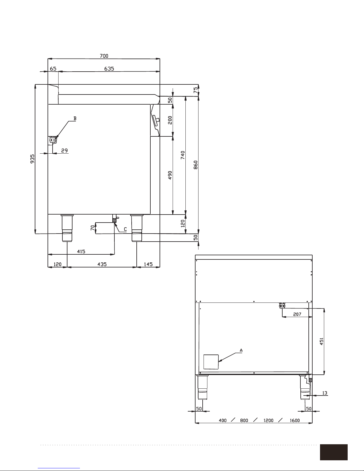
A. Data plate
B. Electrical Connection
C. Gas Connection
FIG.A
4
Ofcine Gullo
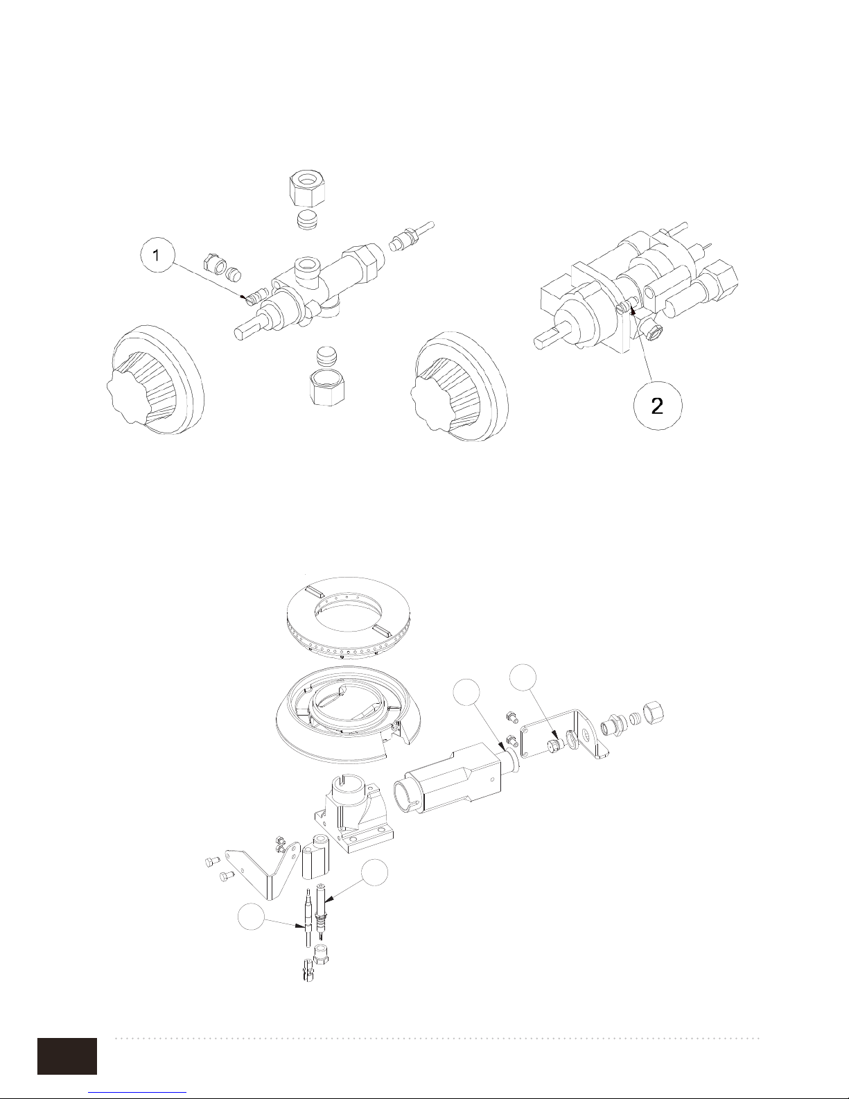
FIG. B
1. Cooking rings by-pass 2. Oven by-pass
FIG. C
1. Injector cooking rings
2. Air regulation
3. Lighting spark plug
4. Thermocouple
FIG. D
1 By-pass fuochi aperti Bypass flamme By-pass feux Cooking rings by-pass By-pass fuegos
2 By-pass forno Backofen Bypass By-pass four Oven by-pass By-pass horno
FIG. F PC…-GP , CF…-GP
(FUOCHI, FLAMME, FEUX, COOKING RINGS, FUEGOS)
1
2
3
4
FIG. H
(FORNO, FOUR, BACKOFEN, OVEN, HORNO)
1
Iniettore forno
Einspritzventil backofen Injecteur four Oven Injector Inyector horno
2
Regolazione aria forno Luftregelung Backofen Réglage d'air four Oven air regulation Regulación aire horno
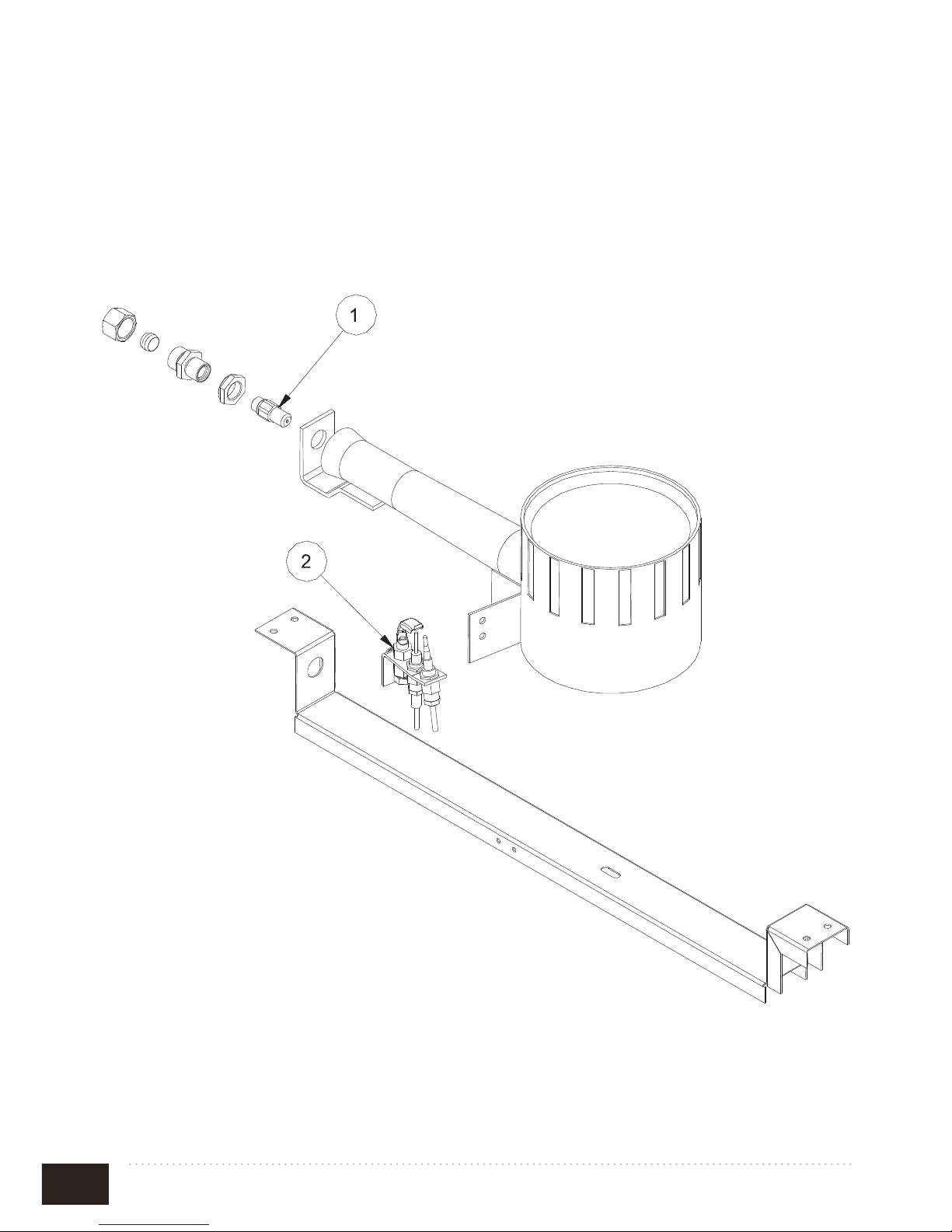
FIG.I
(FORNO, FOUR, BACKOFEN, OVEN, HORNO)
1 Iniettore pilota Einspritzv. ZündBrenner Injecteur veilleuse Pilot Injector Inyector piloto
2 Candela accensione Zündkerze Bougie d'allumage Lighting spark plug Candela encendido
3 Termocoppia Thermoelement Thermocouple Thermocouple Termopar
4 Staffa pilota Bügel Leitflamme Bride veilleuse Pilot bracket Brida del piloto
FIG. J
(FORNO, FOUR, BACKOFEN, OVEN, HORNO)
1
2
1
2
3
4
H
5
Ofcine Gullo
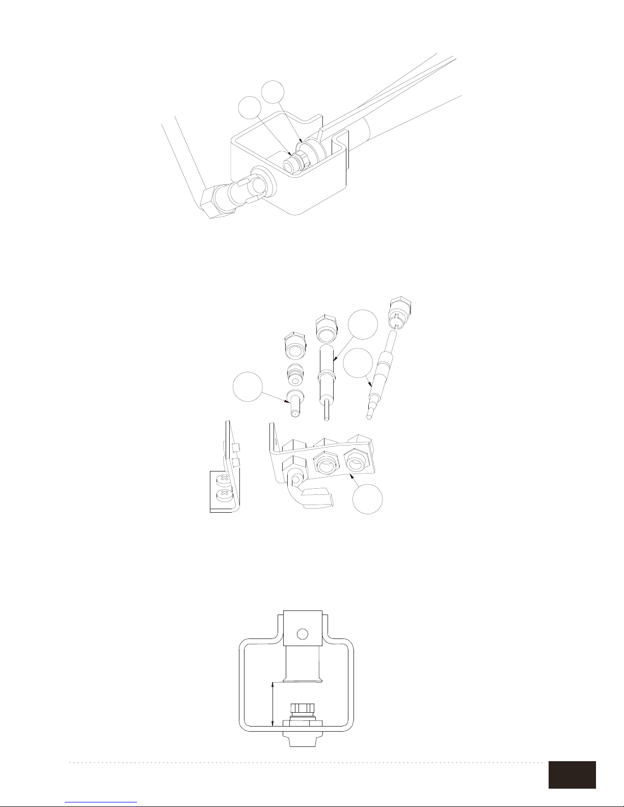
FIG. H
(FORNO, FOUR, BACKOFEN, OVEN, HORNO)
1
Iniettore forno
Einspritzventil backofen Injecteur four Oven Injector Inyector horno
2
Regolazione aria forno Luftregelung Backofen Réglage d'air four Oven air regulation Regulación aire horno
FIG.I
(FORNO, FOUR, BACKOFEN, OVEN, HORNO)
1 Iniettore pilota Einspritzv. ZündBrenner Injecteur veilleuse Pilot Injector Inyector piloto
2 Candela accensione Zündkerze Bougie d'allumage Lighting spark plug Candela encendido
3 Termocoppia Thermoelement Thermocouple Thermocouple Termopar
4 Staffa pilota Bügel Leitflamme Bride veilleuse Pilot bracket Brida del piloto
FIG. J
(FORNO, FOUR, BACKOFEN, OVEN, HORNO)
1
2
1
2
3
4
H
1. Oven injector 2. Oven air regulation
1. Pilot injector
2. Lighting spark plug 3. Thermocouple
4. Pilot bracket
FIG. E (oven)
FIG.D (oven)
FIG. F (oven)
6
Ofcine Gullo
FIG. G
Coup de feu
1. Injector
2. Pilot

7
Ofcine Gullo
FIG. K
FIG. H
8
Ofcine Gullo
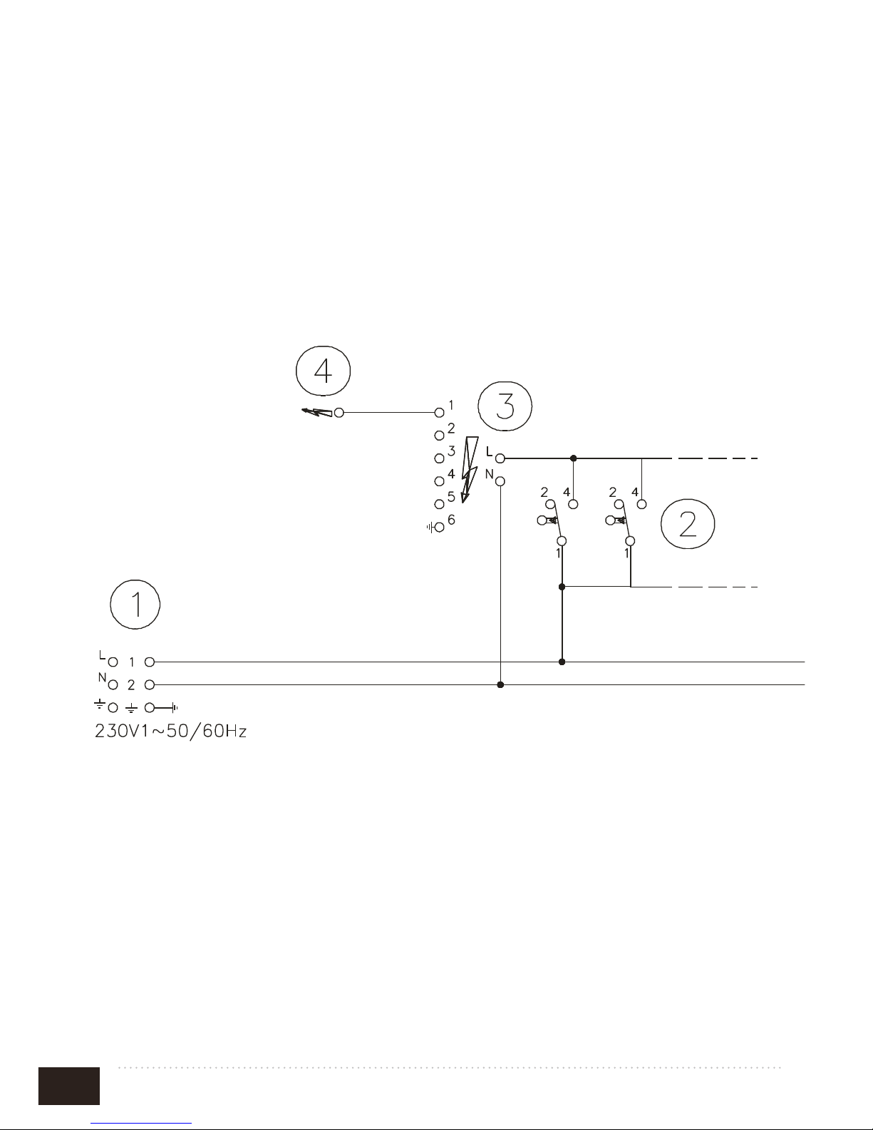
ELECTRICAL SCHEME TOP
1. Electrical connection
2. Push-button starting burner
3/4. Power-station starting burner
FIG. I

9
Ofcine Gullo
WIRING DIAGRAM STATIC OVEN GN2/1
1. Commutator
2. Junction-box
3. Element
4. White light
5. Green light
6. Thermostat
7. Safety thermostat
FIG.L

10
Ofcine Gullo
INDEX
GAS TECHNICAL DATA TABLE ................................................................ 11
ELECTRIC TECHNICAL DATA TABLE ................................................... 11
DECLARATION OF COMPLIANCE .......................................................... 12
INSTALLATION ............................................................................................ 12
CHECKING FOR ADEQUATE VENTILATION ....................................... 12
PIPE FOR GAS CONNECTION .................................................................. 13
ELECTRIC CONNECTION ......................................................................... 13
EQUIPOTENTIAL ......................................................................................... 14
CHECKING HEAT OUTPUT ....................................................................... 14
CHECKING PRIMARY AIR TO THE MAIN BURNERS AND PILOT
NOZZLES ........................................................................................................ 14
“BURNER” TECHNICAL DATA TABLE ................................................... 15
RULES FOR CONVERTING AND INSTALLING
OTHER TYPES OF GAS ............................................................................... 16
CHANGING THE OPEN RING NOZZLES ............................................... 16
SUBSTITUTING THE NOZZLE IN THE OVEN BURNER .................... 16
SUBSTITUTING THE NOZZLE IN THE COUP DE FEU BURNER ..... 16
CHECKING FUNCTIONING ...................................................................... 17
MAINTENANCE ............................................................................................ 17
SPARE PARTS ................................................................................................ 17
INSTRUCTIONS FOR USE .......................................................................... 18
CLEANING AND MAINTENANCE ............................................................ 20
WHAT TO DO IN THE EVENT OF A BREAKDOWN ............................. 21
PROCEDURE TO FOLLOW IF THE APPLIANCE IS NOT .................. 21
GOING TO BE USED FOR SOME TIME .................................................. 21
MAINTENANCE (only for qualied personnel) ......................................... 21
INSTRUCTIONS FOR DISCHARGING GAS EMISSIONS .................... 22

11
Ofcine Gullo
GAS TECHNICAL DATA TABLE
ELECTRIC TECHNICAL DATA TABLE
MODEL
Dimensions
cm
NOMINAL BURNER CAPACITY kW
TOT. NOM.
CAPACITY
kW
Gas coupling
ISO 7-1
Burner
3,5 kW
Burner
5,5 kW
Burner
7,5 kW
Coup de
feu
7 kW
Gas
oven
7,3 kW
Gas
GGS8P
80x70x90h 1 2 1 - 1 29,3 R3/4GM
GES8P
80x70x90h 1 2 1 - - 22 R3/4GM
GGS12P
120x70x90h 1 3 2 - 1 42,3 R3/4GM
GES12P
120x70x90h 1 3 2 - - 35 R3/4GM
GGPS8P
80x70x90h - 1 1 1 1 27,3 R3/4GM
GEPS8P
80x70x90h - 1 1 1 - 20
R1/2GM
3/4GM(1007)
GGPS12P
120x70x90h 1 2 1 1 1 36,3 R3/4GM
GEPS12P
120x70x90h 1 2 1 1 - 29 R3/4GM
MODEL
Dimensions
cm
Power Supply
Tot.
power
(KW)
Max.
absorb
A
Power
supply
cable
mm²
GGS8P
80x70x90h 230V~ 50/60 Hz 0,01 0,04 5x1
GES8P
80x70x90h 400V~3N 50/60 Hz 5 10,4 5x1,5
GGS12P
120x70x90h 230V~ 50/60 Hz 0,01 0,04 5x1
GES12P
120x70x90h 400V~3N 50/60 Hz 5 10,4 5x1,5
GGPS8P
80x70x90h 230V~ 50/60 Hz 0,01 0,04 5x1
GEPS8P
80x70x90h 400V~3N 50/60 Hz 5 10,4 5x1,5
GGPS12P
120x70x90h 230V~ 50/60 Hz 0,01 0,04 5x1
GEPS12P
120x70x90h 400V~3N 50/60 Hz 5 10,4 5x1,5

12
Ofcine Gullo
DECLARATION OF COMPLIANCE
The manufacturer declares that the appliances are compliant with the prescriptions of the
EEC norm 90/396 for the gas part and with norm 73/23 for the electric part.
The installation must be done observing the norms in force particularly concerning room
ventilation and discharging gas emissions.
N.B.: The manufacturer declines any responsibility for direct or indirect damage caused by
improper or incorrect installation, maintenance or use of the appliance and alterations, as in
all the other cases considered in the items of our sales conditions.
INSTALLATION
• The operations for installing, conversions for use with other types of gas and starting
up must be done only by qualied personnel whose qualications comply with the
norms in force.
• Gas installations, the electrical connections and the rooms in which the appliances
are installed must comply with the norms in force in the Country in which the installation is carried out; above all, the appliance must be installed in a well ventilated
room, preferably under an extractor hood, so as to ensure the complete extraction of
gas emissions which are formed during combustion. The air necessary for combustion is 2m3 /h per kW of power installed.
Attention: In accordance with international rules, when connecting the appliance, an automatic device enabling the disconnection of all contacts from the mains, must be installed
above it; this device must have a contacts opening of at least 3 mm.
CHECKING FOR ADEQUATE VENTILATION
Make sure that the air intake into the room where the appliance is installed is sufcient for an
adequate change of air, as specied by regulations in effect.
The appliances installed in buildings open to the public must satisfy the following requirements.
Installation rules
The installation and maintenance of the appliance must be done according to the correct procedures and regulation
texts in use, particularly:
• safety standards for the prevention of re and panic.
Connection and installation of appliance, ventilation and exhaust removal systems, shall be done
according to the Manufacturer’s instructions and by qualied technicians and according to the
regulations in effect. The electric wiring shall conform to the regulations in effect.
All re prevention codes shall be observed.
a) General indications (Rules valid for GB only)
- For all appliances:
Gas safety Regulations, 1984; Health and safety at Work Act, 1974 Codes of Practice, BS 8173,
1982, The Building

13
Ofcine Gullo
Regulations 1985; The Building Standards Regulations, 1981, the IEE Regulations and the bylaws of the local Water Undertaking.
The local gas Region or LPG supplier and the local authority and the relevant recommendation
of the British Standards (latest editions) concerned.
The installation, transformation and repair of appliances for professional kitchens as well as removal due to malfunction, and the supply of gas, may be made only by means of a maintenance
contract stipulated with an authorized sales ofce and in observance of technical regulations.
The appliance can be installed by itself or in a series side by side with appliances produced by us.
There must be a minimum distance of at least 10 cm between the appliance and the sides of the
nearby cabinets made of inammable material.
Take suitable measures to guarantee thermal insulation of the inammable sides, such as, for
example, the installation of protection against radiation.
The appliances must be installed in a suitable manner, observing the safety standards.
The small feet are adjustable to level the appliance.
PIPE FOR GAS CONNECTION
The gas connection must be done with steel or copper pipes, or otherwise with exible steel
pipes in compliance with the national norms, if any exist. Each appliance must be provided
with a cut-off cock for rapid interruption of the gas supply. Once the appliance has been
installed, it is necessary to check for gas leaks for the pipe ttings; do not use a ame for
this purpose but a non-corrosive substance such as soapy water or foamy substances as
contained in leaknder sprays. All our appliances undergo careful testing: the type of gas,
the operating pressure and the category are indicated on the data plate.
NB: The year of the appliance manufacture is shown in item “N” on the data plate. The rst
two numbers (e.g. 08..) represent the year of manufacture.
ELECTRIC CONNECTION
The appliance is supplied without the connection cable; to install it, proceed in the fol-
lowing way:
- Remove the back panel
- Push the connection cable through the cable channel, connect the conductor wires to the
corresponding terminals in the junction box and x them into place.
- Block the cable with the cable blocker, and reassemble the panel. The earth wire must be
longer than the others so that if the cable blocker should break, it will disconnect after the
tension wires.
N.B. The connection cable must have the following characteristics: it must be type
H05RN-F and must have an adequate section for the power of the appliance (see tech-
nical data table).

14
Ofcine Gullo
EQUIPOTENTIAL
The appliance must be connected to an equipotential system.
The connection screw is positioned at the back of the appliance and is identied by the
symbol .
Attention! The manufacturer will neither be held responsible for, nor will give any
compensation during the guarantee period for any damage caused, and which is due to
inadequate installations not compliant with the instructions.
CHECKING HEAT OUTPUT
The appliances must be checked in such a way as to verify that the heat output is correct:
• The heat output (thermal power) is indicated on the data plate of the appliance;
• Firstly, check that the appliance can be used with the type of gas supplied; then
check that the indication on the plate corresponds to the gas to be used. For converting to another type of gas, check that the type of gas complies with what is
stated in this instruction manual.
The pressure is read with a gauge (minimum resolution of 0.1 mbar) inserted in the relative
pressure outlet. (gure 1 item C).
Remove the hermetically closed screw and insert the gauge pipe.
After reading, put back the screw tightening it hermetically and check for pressure leaks.
Connection for liquid gas G30/G31
The connection pressure for liquid gas is 30 mbar with butane and 37 mbar with propane.
Check the plate, read the pressure and verify that the description of the nozzle installed
corresponds to the one supplied by the manufacturer.
Connection with natural gas H G20
The connection pressure for natural gas is 20 mbar.
Check the plate, read the pressure and verify that the description of the nozzle installed
corresponds to the one supplied by the manufacturer.
CHECKING PRIMARY AIR TO THE MAIN BURNERS AND PILOT NOZZLES
All the burners are tted with an air regulator by means of which the primary air can be varied
thanks to an adjustable bush that can be locked with a screw. In the “Burner Technical Data”
table you will nd the approximate values for the “h” parameter (primary air). The ow of
primary air must be regulated so there is no detachment of the ame when the burner is cold
or a return of the ame when the burner is hot.
The pilot air is regulated when the appliance is tested and inspected for the gas it is set for.
If you are going to change to a different type of gas, regulate the air by means of the adju-
sting bush until the ame stops sputtering and becomes an intense blue colour.

15
Ofcine Gullo
“BURNER” TECHNICAL DATA TABLE
Burner max 3,5 kW- min. 1,15 kW
12,68 kWh/kg
G30
BUTANE
30 mbar
12,87kWh/kg
G31
PROPANE
37 mbar
9,45 kWh/m3st.
G20
NATURAL GAS H
20 mbar
Burner injector 1/100 mm
Min. output adjustment 1/100 mm
Pilot Injector 1/100 mm
Consumption
Primary air h=mm
90
50
20
kg/h 0,276
open
90
50
20
kg/h 0,272
open
145
adjustable
35
m3 st./h 0,370
open
Burner max 5,5 kW- min. 1,55 kW
Burner injector 1/100 mm
Min. output adjustment 1/100 mm
Pilot Injector 1/100 mm
Consumption
Primary air h=mm
115
60
20
kg/h 0,434
open
115
60
20
kg/h 0,427
open
175
adjustable
35
m3 st./h 0,582
20
Burner max 7,5 kW- min. 2,5 kW
Burner injector 1/100 mm
Min. output adjustment 1/100 mm
Pilot Injector 1/100 mm
Consumption
Primary air h=mm
135
75
20
kg/h 0,591
20
135
75
20
kg/h 0,582
20
205
adjustable
35
m3 st./h 0,794
20
Coup de feu
Burner max 7 kW- min. 4 kW
Burner injector 1/100 mm
Min. output adjustment 1/100 mm
Pilot Injector 1/100 mm
Consumption
130A
100
20
kg/h 0,552
130A
100
20
kg/h 0,544
195
adjustable
35
m3 st./h 0,740
Oven Burner max 7,3 kW- min. 2,2 kW
Burner injector 1/100 mm
Min. output adjustment 1/100 mm
Pilot Injector
Consumption
Primary air h=mm
145
75
1x19
0.570 kg/h
12
145
75
1x19
0.570 kg/h
12
205
adjustable
1x27
0.772 m3 st./h
12
Oven Burner max 11 kW- min. 3,5 kW
Burner injector 1/100 mm
Min. output adjustment 1/100 mm
Pilot Injector
Consumption
Primary air h=mm
175
100
1x19
0.859 kg/h
13
175
100
1x19
0.859 kg/h
13
270
adjustable
1x27
1.164 m3 st./h
13

16
Ofcine Gullo
RULES FOR CONVERTING AND INSTALLING OTHER TYPES OF GAS
Our appliances are tested and regulated for liquid gas (see plate inside).
The conversion or adaptation to another type of gas must be carried out by a specialized
technician. The nozzles for the various types of gas are in a packet supplied with the appliance and are marked in hundredths of mm (see the technical data table).
CHANGING THE OPEN RING NOZZLES
Main nozzles
Take the rungs off, remove the burners and trays, with a size 12 spanner substitute the nozzles with
the appropriate ones, regulate the primary air (h) (see the “burner” technical data table) unscrewing
the securing screw. Once regulated, tighten the screw, adjust the minimum ame by turning the screw
to the right or left until the thermal power reaches 1,15 kW for the 3,5 kW burner, 1,55 for the 5,5 kW
burner and 2,5 kW for the 7 kW burner.
Warning: If liquid gas is being used the minimum adjustment screw must be locked right down.
SUBSTITUTING THE NOZZLE IN THE OVEN BURNER
To substitute the oven burner, proceed as follows:
• Remove the oven bottom (oor);
• Unscrew the xing screws from the burner nozzle protection.
• Substitute the nozzle, using a suitable spanner (see “burners” technical data table).
• Regulate the air regulation bush to the corresponding value in the “technical data”
table by unscrewing the xing screw with relative jam nut, regulate minimum output
by turning the screw to the right or to the left until the thermal power reaches 2,2 kW
for the burner of 7,3 kW and 3,5 kW for the burner of 11 kW; this procedure is only
possible after having let the oven burner work at maximum output for about 20 minutes
(knob in pos. 300).
• After this procedure, put back the burner nozzle protection.
• Substitute the pilot nozzle, using a suitable spanner.
After regulating, check lighting, at both maximum and minimum output. Make sure
that, when changing rapidly from minimum to maximum output, the ame does not
present any problems and that it doesn’t go out, when closing or opening the oven door
quickly.
Warning: For functioning with liquid gas, screw down the regulating screw completely.
SUBSTITUTING THE NOZZLE IN THE COUP DE FEU BURNER
Remove the panel and with a suitable spanner substitute the nozzle with another, suitable one.
Adjust the minimum ame by turning the by-pass screw either to the right or to the left until
heat output reaches 4 kW.
The primary air of the all plate burner does not need adjusting.
Attention: If liquid gas is used, the minimum ame adjustment screw must be screwed right
down.

17
Ofcine Gullo
CHECKING FUNCTIONING
• The appliance contains the instructions necessary for use.
• Check the appliances for gas leaks.
• Check the lighting and ame of the main burner.
• We urge the user to follow the instructions when using the appliance.
MAINTENANCE
With prolonged use of the appliance, it is essential to carry out regular maintenance for
the safe functioning of the appliance; we therefore recommend drawing up a contract for
after sales service. Maintenance must be done only by specialized personnel, observing the
norms in force and our indications.
SPARE PARTS
Coup de feu:
It is possible to substitute the spark plug cock, thermocouple and burner after having removed
the front panel.
Open rings:
The cocks can be changed by removing the front panel; to change the thermocouples and
burners you have to remove the rungs and trays.
Gas oven:
the gas-cock, timer, thermocouples, burners and ignition plugs can be changed by accessing
them inside the oven and/or by removing the bottom oven panel or control panel.

18
Ofcine Gullo
INSTRUCTIONS FOR USE
Attention! The appliance must only be used under surveillance.
LIGHTING AND ADJUSTING THE BURNERS
On the front panel, above each knob, there is a symbol which
indicates to which burner the knob corresponds.
To light, turn the knob to the left from position “0” to the
symbol (see gure); keep it pushed down and press the button with
the symbol until the gas lights.
The knob must be kept pushed down for a few seconds and then
released. The ame may go out, in which case it is necessary to
repeat the procedure. By turning to the
position, the burner is
brought to the minimum. To put out the burner, turn the knob back
into the “0” position.
LIGHTING AND ADJUSTING THE COUP DE FEU
On the front panel, above each knob, the burner it corresponds to
is indicated by the index
Use a lighter to light the pilot ame: turn the knob to the left, from
the “0” position to the sign (see gure), hold it down and light
the gas.
Keep the knob pressed a few second and then let it go.
If the ame goes out you have to repeat the procedure.
By turning the knob round to the position the burner is at
maximum.
By turning the knob round to the position the burner is at
minimum. To switch off, move the knob back into position " 0".

19
Ofcine Gullo
LIGHTING AND REGULATING GAS OVEN BURNER
To light, turn the knob to the left from position “0” to the
symbol (see gure);
keep it pushed down and press the button with the symbol until
the gas lights.
It is possible to check the ame through the inspection hole on
the oven oor (bottom); after a few seconds, release the knob. If
the ame goes out, repeat the operation. Turn the knob into the
position of the desired temperature.
To turn off the oven, turn the knob to the right, into position “0”
Attention! When the oven is on, the door must not remain open
because it could heat and damage the knobs.
LIGHTING AND REGULATING THE ELECTRIC OVEN
Turn the control knob to the right and set the temperature wanted.
To turn the oven off, turn the knob to the left to position 0.
To turn the oven on, turn the selector knob (see gure) to the right
or left into one of the following positions
Top + bottom heating element
Bottom heating element
Top heating element
Caution: when the oven is on the door must be kept shut otherwise
the knobs and protection sheet could get hot and be damaged.

20
Ofcine Gullo
CLEANING AND MAINTENANCE
Attention! During cleaning, do not wash the external parts of the appliance with direct
sprays of water or with high pressure.
After every use, clean the appliance thoroughly. Daily cleaning after switching off the appliance ensures the perfect functioning and long life of the appliance.
Before starting to clean the appliance, disconnect the power supply. The parts in steel must
be washed with hot water and neutral detergent, then rinsed thoroughly in order to eliminate
all traces of detergent; after which, dried with a dry cloth.
Do not use abrasive or corrosive detergents.
The enamelled parts should be washed with soapy water.
After cleaning, turn the elements back correctly.
Important: As well as ordinary cleaning and maintenance, it is advisable to have the installation checked by an installer at least once a year.
It is therefore suggested to draw up an after-sales assistance contract.
CLEANING BURNISHED BRASS SURFACES
No synthetic protective varnishes have been used to obtain the special burnishing effect
on the burnished brass details in order to avoid spoiling the beauty of the brass with an
articial patina. The antique nish of the surface is the result of natural oxidation that has
simply been accelerated. All the natural antique nish brass surfaces can be cleaned with
any kitchen degreasing detergent, accompanied by the use of an abrasive scouring pad (the
green colored type used for washing dishes). It is recommended that the metal be rubbed,
uniformly applying light pressure, until the desired effect is achieved.
The brass details should then be dried.
Do not use polish as this is suitable for maintaining the gloss but not the antique nish and
could result in an effect that is not compliant with our products. Any spots that may appear
over time on the burnished brass surfaces should be considered as a desirable and particular
characteristic of our craft metal working processes.
CLEANING CHROMIUM-PLATED BRASS SURFACES
No synthetic varnishes have been used to obtain the special polish on the chromium-plated
brass details in order to avoid spoiling the beauty of the chromium plating with an articial
patina. All the chromium-plated surfaces should be cleaned, where necessary, with a soft,
possibly micro-ber cloth, combined with metal polishing products, if required. Do not use
abrasive pads.

21
Ofcine Gullo
CLEANING SATIN FINISH NICKEL-PLATED BRASS SURFACES
No synthetic varnishes have been used to obtain the special nickel-plating on the satin
nish nickel-plated brass details in order to avoid spoiling the beauty of the nickelplated, satin nished solid brass with an articial patina. All the nickel-plated and
satin nished brass surfaces should be cleaned, where necessary, with a soft, possibly
micro-ber cloth, combined with a neutral detergent, if required. Do not use abrasive
pads.
CLEANING THE VARNISHED SURFACES
All the varnished surfaces should be cleaned using a neutral detergent and, where
necessary, a soft, possibly micro-ber cloth. Do not use abrasive pads or any other
chemical products.
CLEANING BRUSHED STEEL SURFACES
All the brushed steel surfaces should be cleaned using degreasing products or products
specically designed to be used on steel and, where necessary, extra-ne steel wool
or extra-thin sandpaper.
WHAT TO DO IN THE EVENT OF A BREAKDOWN
Turn off the gas tap and notify the after sales service.
PROCEDURE TO FOLLOW IF THE APPLIANCE IS NOT
GOING TO BE USED FOR SOME TIME
Turn off the gas tap and clean the appliance as specied above.
MAINTENANCE (only for qualied personnel)
Any kind of maintenance must only be done by qualied personnel. Before carrying
out maintenance,remove the plug or switch off the switch above the appliance.

22
Ofcine Gullo
INSTRUCTIONS FOR DISCHARGING GAS EMISSIONS
Type “A” Appliances (See data plate)
Type “A” appliances must discharge the products of combustion into extractor hoods or
similar devices connected to and efcient chimney, or directly outside.
(Natural Discharge) Fig.1.
If there is no hood, as an alternative, an air extractor connected directly to the outside
is acceptable, (Forced Discharge) Fig.2, but its capacity must not be inferior to what is
established in item 4.3 of the UNI-CIG norm 8723.
In the event of forced discharge
The gas supply to the appliance, must be directly interlocked to the system and cut off
automatically if its capacity drops below the values prescribed by item 4.3 of the UNI-CIG
norm 8723.
Supplying the appliance with gas again must only be possible manually.
NATURAL DISCHARGE FORCED DISCHARGE
1. Extractor hood 1. Extractor hood
2. Interlocking
Fig.1 Fig.2

23
Ofcine Gullo

WWW.OFFICINEGULLO.COM
V 1.0 - 10. 17
OFFICINE GULLO S.R.L.: via della Torricella 29, 50012 Antella - Bagno a Ripoli (FI)
Tel. +39 055 6560324 / 621807 - Fax: + 39 055 620670 - info@officinegullo.com
en
INTERNATIONAL
 Loading...