

INSTRUCTIONS
for installation and use
PASTA COOKER FOR
RESIDENTIAL AND PROFESSIONAL USE
CVCS4G CVCS6G CVS4G CVS6G

2
Ofcine Gullo
CAUTION
1. These safety directions apply to different kinds of appliances. Please identify correctly the specic appliance in
your possession (check the tag showing the characteristics).
2. Before using the appliance, read the instruction manual carefully, as it contains important safety information
on the proper installation, use and maintenance of the appliance. Please keep the instruction manual for further
reference.
3. The appliance’s electrical safety is guaranteed only if the electrical system is earthed in accordance with the
relevant regulations. It is of the utmost importance to follow such regulations; when in doubt, please consult a
qualied electrician to have the electrical system thoroughly checked. The manufacturer declines all responsibility for damage caused by a badly-earthed electrical system
4. Before connecting the appliance, make sure that the appliance’s technical characteristics shown on the tag corre spond to those of the electrical system and gas distribution network.
5. Make sure that the electrical system and sockets can handle the appliance’s maximum power consumption as
shown on the tag. When in doubt, please consult a qualied electrician.
6. The appliance should be connected to the electric supply line by means of an omnipolar switch with a minimum
contact opening of 3 mm
7. If the power socket is not compatible with the plug, replace the socket with a proper one and consult a qualied
electrician to make sure that the cable size can handle the appliance’s maximum power consumption. The use of
adapters, multiple power boards and extension cords is not recommended.
8. When not in use, switch off the general power supply to the appliance and close the gas supply valve.
9. Do not obstruct the appliance’s cooling or heat dissipation vents.
10. In case of damage to the appliance’s power cord, it must be replaced exclusively by the manufacturer’s authorized service center.
11. The appliance must be used only for the purposes for which it has been expressly designed (cooking). All other
uses (such as the heating of a room) are considered inappropriate and therefore dangerous. The manufacturer
declines all responsibility for damage resulting from improper use of the appliance.
12. The use of any electric appliance implies the observance of some basic rules. More specically:
A. Do not touch the appliance with wet or damp hands or feet;
B. Do not use the appliance with bare feet;
C. Avoid the use of extension cords and, if necessary, take all precautions;
D. Do not pull the power cord to disconnect the plug from the power socket;
E. Do not leave the appliance exposed to atmospheric agents (rain, sun, etc.);
F. F. Do not allow children or untrained persons to use the appliance.
13. Before cleaning the appliance or performing maintenance work, disconnect the appliance by pulling the plug out
of the power socket or turning off the main switch.
14. In case of failure or malfunction, turn the appliance off, close the gas supply valve and do not attempt to carry
out any repairs, which must be done exclusively by an authorized service center.
Request the use of original spare parts only . Failure to comply with the above recommendations may compromise
the appliance’s safety
3
Ofcine Gullo
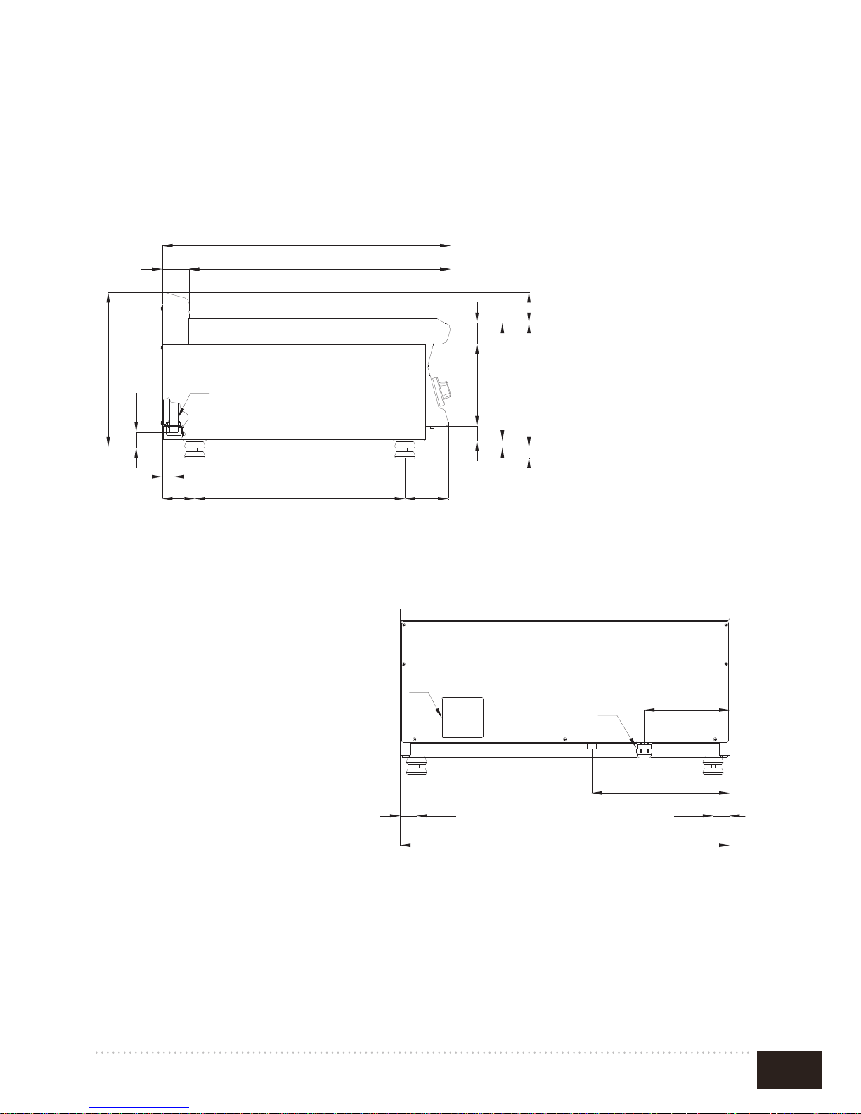
CVS4G - CVS6G
FIG.A
65 635
700
28
79 511 105
35
200 50
285
17
302
25
75
37
377
335
4040
207
400 / 800 / 1200 / 1600
B
C
A
635
700
335
4040
207
400 / 800 / 1200 / 1600
B
A
A. Data plate
C. Gas Connection R 1/2GM
4
Ofcine Gullo
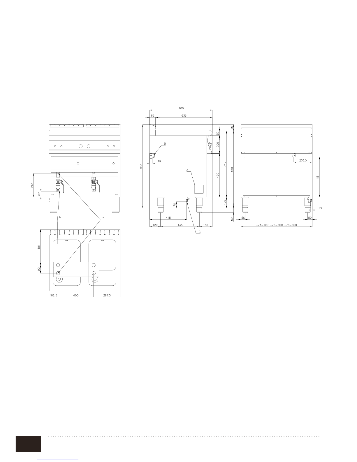
CVSC4G
A. Data Plate
C. Gas Connection ISO 7-1 R1/2GM
D. Water connection R 1/2GM
E. Water drainage R 1GF
FIG.B
5
Ofcine Gullo
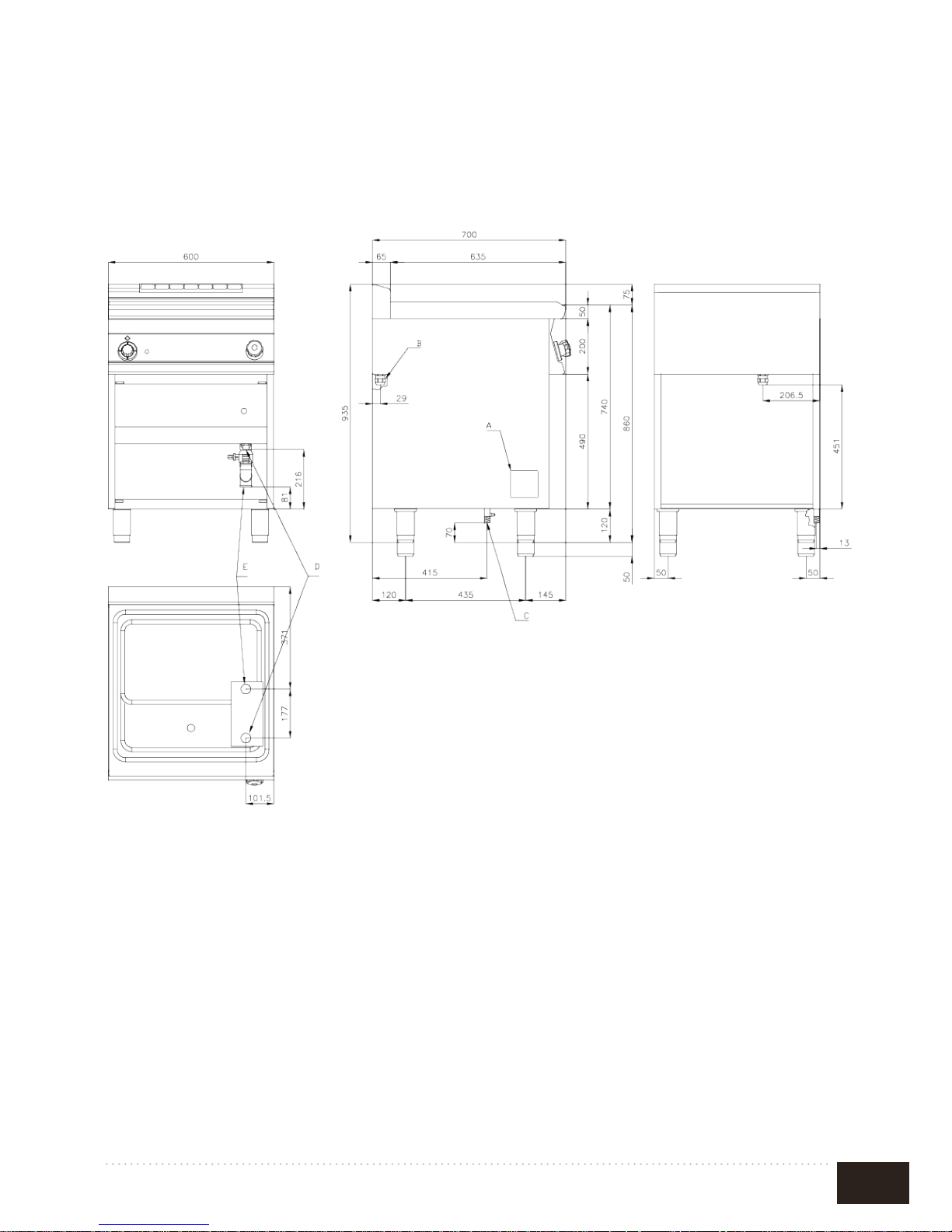
CVSC6G
A. Data Plate
C. Gas Connection ISO 7-1 R1/2GM
D. Water connection R 1/2GM
E. Water drainage R 1GF
FIG.B2
6
Ofcine Gullo
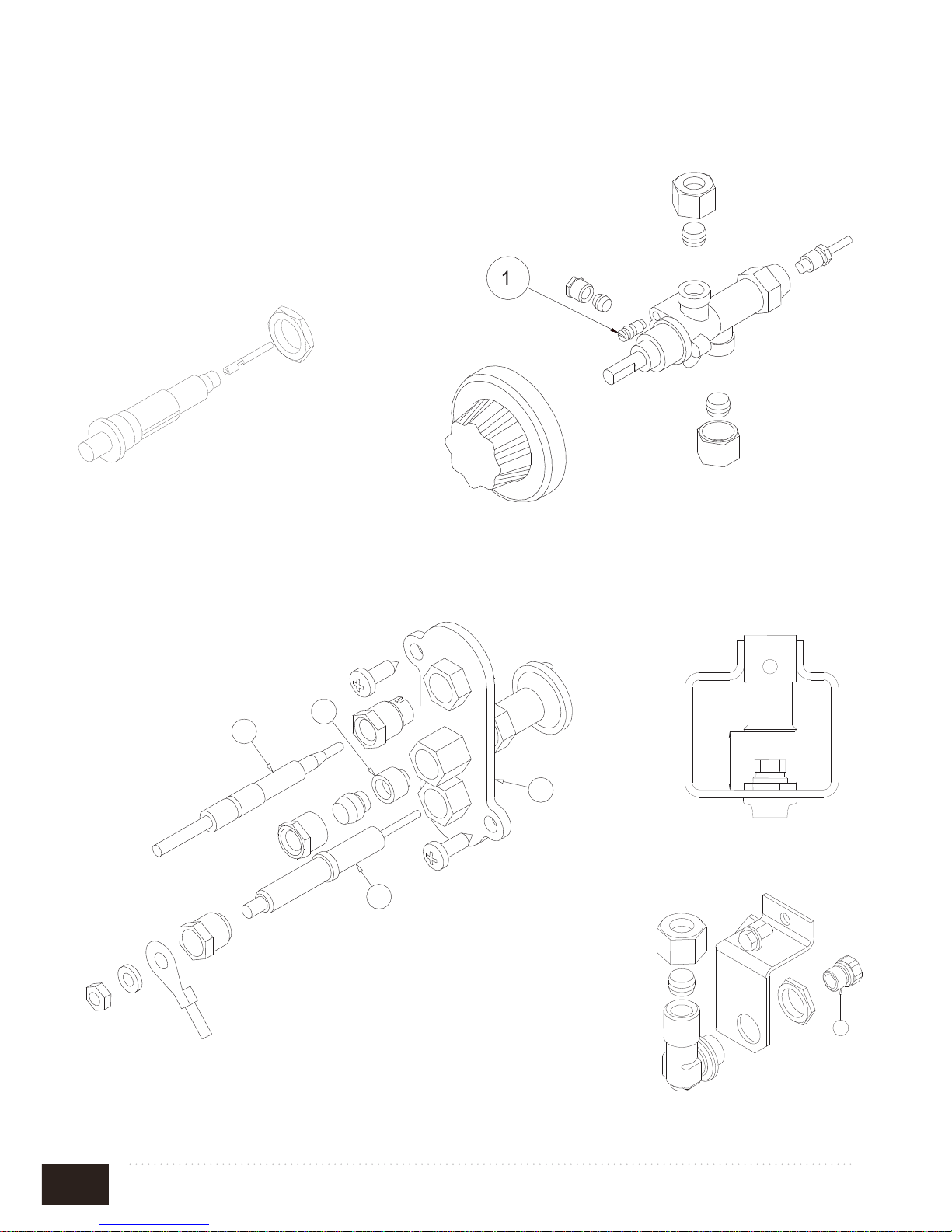
FIG.C
Piezoelectric device
Bypass
FIG.D
2
3
4
1
1
H
Injector
1. Bride
2. Pilot
3. Thermocouple
4. Spark plug
7
Ofcine Gullo
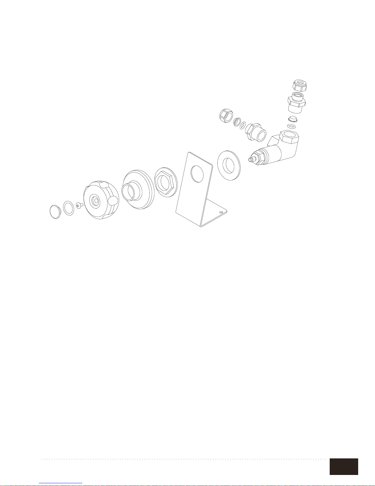
FIG.E
WATER FILLING T AP
8
Ofcine Gullo
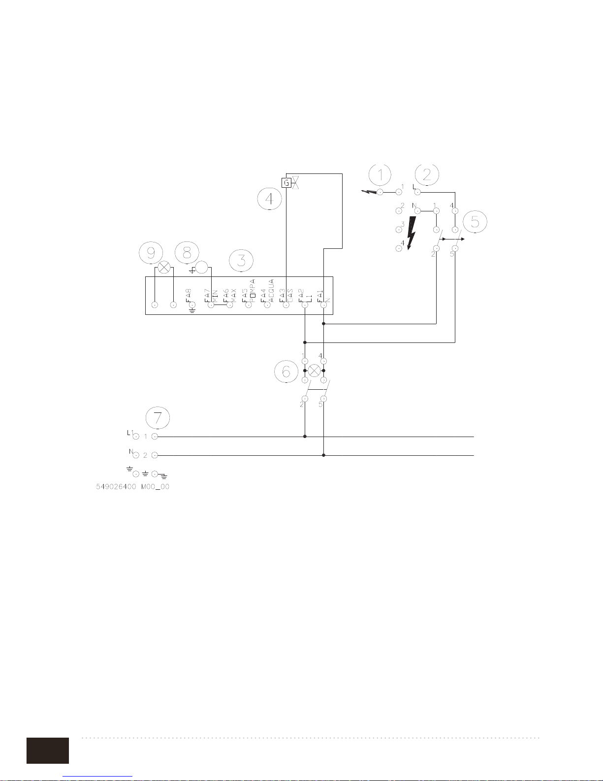
FIG.E
WIRING DIAGRAM MOD. CVC..
SCHEMA ELETTRICO – SCHALTPLAN – SCHEMA ELECTRIQUE
WIRING DIAGRAM – ESQUEMA ELECTRICO
CP...
549026400 M00_00
230V~ 50/60 Hz
1. Lighting spark plug
2. Power-station starting burner
3. Water safety unit
4. Gas solenoid valve
5. Push-button starting burner
6. Interrupteur bipolaire
7. Power terminal block
8. Level Probe
9. Red warning light

9
Ofcine Gullo
INDICE
DECLARATION OF COMPLIANCE ..........................................................10
TECHNICAL GAS SCHEME
.......................................................................10
ELECTRICAL TECHNICAL DATA TABLE
..............................................10
INST ALLING THE APPLIANCE
................................................................10
CHECKING FOR ADEQUA TE VENTILA TION
.......................................11
PIPE FOR GAS CONNECTION
..................................................................11
ELECTRIC CONNECTION (mod. CVC...)
................................................12
EQUIPOTENTIAL
.........................................................................................12
CHECKING HEAT OUTPUT
.......................................................................12
“BURNERS” TECHNICAL DAT A T ABLE
.................................................13
CHECKING PRIMARY AIR IN MAIN BURNERS
..................................14
RULES FOR CONVERTING AND INSTALLING OTHER
TYPES OF GAS
..............................................................................................14
SUBSTITUTING THE NOZZLE IN THE MAIN BURNER
.....................14
SUBSTITUTING THE NOZZLE IN THE PILOT BURNER
...................14
CHECKING FUNCTIONING
......................................................................14
MAINTENANCE
............................................................................................15
SPARE PARTS
................................................................................................15
WATER SUPPLY CHARACTERISTICS
....................................................15
WATER CONNECTION AND DRAINAGE
...............................................15
STARTING UP
................................................................................................16
LIGHTING AND ADJUSTING THE MAIN BURNER - MOD. CVS...
...16
OPERATION MOD. CVC…
.........................................................................16
TURNING OFF THE APPLIANCE
.............................................................17
EMPTYNG THE TUB
....................................................................................17
SAFETY THERMOSTAT MOD.CVS…
......................................................17
ANOMALIES
..................................................................................................17
OBSERVA TIONS AND ADVICE
..................................................................17
CLEANING AND MAINTENANCE
............................................................18
Cleaning burnished brass surfaces
................................................................18
Cleaning chromium-plated brass surfaces
...................................................18
Cleaning satin nish nickel-plated brass surfaces
.......................................19
Cleaning the varnished surfaces
....................................................................19
Cleaning brushed steel surfaces
.....................................................................19
WHAT TO DO IN THE EVENT OF A BREAKDOWN
.............................19
PROCEDURE TO FOLLOW IF THE APPLIANCE IS NOT
..................19
GOING TO BE USED FOR SOME TIME
..................................................19
MAINTENANCE (only for qualied personnel)
.........................................19
INSTRUCTIONS FOR DISCHARGING GAS EMISSIONS
....................20

10
Ofcine Gullo
TECHNICAL GAS SCHEME
ELECTRICAL TECHNICAL DATA TABLE
MODEL Dimensions
Nominal
Power
TOT. kW
Water lling
Water
drainage
Gas Conn.
ISO R7
CVS4G
40 x 70 x 29h 6 - - R 1/2”GM
CVS6G
60 x 70 x 29h 9 - - R 1/2”GM
CVCS4G
40 x 70 x 90h 9,5 R 1/2”GM R 1GF R 1/2”GM
CVCS6G
60 x 70 x 91h 13,95 R 1/2”GM R 1GF R 1/2”GM
MODEL Power Supply
Max
Absorbtion
(A)
Max Power
(kW)
POWER
SUPPLY
CABLE
(Silicone)
CVCS4G
230V~50/60
Hz
0,1 0,02 3x 1
CVCS6G
230V~50/60
Hz
0,1 0,02 3x 1
DECLARATION OF COMPLIANCE
The manufacturer declares that the appliances are compliant with the prescriptions of the
EEC norm 90/396. The installation must be done observing the norms in force particularly
concerning room ventilation and discharging gas emissions.
N.B.: The manufacturer declines any responsibility for direct or indirect damage caused by
improper or incorrect installation, maintenance or use of the appliance and alterations, as in
all the other cases considered in the items of our sales conditions.
INST ALLING THE APPLIANCE
• The operations for installing, conversions for use with other types of gas and starting
up must be done only by qualied personnel whose qualications comply with the
norms in force.
• The gas installation, the electrical connections and the rooms in which the
appliances are installed must comply with the norms in force in the Country in which
the installation is carried out; above all, the appliance must be installed in a well
ventilated room, preferably under an extractor hood, so as to ensure the complete
extraction of gas emissions which are formed during combustion. The air necessary
for combustion is 2m3/h per kW of power installed.

11
Ofcine Gullo
CHECKING FOR ADEQUA TE VENTILA TION
Make sure that the air intake into the room where the appliance is installed is sufcient for an
adequate change of air, as specied by regulations in effect.
The appliances installed in buildings open to the public must satisfy the following requirements.
Installation rules
The installation and maintenance of the appliance must be done according to the correct
procedures and regulation
texts in use, particularly:
• safety standards for the prevention of re and panic.
Connection and installation of appliance, ventilation and exhaust removal systems, shall be done
according to the Manufacturer’s instructions and by qualied technicians and according to the
regulations in effect. The electric wiring shall conform to the regulations in ef fect.
All re prevention codes shall be observed.
a) General indications (Rules valid for GB only)
- For all appliances:
Gas safety Regulations, 1984; Health and safety at Work Act, 1974 Codes of Practice, BS 8173,
1982, The Building
Regulations 1985; The Building Standards Regulations, 1981, the IEE Regulations and the bylaws of the local Water Undertaking.
The local gas Region or LPG supplier and the local authority and the relevant recommendation
of the British Standards (latest editions) concerned.
The installation, transformation and repair of appliances for professional kitchens as well as
removal due to malfunction, and the supply of gas, may be made only by means of a maintenance
contract stipulated with an authorized sales ofce and in observance of technical regulations.
The appliance can be installed by itself or in a series side by side with appliances produced by us.
There must be a minimum distance of at least 10 cm between the appliance and the sides of the
nearby cabinets made of inammable material.
Take suitable measures to guarantee thermal insulation of the inammable sides, such as, for
example, the installation of protection against radiation. The appliances must be installed in
a suitable manner, observing the safety standards. The small feet are adjustable to level the
appliance.
PIPE FOR GAS CONNECTION
The gas connection must be done with steel or copper pipes, or otherwise with exible steel
pipes in compliance with the national norms, if such exist. Each appliance must be provided
with a cutoff cock for rapid interruption of the gas supply.
Once the appliance has been installed, it is necessary to check for gas leaks from the pipe
ttings; do not use a ame for this purpose but a non-corrosive substance such as soapy
water or the specic leak-nder sprays. All our appliances undergo careful testing: the type
of gas, the operating pressure and the category are indicated on the data plate.

12
Ofcine Gullo
ELECTRIC CONNECTION (mod. CVC...)
The appliance is supplied without the connection cable.
To install the power supply cable, proceed as follows:
• Disconnect the power supply.
• Remove the bottom panel.
• Push the connection cable through the cable blocker, connect the conductor wires to the
corresponding terminals in the junction box and x them into place.
• Block the cable with the cable blocker , and reassemble the front panel. The earth wire must
be longer than the others so that if the cable blocker should break, it will disconnect after
the tension wires.
N.B. The connection cable must have an adequate section for the power of the appliance and be
resistant to a temperature of at least 150°C (see technical data table).
EQUIPOTENTIAL
The appliance must be connected to an equipotential system. The connection screw is positioned
at the back of the appliance and is identied by the symbol
.
Attention: The manufacturer will neither be held responsible for , nor will give any compensation
during the guarantee period for any damage caused, and which is due to inadequate installations
not compliant with the instructions.
CHECKING HEAT OUTPUT
The appliances must be checked in such a way as to verify that the heat output is correct:
• The heat output (thermal power) is indicated on the data plate of the appliance.
• Firstly, check that the appliance can be used with the type of gas supplied; then
check that the indication on the plate corresponds to the gas to be used. For converting to another type of gas, check that the type of gas complies with what is
stated in this instruction manual.
The pressure is read with a gauge (minimum resolution of 0.1 mbar) inserted in the relative
pressure outlet.
Remove the hermetically closed screw and connect the gauge pipe.
After reading, put back the screw, tightening it hermetically and check for leaks.
Connection for liquid gas G30/G31
The connection pressure for liquid gas is 30 mbar with butane and 37 mbar with propane.
Check the plate, read the pressure and verify that the description of the nozzle installed
corresponds to the one supplied by the manufacturer.
Connection with natural gas H G20
The connection pressure for natural gas is 20 mbar.
Check the plate, read the pressure and verify that the description of the nozzle installed
corresponds to the one supplied by the manufacturer.

13
Ofcine Gullo
“BURNERS” TECHNICAL DATA T ABLE
CVS4G
Burner 6 kW min. 2,75 kW
12,68 kWh/kg
G30
BUTANE
30 mbar
12,87kWh/kg
G31
PROPANE
37 mbar
9,45 kWh/m
3
st.
G20
NATURAL
GAS
20 mbar
Burner Injector 1/100 mm
Min. output adjustment 1/100 mm
Pilot Injector
Consumption
Primary air h =mm
125
75
19
kg/h 0,473
15
125
75
19
kg/h 0,466
15
185
adjustable
35
m³ st./h 0,635
15
CVS6G
Burner 9 kW min. 3,7 kW
Burner Injector 1/100 mm
Min. output adjustment 1/100 mm
Pilot Injector
Consumption
Primary air h =mm
150
85
19
kg/h 0,710
20
150
85
19
kg/h 0,699
20
230
adjustable
35
m³ st./h 0,952
15
CVCS4G
Burner 9,5 kW
Burner Injector 1/100 mm
Min. output adjustment 1/100 mm
Pilot Injector
Consumption
160
100
25
kg/h 0,749
160
100
25
kg/h 0,738
235
adjustable
41
m³st./h 1,005
CVCS6G
Burner 13,95 kW
Burner Injector 1/100 mm
Min. output adjustment 1/100 mm
Pilot Injector
Consumption
2x130
130
25
kg/h 1,100
2x130
130
25
kg/h 1,084
2x205
adjustable
41
m³st./h 1,476

14
Ofcine Gullo
CHECKING PRIMARY AIR IN MAIN BURNERS
All the burners are provided with a bush for regulating the primary air which must be
positioned at a distance h indicated in the technical data table.
RULES FOR CONVERTING AND INSTALLING OTHER TYPES OF GAS
Our appliances are tested and regulated for liquid gas (see plate inside).
The conversion or adaptation to another type of gas must be carried out by a specialized
technician. The nozzles for the various types of gas are in a packet supplied with the
appliance and are marked in hundredths of mm (see the technical data table).
SUBSTITUTING THE NOZZLE IN THE MAIN BURNER
• In order to operate inside the appliance, it is necessary to empty the water tub.
• Remove the small knob from the panel by unscrewing it.
• Remove the front xing screws from the panel, remove the start up cable from the piezoelectric
ignition device.
• Using a suitable spanner, unscrew the nozzle and substitute it with the right one (see the
“T echnical Data” table).
• The main burner does not require any regulation of the primary air .
SUBSTITUTING THE NOZZLE IN THE PILOT BURNER
The ame of the pilot burner has xed air.
The only operation necessary is the substitution of the nozzle according to the type of gas.
It is therefore necessary to unscrew the screws as specied in the previous point; with a suitable spa-
ner unscrew the tting and substitute the nozzle with a suitable one. With the right nozzle, the ame
must lap the thermocouple.
Important!
After having carried out the conversion to another type of gas, it is necessary to update the data plate,
indicating the type of gas for which the appliance has been converted.
CHECKING FUNCTIONING
• The appliance contains the instructions necessary for use.
• Check the appliances for gas leaks.
• Examine the ame of the pilot burner; it must lap the thermocouple and be blue,
otherwise examine the nozzle of the pilot burner.
• Check the lighting and ame of the main burner.
• We urge the user to follow the instructions when using the appliance.

15
Ofcine Gullo
MAINTENANCE
With prolonged use of the appliance, it is essential to carry out regular maintenance for
the safe functioning of the appliance; we therefore recommend drawing up a contract for
after sales service. Maintenance must be done only by specialized personnel, observing the
norms in force and our indications.
SPARE PARTS
It is possible to substitute parts such as the valve, the piezoelectric lighter or gas pipes
very simply. To substitute the parts, proceed as follows:
• Valve: after removing the front panel, unscrew the screwed ttings of the gas connec-
tions, then substitute the faulty parts, installing the new ones in sequence.
• To substitute the thermocouple, unscrew the tting of the pilot burner, likewise un-
screw the thermocouple tting and substitute the element.
• The spark plug must be unscrewed and substituted.
Attention: Before lighting the appliance, it must be washed with water and washing-up
liquid, rinsed thoroughly and lled with water up to the level indicated by the mark on the
back of the water tub.
DO NOT ST ART UP THE APPLIANCE WITH THE WATER TUB EMPTY.
WATER SUPPLY CHARACTERISTICS
The system must be connected to a drinking water supply with the following characteristics. Failure to do so automatically invalidates the guarantee.
• Total hardness: 0,5 to 5°F to prevent the build-up of lime-scale.
• Pressure: 50 to 250 kPa (0,5-2,5 bar).
• Chlorine ion concentration (Cl-): not more than 10 ppm (acceptable value) to avoid
damaging the internal steel elements
• pH: over 7
• Electrical conductivity: 50 to 2000 μS/cm (20°C)
WATER CONNECTION AND DRAINAGE
It is advisable to connect the appliance to the hot water pipe (max.60°C) to reduce heating
time; it is also recommended
to install a cut-off cock upstream from the appliance.
The drain piping must be connected to a suitable drain and be compliant with the norms.
The piping must be connected in such a way as to avoid contractions or siphons.
Drainage of the water is free, therefore it is essential that the drain is lower than the outlet
of the piping.

16
Ofcine Gullo
STARTING UP
Before using the appliance, it is necessary to clean it carefully, especially the water tub
(see paragraph “cleaning and care”).
Check the connection of the appliance and start it up following the instructions,
“Instructions for use”.
Attention! - Use the appliance only under surveillance.
WATER FILLING
Check that the drainage tap is in the “off” position.
Fill the tub with water up to the level indicated by the mark.
LIGHTING AND ADJUSTING THE MAIN BURNER - MOD. CV...
On the front panel, above each knob, the burner it corresponds to
is indicated by the index
To light, turn the knob to the left from position “0” to the
symbol (see gure);
keep it pushed down and press the button with the symbol until
the gas lights
Keep the knob pressed a few second and then let it go, this lights
the pilot.
If the ame goes out you have to repeat the procedure.
By turning the knob round to the position the burner is at maximum.
By turning the knob round to the position the burner is at minimum.
To switch off, move the knob back into position " 0".
OPERATION MOD. CVC…
1) When powering the green on-off device, the red light ashes briey for about ½
second.
2) In the absence of water in the tank the red light keeps ashing.
3) Turn on the tap to load the tank to the desired level, which must be higher than the
minimum level probe and do not exceed the maximum level, which is marked on the tank
by the symbol (―)
4) Turn the gas knob to the
position and hold it down.
At the same time, press the button to turn on the gas to light the
pilot.
5) Turn the gas knob to the
position: The burner will remain off
until the water reaches the minimum level probe.
6) To set the burner to the minimum, turn the gas knob to the
position

17
Ofcine Gullo
TURNING OFF THE APPLIANCE
Push and turn the knob into position “0”. This command blocks the gas supply to both the
main burner and the pilot burner. To relight the appliance, it is necessary to turn the knob
again into position and press the button.
EMPTYNG THE TUB MOD. CVS...
The user should be equipped with a suitable container for the
drained water . Insert the outlet pipe as shown on the drawing
and place the container in position. Push the safety device (A)
upwards and move lever (B) to the symbol
.
Important: pay attention to the clearance between the appliance
and the edges of the stands.
EMPTYNG THE TUB CVCS....
T o carry out this operation, it is necessary to open the outlet tap (lever in vertical position) which
can only be reached through the cabinet door situated below the appliance.
SAFETY THERMOSTA T MOD.CVS…
The appliance is provided with a safety thermostat which interrupts the gas ow if the temperature
goes above the maximum set value. When the safety device intervenes, both the main burner and
pilot burner go out.
If this happens, it is possible to restart by pressing down fully the red thermostat button after
having removed the control panel. If the problem occurs again, call in the after sales assistance.
ANOMALIES
If the probe does not detect the presence of water in the tank for more than 15 sec. the system
disables the heating element: the alarm is indicated by a ashing red light.
When the probe returns to detect the presence of water, the heating element is activated and the
red light is turned off.
NOTE: the lling phase is monitored by the system through the TIME-OUT.
OBSERVA TIONS AND ADVICE
Always keep the water level checked.
ATTENTION! Do not start up the appliance without water.
Use the appliance only under surveillance.

18
Ofcine Gullo
CLEANING AND MAINTENANCE
Attention! During cleaning, do not wash the external parts of the appliance with direct
sprays of water or with high pressure.
After every use, clean the appliance thoroughly. Daily cleaning after switching off the appliance ensures the perfect functioning and long life of the appliance.
Before starting to clean the appliance, disconnect the power supply. The parts in steel must
be washed with hot water and neutral detergent, then rinsed thoroughly in order to eliminate
all traces of detergent; after which, dried with a dry cloth.
Do not use abrasive or corrosive detergents.
The enamelled parts should be washed with soapy water.
To make cleaning easier, the elements may be turned by 90° in an anticlockwise direction.
After cleaning, turn the elements back correctly. There is a microswitch which shows the
correct contact.
Important: As well as ordinary cleaning and maintenance, it is advisable to have the installation checked by an installer at least once a year.
It is therefore suggested to draw up an after-sales assistance contract.
CLEANING BURNISHED BRASS SURFACES
No synthetic protective varnishes have been used to obtain the special burnishing effect
on the burnished brass details in order to avoid spoiling the beauty of the brass with an
articial patina. The antique nish of the surface is the result of natural oxidation that has
simply been accelerated. All the natural antique nish brass surfaces can be cleaned with
any kitchen degreasing detergent, accompanied by the use of an abrasive scouring pad (the
green colored type used for washing dishes). It is recommended that the metal be rubbed,
uniformly applying light pressure, until the desired effect is achieved.
The brass details should then be dried.
Do not use polish as this is suitable for maintaining the gloss but not the antique nish and
could result in an effect that is not compliant with our products. Any spots that may appear
over time on the burnished brass surfaces should be considered as a desirable and particular
characteristic of our craft metal working processes.
CLEANING CHROMIUM-PLATED BRASS SURFACES
No synthetic varnishes have been used to obtain the special polish on the chromium-plated
brass details in order to avoid spoiling the beauty of the chromium plating with an articial
patina. All the chromium-plated surfaces should be cleaned, where necessary, with a soft,
possibly micro-ber cloth, combined with metal polishing products, if required. Do not use
abrasive pads.

19
Ofcine Gullo
CLEANING SATIN FINISH NICKEL-PLATED BRASS SURFACES
No synthetic varnishes have been used to obtain the special nickel-plating on the satin
nish nickel-plated brass details in order to avoid spoiling the beauty of the nickel-plated,
satin nished solid brass with an articial patina. All the nickel-plated and satin nished
brass surfaces should be cleaned, where necessary, with a soft, possibly micro-ber cloth,
combined with a neutral detergent, if required. Do not use abrasive pads.
CLEANING THE VARNISHED SURF ACES
All the varnished surfaces should be cleaned using a neutral detergent and, where necessary ,
a soft, possibly micro-ber cloth. Do not use abrasive pads or any other chemical products.
CLEANING BRUSHED STEEL SURFACES
All the brushed steel surfaces should be cleaned using degreasing products or products
specically designed to be used on steel and, where necessary, extra-ne steel wool or
extra-thin sandpaper.
WHAT TO DO IN THE EVENT OF A BREAKDOWN
Turn off the gas tap and notify the after sales service.
PROCEDURE TO FOLLOW IF THE APPLIANCE IS NOT
GOING TO BE USED FOR SOME TIME
Turn off the gas tap and clean the appliance as specied above.
MAINTENANCE (only for qualied personnel)
Any kind of maintenance must only be done by qualied personnel. Before carrying out
maintenance,remove the plug or switch off the switch above the appliance.

INSTRUCTIONS FOR DISCHARGING GAS EMISSIONS
Type “A” Appliances (See data plate)
Type “A” appliances must discharge the products of combustion into extractor hoods or
similar devices connected to and efcient chimney, or directly outside.
(Natural Discharge) Fig.1.
If there is no hood, as an alternative, an air extractor connected directly to the outside is
acceptable, (Forced Discharge) Fig.2.
In the event of forced discharge
The gas supply to the appliance, must be directly interlocked to the system and cut off automatically if its capacity drops below the values prescribed.
Supplying the appliance with gas again must only be possible manually.
NATURAL DISCHARGE FORCED DISCHARGE
1. Extractor hood 1. Extractor hood
2. Interlocking
Fig.1 Fig.2


WWW.OFFICINEGULLO.COM
V 2.1 - 9.17
OFFICINE GULLO S.R.L.: via della Torricella 29, 50012 Antella - Bagno a Ripoli (FI)
Tel. +39 055 6560324 / 621807 - Fax: + 39 055 620670 - info@officinegullo.com
en
INTERNATIONAL
 Loading...