

Officina Stellare UltraCRC, RC, RiDK, RiLa, RiFast User Manual
...
RC, UltraCRC, RiDK, RiLa, RiFast, RH "Veloce"
Telescopes – All models
USER MANUAL
Rev 2.0 – March. 2016 – download the latest version of this manual from www.officinastellare.com

EVEN BEFORE YOU TOUCH YOUR TELESCOPE, PLEASE
READ CAREFULLY
General notes, in this page.
CHAPTER 2 – "WHAT IS IN THE BOX" and
CHAPTER 3 – "HOW TO HANDLE THE
TELESCOPE"
If you handle the telescope in a wrong way, you could damage it, and such
damage is NOT covered by the warranty.
General notes about all telescopes:
Never use your telescope to look at the Sun, or even
near the Sun. Severe eye damage or even permanent
blindness may result.
Always cover your telescope in daytime (or keep the dome
closed).
Never leave the uncovered telescope unattended in daytime.
Do not use Officina Stellare telescopes even to project the image
of the Sun. Pointing the Sun may produce serious damage to the
telescope. Secondary mirror, secondary mirror support or internal
electronic parts may be damaged (or even set on fire!) simply by
the STRONG heat produced by the primary mirror when pointed
to the Sun.
NEVER use Herschel prisms or eyepiece filter. NEVER!!! Any
Officina Stellare telescope is far too big for such devices.
2
If you want to observe the Sun, use a professional filter, placed
IN FRONT of the telescope. A 15 cm (6”) off-center Astrosolar
filter is a good and cheap solution.
If you search planets or bright stars in daytime, pay great
attention before to put your eye to the eyepiece, if the telescope
points near the Sun.
In daytime don't look into the telescope while it slews to target.
Truss structure telescopes may be "dangerous" during daytime
because the open structure allows the light to enter also laterally.
Always use the provided black elastic cover.
Officina Stellare is not responsible for any
damage related to improper use of the telescope.
INDEX
Chapter 1 – Introduction……………………..…………….. Page 4
Chapter 2 – What is in the box…………………………….. Page 7
Chapter 3 – How to handle your telescope……………… Page 8
Chapter 4 – Electronic controls…………..………………. Page 9
Chapter 5 – Collimation…………..………………………... Page 15
Chapter 6 – Collimation from scratch …………. Page 19
Chapter 7 – The RH "Veloce"………………………………. Page 33
Chapter 8 – Care and cleaning of your telescope……… Page 37
3
CHAPTER 1: INTRODUCTION
Congratulations for your new telescope! Any detail of your Officina Stellare telescope, from the
primary mirror to the smallest screw, has been designed, machined and assembled to achieve the
best possible results, under any condition, both for astronomical or non-astronomical uses.
We used the best materials, the best CNC machines, and decades of experience to deliver simply
a real state-of-the-art instrument, to satisfy both professionals and the most demanding amateur
astronomers. From the optical, mechanical and electronic point of view. Each Officina Stellare
telescope, and any piece of optics (mirror or lens) is 100% designed and figured in Italy*, in our
optical shop in Occhiobello (near Ferrara) and in our assembly plant in Sarcedo (near Vicenza).
We appreciate your feedback. Should you have any comment about your Officina Stellare
instrument, please let us know. Send your suggestions or criticisms (also appreciations are
welcome, of course) to support@officinastellare.com. We are proud to build great telescopes,
because we love astronomy. For our efforts toward perfection, only the sky is the limit.
HOW DOES IT WORK?
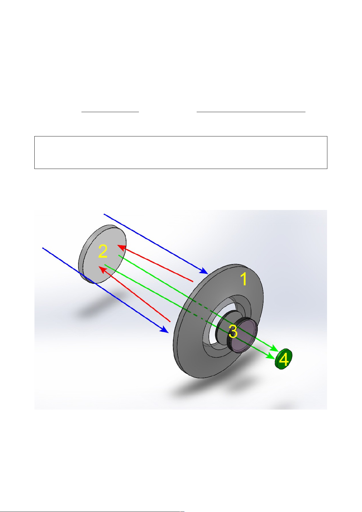
The figure above represents UltraCRC, RiDK, RiLa and RiFast telescopes. They all look very
similar, but:
UltraCRC telescopes are modified Ritchey–Chrétien, with a 2-lens corrector group near the
focal plane (but the secondary mirror is hyperbolic, like in "traditional" RCs).
4
RiDK telescopes are optimized Dall-Kirkham, with a 2-lens corrector and a spherical
secondary mirror.
RiLa and RiFast telescopes, are based on different "tuning" of the Harmer-Wynne scheme.
Like in the RiDK the secondary mirror is not hyperbolic, and this allows a bit "relaxed"
tolerance on collimation. The lens corrector group has 3 elements.
Anyway, in all such telescopes the light coming from the sky (blue arrows) is focused by the
primary, concave mirror (1 & red arrows) on to a divergent secondary mirror (2). The secondary
mirror reflects again the light through a hole in the primary mirror, where a 2 or 3 lens corrector is
located (green arrows and 3). The image forms at the focal plane (4) where a detector (or an
eyepiece) is placed. The unique shape of mirrors and lenses, and a sophisticated system of light
baffles provide a focal plane that is reflections-free, well illuminated, wide and flat. All telescopes
provide, at the focal plane, a star spot size that is much smaller than almost any CCD/CMOS pixel.
Obviously the shape of mirror/lenses and their spacing is different in each model, to achieve the
best optical performance for a given aperture and focal ratio.
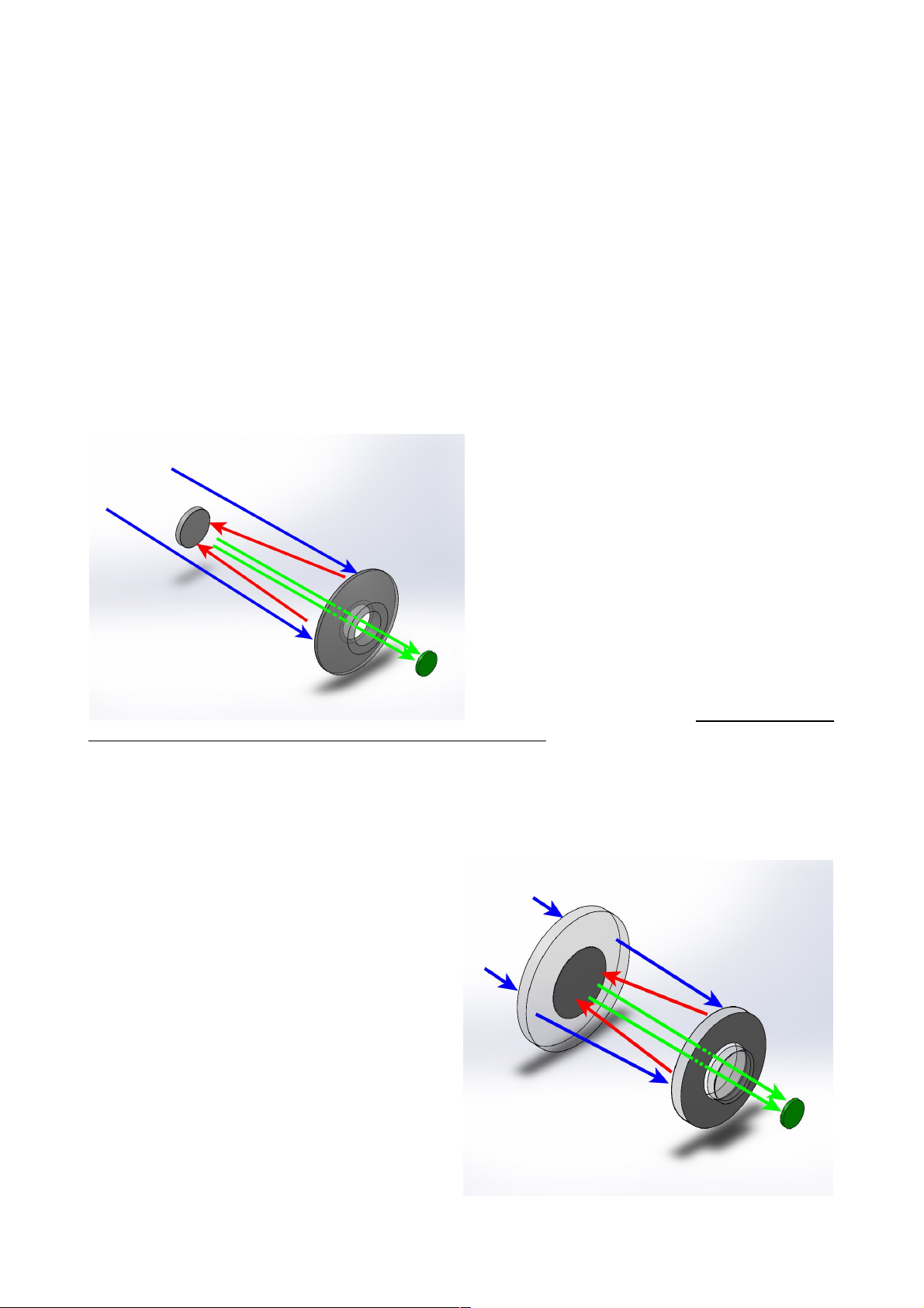
RC and RH "Veloce" telescopes are a bit different. In the RC series, a "pure" Ritchey–Chrétien
design, there is no lens group before the focal
plane and the secondary mirror is hyperbolic
(figure at left). This is in theory the "best" and
simplest solution for deep sky imaging (many
professional giant telescopes, including the
Hubble Space Telescope, are Ritchey–
Chrétien) but can't be done with low (i.e. "fast")
f/ ratios. The size of the aberration-free focal
plane is smaller than in other schemes, and
collimation is really critical.
The RH "Veloce", on the other hand, is the
most complex optical scheme used by Officina
Stellare, but it is simply the best solution for
wide field photography, and it is the only really
new scheme for telescopes to enter production in decades! You see it in the figure below. In RH
telescopes, there is a meniscus front lens that is weakly convergent, and the primary mirror is a
"Mangin" mirror (from the name of its French inventor). A Mangin mirror is a mirror that is coated
on the back surface, not on the front. The light passes through the glass, is reflected by the
coating and then passes again through the glass. For this reason, a Mangin mirror is called a
refractive-reflective optical element, and opens exciting possibilities to optical engineers. This
complex design includes also a corrector group
before the focal plane, achieving performances
impossible otherwise, with extraordinary "fast"
photographic performances over wide focal
planes. We called our RH telescopes "Veloce"
because this word, in Italian, means fast. A
curiosity about RH telescopes: since the
meniscus (frontal lens) is convergent, the
Mangin mirror is smaller than the "nominal"
diameter of the scope, while the meniscus itself
is bigger than the nominal diameter, to ensure
a good illumination over the wide field of view
of such scopes. For example, the 200 mm
model has a 220 mm meniscus and a 190 mm
primary mirror. The secondary mirror is a
separated piece of glass, or it is made coating
the middle of the meniscus, depending on
model.
5

This wide range of different schemes allows Officina Stellare to satisfy very different customers,
for very different purposes, even non-astronomical, such as satellite tracking, laser
communication, defense applications, and more.
We can customize telescopes for diameter, focal length, size of the focal
plane, spectral response, and many other parameters, to fit any need, from
the amateur astronomer to the aerospace & defense industry, to the space
agencies.
That's why we offer so many different optical designs. We do not offer
compromises to our customer. We always offer the best solution. And if
we don't have your solution on the shelf, probably we can design and
build it!
And why do our telescopes have focal planes that are much bigger than
today's sensors? Because we want you to be happy about your instrument
even 10-20 years from now, when you will use your next CCD camera, and
the one after that...
* Only the frontal lens (meniscus) of RH "Veloce" telescopes is made in Germany under Officina Stellare specifications.
6
CHAPTER 2: WHAT IS IN THE BOX
Any Officina Stellare telescope comes, at the very minimum, with a set of Hex wrenches ("Allen"
keys), documentation in electronic format on a USB key, and (excluding RH "Veloce") the
electronic "box" and cables to control mirror heaters and tube fans; but many, many options are
available, such as shutters, collimation tools, adapters for your specific optical train, environmental
sensors, advanced electronics, and more. To help you check all the equipment, a checklist like
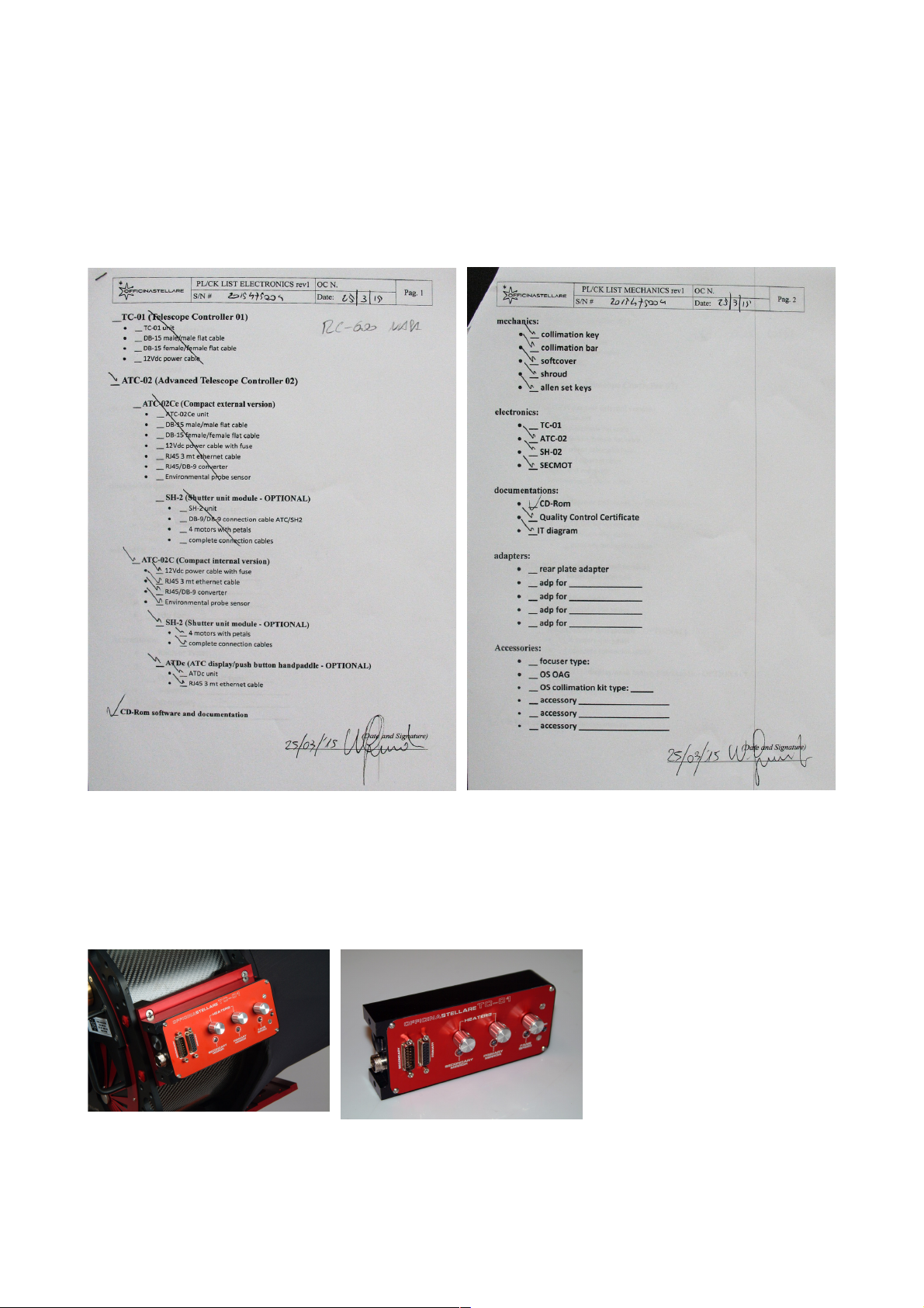
this is provided.
A two-page packing list for an Officina Stellare telescope. In this example, it is a RC-600 with
ATC-02C controller (embedded on the scope), optional primary mirror shutter, optional hand
paddle, but no adapters or accessories. Please read carefully your packing list, double check it
against your order, and identify all the parts. Should you think something is missing, or you are not
able to identify any piece, please contact Officina Stellare immediately. We will be glad to help
you. Specific manuals may be provided for some specific accessories.
In big telescopes, the electronic
panel is embedded on a side of
the tube (left photo) or in the
back of the primary mirror cell.
In smaller instruments, the
electronic may be a small,
external box. But the internal
circuit, the functionality and the
use are identical.
7

CHAPTER 3: HOW TO HANDLE THE TELESCOPE
Each Officina Stellare telescope has a very rigid and stiff structure, essential to maintain the
optical parts in the correct reciprocal position during regular use. But some part of the telescope
are quite delicate and precisely aligned. So pay great attention to "where you can grab" your
telescope to move it and to install it on your mount.
In the above photograph GREEN arrows indicate the "strong" parts of the telescope. The metallic
rings of the truss structure, dovetail plates and back handles. Any of this parts is ok to lift or handle
the scope (use at least TWO of this parts). You can also use the carbon tubes of the truss
structure, if needed (yellow arrows), if you use at the same
time also one "strong" part. Avoid to lift the scope using
the secondary mirror support, secondary mirror spider and
all light baffles (red arrows). Those parts are quite delicate
and very precisely aligned. Even if your telescope is small,
we suggest to work with another person, to lift it on the
mount.
If your telescope is heavy– and you need a crane or some
other machinery to lift it – please use a strong rope and
pass it into holes of the middle and rear rings of the truss
structure, as you see in the photo at left. This procedure
will preserve alignment and the telescope finish.
8
CHAPTER 4: ELECTRONICS CONTROLS
Excluding RH telescopes, where there are only cooling fans, your Officina Stellare telescope is
always provided with one of the following electronics packages:
TC01 – The basic model.
ATC-02 – The advanced model, that allows also to control all functions of your telescope from
a remote PC.
Both require 12Vdc. The power consumption of the electronic itself (and fans) is minimal, but
shutters and heaters may be a bit energy hungry, especially in big telescopes. Provide a 6A PSU
(Power Supply Unit) for telescopes up to 400 mm, 10A for the bigger models.
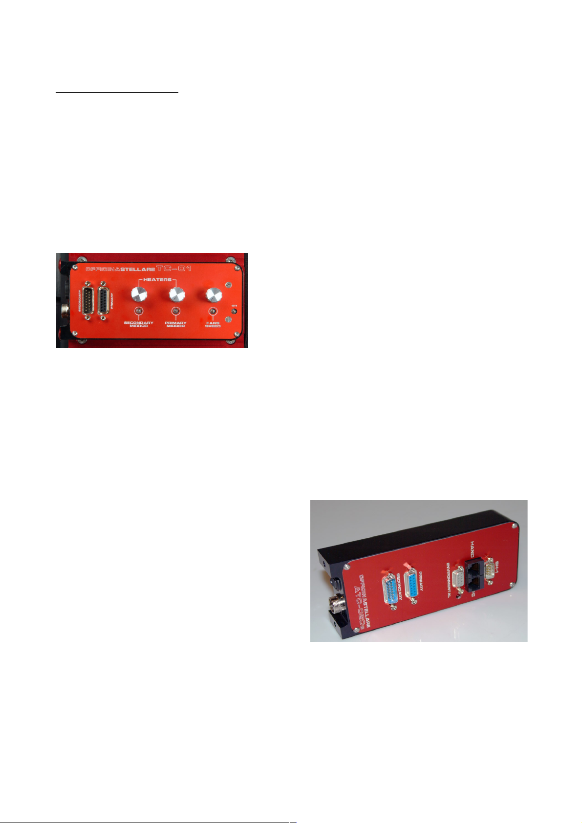
TC01 – (Telescope Control 01) –Controls only the primary and secondary mirror heaters and
cooling fans. You see it in the following photo.
On the left side you see the connectors for 12V dc
power and the on/off switch, if present. Units with no
on/off switch on/off switch are turned on and off simply
plugging in the power cable.
Some units have an internal fuse (you must open the
box to change it), while some other have the fuse on the
power cable.
On the TC-01 you also see the connectors for the flat cables that power the primary and
secondary mirror heaters. Cables have different connectors, so it is not possible to make wrong
connections. The three knobs control the power to the heaters and the fans speed. As a general
rule, do not use the heaters, unless you see some mist on the mirrors. If you turn on the heaters,
try to keep them at the lowest temperature that avoid the mist. The intensity of the LED is
proportional to the power of each heater. Regarding the fans, run them at maximum until the
seeing stabilizes. After that point run them at half or one third power, or even turn them off until the
end of the night. The use of cooling fans is proportional to the temperature change that the
telescope suffers from day to night. The higher the temperature change, the longer you have to
run fans to reach equilibrium.
ATC-02 – (Advanced Telescope Controller 02) –
The ATC02 is provided with a serial cable to
connect is to a Windows computer, physically
located in the vicinity of the telescope.
This PC, usually, will also manage a CCD camera,
the mount, the dome, autoguide, and so on, and in
case of a remote installation, it is remotely
controlled via a dedicated software, like Remote
Desktop, VNC or others.
On the ATC-02 you see the power connector,
on/off switch and mirrors heaters connectors, that are identical to those of the TC-01, and works
the same ways. The other connectors present are:
Environmental: to connect a humidity / temperature sensor, embedded in the telescope
body. Since those parameter are enough to compute the dew temperature, this sensor
allows the telescope to keep its mirrors just "warm enough" to avoid condensation
automatically, following the changes of the conditions during the night.
Hand: connector for the optional hand pad (keyboard).
9
PC: serial connection to the PC (cable provided). USB-to-serial converters works fine.
SH-1: connection to the (optional) primary mirror shutters.
The ATC-02 also controls the optional electric motor that moves the secondary mirror (along its
optical axis). The electrical connections for this motor, if installed, run on the same cable used by
the secondary mirror heater. Move the secondary mirror will change the BFL (Back Focus Length,
i.e. the distance between the back plate of the telescope and the focal plane). This system is used
to focus the scope when a quick focus is essential, like is some non astronomical applications, or
when the equipment at the prime focus is too heavy for a traditional focuser, or you need some
extra BFL because of "thick" equipment at the focal plane, such as a filter wheel, a big CCD
camera, off-axis guider, and so on. The telescope "knows" the best position for the secondary
mirror – the design distance, where the optical performance are at best – and an internal sensor
permits the mirror to find this optimal position. But the movable secondary mirror is the only choice
in particular situations. You sacrifice a bit the optical performance simply to reach focus.
The ATC-02 has been designed with the computer control in mind, for a wholly remote-controlled
telescope. The hand pad is clearly a "second chance" solution. You can connect your ATC-02 to a
PC and to a hand pad at the same time. The ATC-02 will accept commands from both sources.
The latest command has priority.
4.1) Use of the ATC-02 with the computer
To control the ATC-02 from the computer, you will use our ATC-Remote software, provided with
your ATC-02. The software is quite simple, its interface is clearly divided in two. On the left you
have two tabs ("Quick controls" and "Temperature control") where you can send commands to the
telescope. On the right other two tabs ("General information" and "Data log") informs you about
the current and "historical" status of your scope. Let's look each tab in detail.
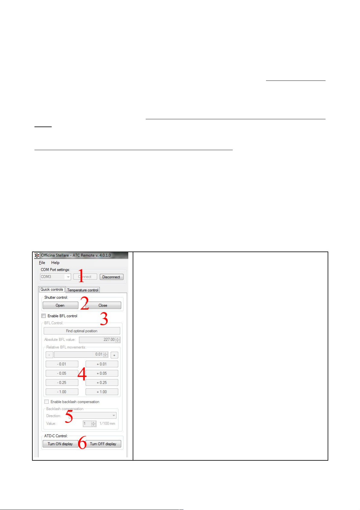
"Quick controls" tab
From this tab you can:
1) Choose the serial port where your telescope is connected,
and establish or terminate the connection. USB-to-serial
converters can be used. In this case check with Windows
the number of this "virtual" COM port.
2) Open/close the shutters, if installed
3) Enable the BFL control. The big "Find optimal position"
button brings the mirror to the "optimal" position, set during
manufacturing (best optical performance).
4) Mirror movements. You can set an absolute position, or
move the mirror by ±1, ±0.25, ±0.05 or ±0.01 mm per step
5) You can enable a backlash compensation for the mirror
movements. Backlash compensate the minimum "dead time"
you see when you change the direction of motion in any
mechanical system, like your secondary mirror. Use this
parameter only if directed by Officina Stellare support.
Usually you simply look at the image captured by the scope
to change secondary mirror position, but for particular
situations a backslash control is useful.
6) With this buttons you can turn on/off the hand pad, if
installed. This is to avoid the local control of the telescope (if
you are using it remotely) or simply to reduce the illumination
inside the dome.
10
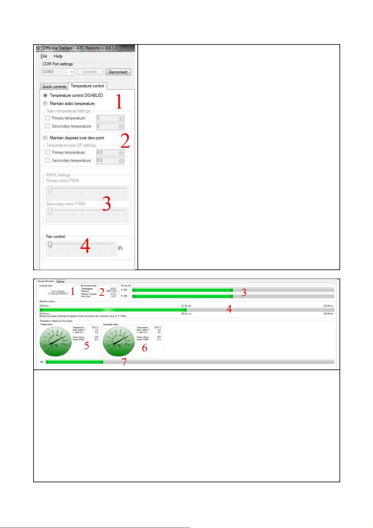
"Temperature control" tab
From this tab you can:
1) Leave the temperature control OFF, or keep the mirrors at a
constant temperature (only ABOVE ambient, of course).
2) Keep the mirrors a given temperature above the dew point
temperature (calculated by the internal sensor).
3) Set the Pulse Width Modulation of each heater. PWM is
something like a limit to the "maximum power available". If
you heat the mirror too quickly, the mirror may warp a bit,
(temporarily!) and produce bad images. To warm the mirror
slowly, set the PWM to no more than 50%. The software will
warn you if are using a "high power" set.
4) Set the fans speed. Run them at maximum until the seeing
stabilizes. After that point run them at half or one third
power, or even turn them off until the end of the night. The
use of cooling fans is proportional to the temperature change
that the telescope suffers from day to night. The higher the
temperature change, the longer you have to run fans to
reach equilibrium.
"General information" tab
From this tab you read:
1) Owner data, as written in the memory of the scope when it was produced.
2) Environmental data (temperature, pressure, relative humidity and dew point), measured (or
calculated) by the telescope sensors.
3) Tilt and roll of the scope, as read by gravity-referred sensors internal to the scope. This data is
useful to control if the telescope has reached the "park" position or is moving at all. In other
word, this is a way to control if the telescope mount is working properly. This sensors are not
sensitive enough to point the telescope, but will be useful during the setup and use of a remote
controlled telescope. By the way, we suggest to install webcam, possibly with IR capabilities, in
the dome, to take a look to your telescope during operation!
11
4) Back focus position. This data is meaningful only if the secondary mirror motor is installed. The
minimum, optimal and maximum position are real measurements, in mm.
5) Real temperature, set temperature and heater status for the primary mirror
6) As above, for the secondary mirror
7) Fan speed. Parameter 5, 6 and 7 are set in the "Temperature control" tab.
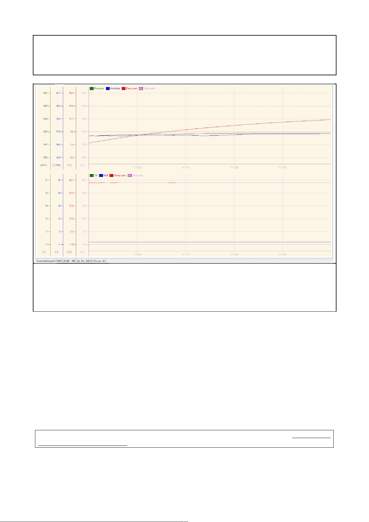
"Data Log" tab
Simply shows as two multiple Y-scale graphs a log of all the above parameters. On the bottom you
read the COM port, telescope model, software version, telescope firmware version.
4.2) Use of the ATC-02 with the hand pad
The hand pad is connected to the ATC-02 via a male-male RJ-45 cable. The cable fits also the
"PC" port on the ATC-02, but there is no risk of damage if you make a mistake. If you plug the
hand pad cable in the "PC" connector or vice-versa, the hand pad (or the PC connection) will
simply not work. Use the correct connector!
As soon as you power up the ATC-02, the hand pad will briefly show the firmware revision. This
information will be useful if you contact Officina Stellare customer service. After the firmware
revision, you will see briefly the serial number, telescope model and owner information, written in
the memory of the scope following your order. Finally, the hand pad will start to "cycle" between
five different screens.
The first three lines of the display will continue to cycle between the five "screens". The user will
interact only with the last line.
12
 Loading...