

Page 1
SPRINT 5000
BOOKLETMAKER
OPERATION MANUAL
Page 2

Sprint5000HCS-USA.doc3.doc Page 1 01/05/2002
CONTENTS
1. Introduction. 2
2. Specification. 2
3. Initial setting up. 3
4. Operation. 4
4.1 Loading staples. 5
4.2 Staple out system. 7
4.3 Staple jam. 7
4.4 Paper width settings. 8
4.5 Stapling / folding positions. 9
4.6 Changing stapling head positions. 11
5. Booklet making. 12
6. Corner and edge stapling. 14
7. Counter. 17
8. Replacing stapling heads. 17
9. Aligning of stapling heads. 17
10. Problem solving. 18
Appendix A: Parts lists and drawings.
MBM Corporation
Michael Business Machines
3134 Industry Drive
North Charleston
South Carolina 29418
Customer Service - Tel: (800) 223 2508
Fax: (803) 552 2974
Parts & Service - Tel: (800) 223 2508
Fax: (803) 760 3814
Page 3

Sprint5000HCS-USA.doc3.doc Page 2 01/05/2002
1 INTRODUCTION
• The Sprint 5000 Bookletmaker centre staples and folds to make booklets between 4” x 5½“
and 8½“ x 11” with up to 80 pages. On each cycle of the machine one set of sheets is stapled
and the preceding set is folded and stacked on the conveyor belt.
• It is also possible to edge and corner staple up to 20 sheets.
• The machine can either be hand fed or placed on-line to one of the various desktop vertical
collators, using a KAS conveyor/ jogger link. A stand is also supplied to carry the collator so
that it is the correct height for feeding into the Bookletmaker.
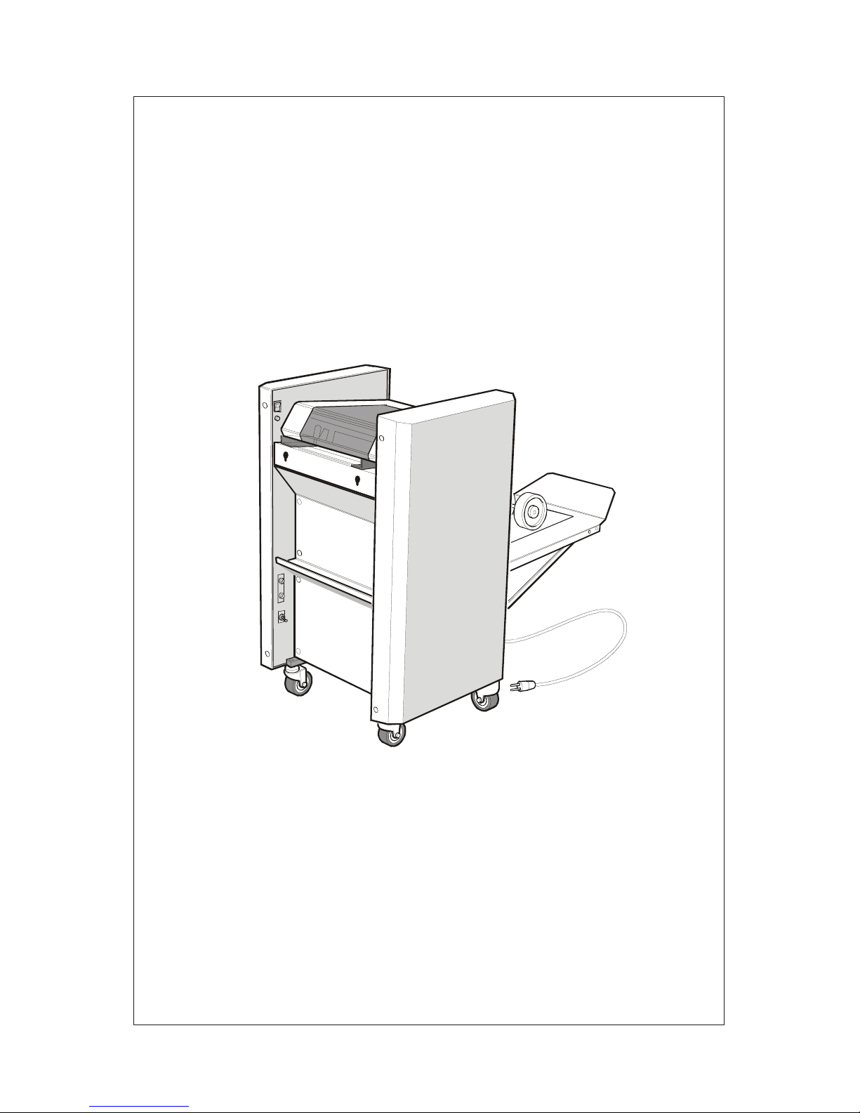
• The Sprint 5000 is a floor standing machine fitted with sturdy castors and an integral conveyor
which can be folded up in order to occupy minimal floor space when not in use.
• This model has five stapling positions t o which the stapling heads can be moved according to
the size of paper. The right hand outside position is for corner stapling.
• A Staple Out Detector is fitted to each of the stapling heads, and the Bookletmaker will stop
when the stapling head runs out of staples.
2 SPECIFICATION
INPUT CAPACITY: Booklets 20 sheets of 20 lb bond
Pads 20 sheets of 20 lb bond
SHEET SIZES: Booklets 5½“ x 8” to 11½“ x 17½“.
Pads 8½” x 11½“
STAPLES 5000 staple cartridge
DIMENSIONS Width 23”
Height 36”
L e ng th 20” (Conveyor stored).
L e ng th 46” (Conveyor in use).
WEIGHT 205 lbs.
POWER 115v 60Hz
Consumption approx. 180 Watts
Fuse: 10 amp 115v.
Page 4
Sprint5000HCS-USA.doc3.doc Page 3 01/05/2002
3. INITIAL SETTING UP
1. Remove the bolts holding the machine to the pallet.
2. Castors are already fitted to the machine, lift from the pallet on to an even surface.
3. Remove packing from stapling section and from under fold stop beneath the conveyor.
4. Lower output conveyor, allowing the slotted ends on the support bars (part no. 6.06) to locate
on the protruding bolts provided. These bolts are located at the base of the machine.
5. When making books, one need only fit the conveyor wheels (part no.6.13) and make sure that
the divert plate (part no. 3.71) shown in figure 2 is pushed forward.
Figure 1 - Conveyor setup.
6. Insert the conveyor end stop (part no. 6.11) at the far end of the conveyor, making sure it does
not infringe the belt. It is held in position by a flat mag net.
7. Position the machine near to a suitable socket outlet and ensure outlet is not covered and is
easily accessible.
8. Check that the power supply is of the correct voltage for the machine. Once connected, the
machine is ready for use.
Page 5
Sprint5000HCS-USA.doc3.doc Page 4 01/05/2002
4. OPERATION
44
40
38
36
34
32
28
26
24
22
20
18
16
14
12
10
A4
A5
A3
8714
5
4
3
2
1
9
10
4
11
12
13
Figure 2 - Control layout
1 Fold stop lock thumbscrew 8 Staple position fine adjustment screw
2 Stapling head position arm 9 On / off button
3 Edg e staple stop thumbscrew 10 Staple delay knob
4 Side g uide clamping thumbscrew 11 Staple/fold stop indicator
5 Staple low indica tor / re set 12 Fold stop tilt adjustment thumbscrew
6 13 Staple & fold stops adjustment wheel
7 Anvil 14 Counter
Page 6

Sprint5000HCS-USA.doc3.doc Page 5 01/05/2002
4.1 Loading Staples :
1. Only those staples sold or recommended by your supplier should be used in the Sprint 5000
Bookletmaker. Use of non recommended staples may damage the stapling heads and they are
not covered by any warranty.
2. Raise the top cover.
3. Raise metal locking bar upwards and remove spent cartridge. Ensure the bar is in the
uppermost position otherwise the cartridge may not load properly.
4. Make sure that st aples do not protrude past the staple tear line. If necessary the staples are
easily torn off at the tear line by tearing downward.
5. Cartridge should be placed flat on the slide in the body of the stapler and pushed firmly
forward. Do not allow the cartridge to move backwards once inserted into the stapler. If this
occurs remove cartridge from stapler and tear off staples at tear line again before re-inserting.
6. To keep the cartridge in place push metal locking bar down until it snaps into the grove on the
back of the cartridge.
7. Press staple out reset button, lower top cover.
8. The staples do not immediately feed through to the plunger and therefore the machine will not
staple during the first three or four cycles after loading. Where this is a problem, refer t o 9 and
10 below.
9. Turn off staple out detector (select the centre position on the three-way toggle switch, see 4.2)
10. To avoid books being processed without staples, cycle the machine by placing scrap paper
beneath the heads. Repeat this until staples appea r in the pape r.
11. Turn on staple out detector and continue producing books.
Page 7
Sprint5000HCS-USA.doc3.doc Page 6 01/05/2002
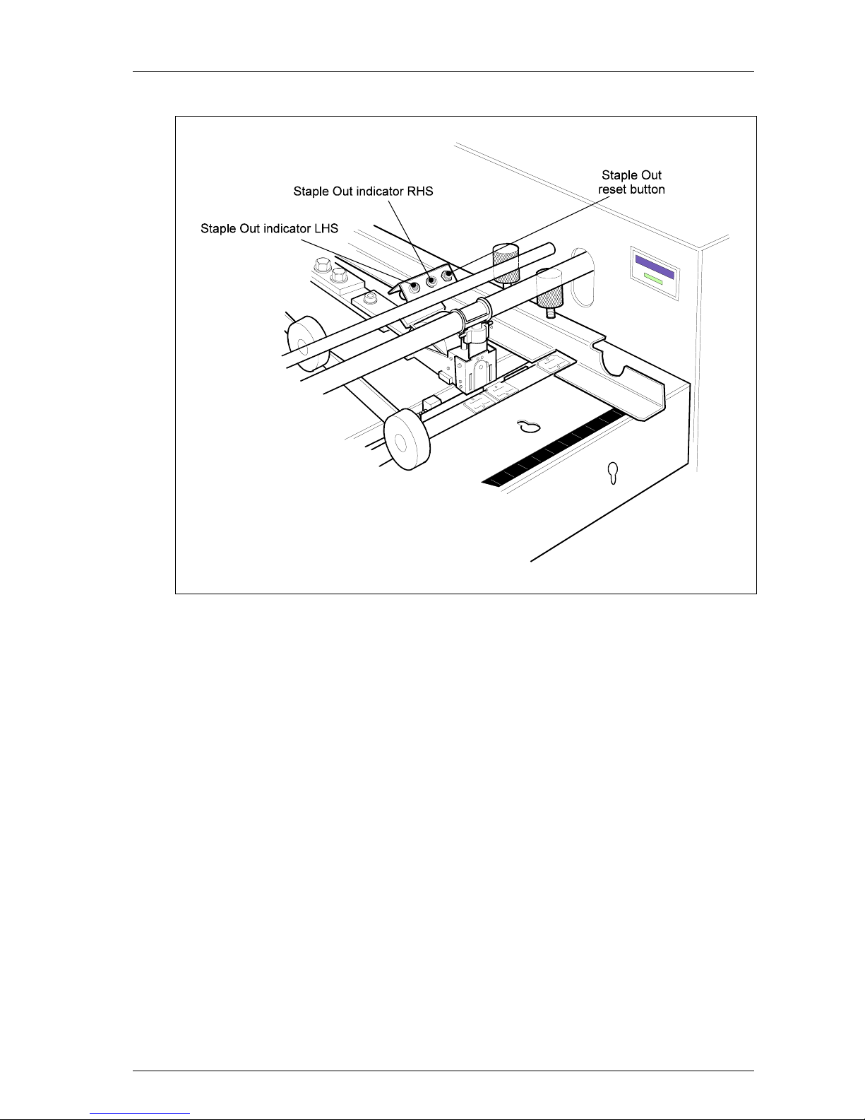
Figure 3 - Staple Out reset/indicators.
Page 8

Sprint5000HCS-USA.doc3.doc Page 7 01/05/2002
4.2 Staple Out System :
This is switched on and off using a three-way toggle switch located on the inside left-hand side wall
underneath the shelf. Select the switch position as follows.
1. With the toggle switch is in the central position the staple out detectors on both heads are off.
2. With the toggle switch pushed downwards both staple detectors are on.
3. When the toggle switch is pushed to it’s furthest position upwards only the staple out detector
on the right-hand head is on (corner stapling).
The above is displayed on the legend plate around the switch (shown in figure 8.).
When the stapling head runs out of staples the red light pertaining to that head will illuminate and
the booklet maker will not cycle. The last set will not be stapled and should be removed from the
fold section. It can be reprocessed once the staple head(s) has been refilled.
4.3 Staple Jam :
To clear jammed staples from heads, it is best to remove the cartridge, clear any damaged staples
from stapling head and anvil, and replace the cartridge as described in 4.1.
WARNING - One may clear the jammed staples by operating the p lunger manually. In this
instance take care not to put fingers under front-most portion of stapling head, so avoiding
injury to fingers from staples being ejected from the head.
Page 9
Sprint5000HCS-USA.doc3.doc Page 8 01/05/2002
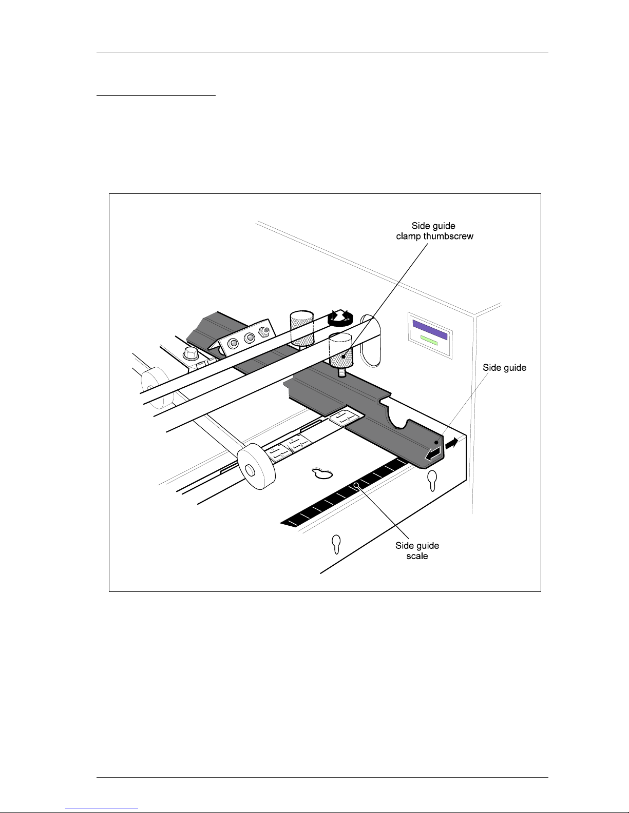
4.4 Paper Width Settings:
1. Both sides guides should be adjusted for a given size of paper. Loosen the thumbscrews and
move the side guides until their outside edges are level with the marking on the scale
corresponding to the width of the paper, and then re-tighten the thumbscrews so that the guides
are held in place.
Figure 4 - Side guides.
2. Note that the marked settings are meant to be wider than the paper, to allow for side jog. Both
guides move inwards on each cycle to the correct width to ensure that the sheets are aligned
before stapling occurs.
3. When corner and edge stapling 8½“ x 11” paper, feeding landscape, the guides are set to the
11“ x 17” markings.
Page 10

Sprint5000HCS-USA.doc3.doc Page 9 01/05/2002
4.5 Stapling / Folding Positions :
1. The Stapling and the Folding positions are adjusted as one. Loosen fold stop lock
thumbscrew, figure 5.
2. Turn the fold stop adjustment wheel until the staple stop aligns with the appropriate ca libration
on the scale, for the size of paper being used.
Figure 5 - Fold stop
3. Re-tighten fold stop lock thumbscrew when the stop has been correctly positioned.
Page 11
Sprint5000HCS-USA.doc3.doc Page 10 01/05/2002
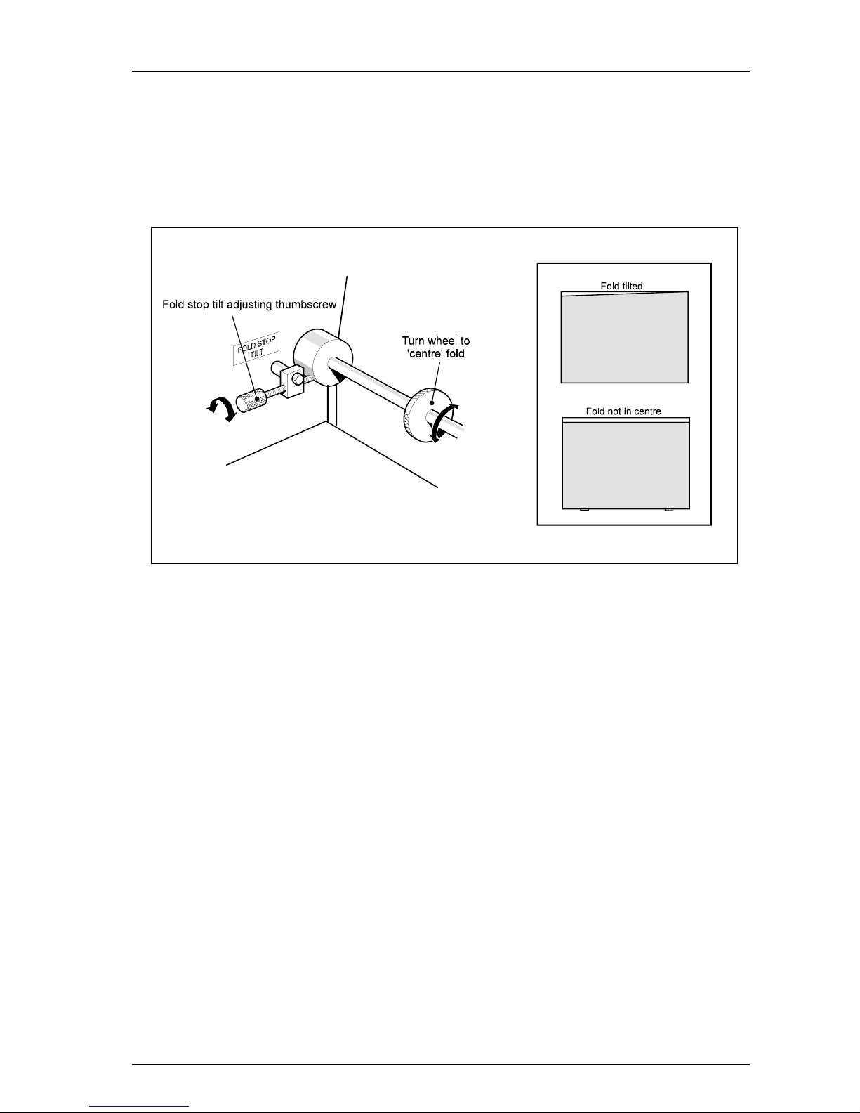
4. If fold line is not perpendicular to booklet edges, this can be corrected by adjusting the fold
stop tilt thumbscrew, figure 6, on the left-hand side of the fold stop adjusting shaft. Loosen the
locking nut and turn the thumbscrew clockwise to raise the left-hand end of the fold stop, or
anti-clockwise to lower. Tighten locking nut.
Figure 6 - Fold stop tilt.
Page 12
Sprint5000HCS-USA.doc3.doc Page 11 01/05/2002
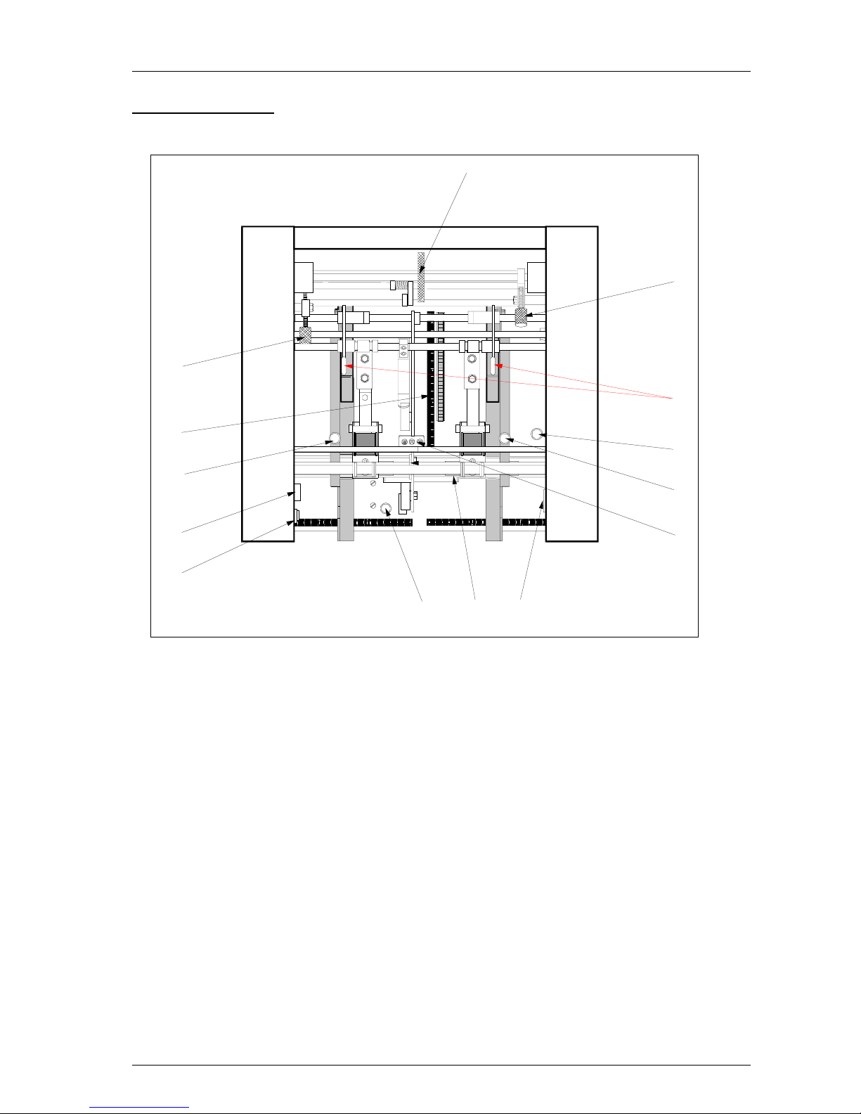
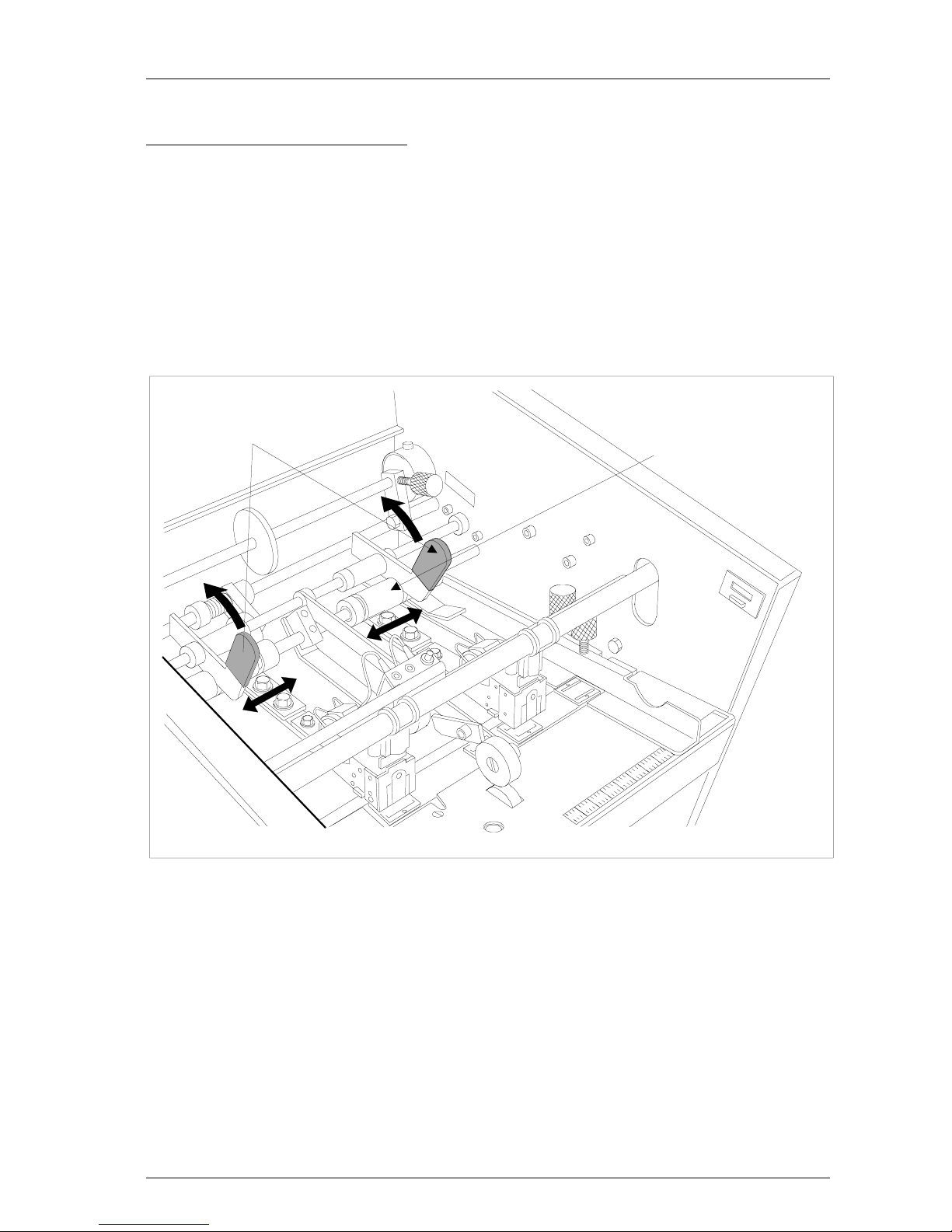
4.6 Changing stapling head positions.
1. To move the stapling heads to the alternative positions, lift the stapling head position arm,
figure 7, then slide the entire stapling unit to the new position.
2. When moving the stapling head, hold the slide bracket at the retaining plate end, and move to
new position.
3. Drop the position arm into the new slot on slide bracket, which will align the stapling head in
the new position.
Staple head position a r ms
Slide bracket
Figure 7 - Stapling head adjustment and anvil positions
4. Positions are provided for the various sized books between 4” x 5½“ and 8½“ x 11” paper,
with an additional position on the far right for c orne r stap ling 8½“ x 11”.
Page 13

Sprint5000HCS-USA.doc3.doc Page 12 01/05/2002
5. BOOKLET MAKING.
1. The machine will not operate with the top safety cover in the raised position. After closing the
top safety cover it is necessary to press the circuit reset button, located in the left hand inside
side wall. This is an added safety feature and the machine will not cycle until the button is
pressed.
Figure 8 - Operating controls
2. When the machine is switched on the motor will not start until the first set of paper is placed in
the machine. If it is left running and not used for a period of more than three minutes the
motor will automatically switch off. The motor will re-start when paper is placed in the
machine.
3. The stapling / folding operation is started when sensors detect the paper in the machine. The
time between the paper entering the machine and the stapling action can be varied. This is
achieved by turning the Stapling Delay Control shown in figure 8 clockwise for more time and
anti-clockwise for less. When first using the machine, give the Stapling Delay Control a
quarter turn clockwise. This will give time for the operator to settle the paper between the
guides before the machine cycles.
Page 14

Sprint5000HCS-USA.doc3.doc Page 13 01/05/2002
Page 15

Sprint5000HCS-USA.doc3.doc Page 14 01/05/2002
4. When paper is placed in the machine it breaks the light beam between the photocell emitter
(part no. 2.83) and the photocell receiver (part no. 2.71). On the interruption of the beam the
time set by the timer expires a nd the ma chine will oper ate for one c ycle.
5. If the stapled set fails to drop into the folding position the guides may be set too closely and
must be set slightly wider. The first set placed in the machine will not fold and exit to the
conveyor until the second set is being stapled. To release the last set from the machine, hold a
scrap of paper under the stapling heads for one cycle and then remove it.
6. The conveyor wheels shown in figure 11 should be adjusted so that the wheels are just over a
book’s distance from the fold rollers. Too close and they will interfere with subsequent
booklets coming out of the fold rollers. If the wheels are too far away the booklets will have
the tendency to insert themselves inside previously ejected booklets.
7. Staple Position Fine Adjustment. If, after correctly setting the fold stop adjustment wheel, it is
found that the staples are not exactly on the fold line, this can be corrected by turning the
staple position fine adjustment screw, figure 9.
Figure 9 - Staple position fine adjustment
Looking at the finished booklets laying on the stacker table after ejection from the fold
rollers, if the staples are visible above the fold, turn adjusting screw anti-clockwise. If the
staples are below the fold, turn adjusting scr ew c lockwise.
Page 16

Sprint5000HCS-USA.doc3.doc Page 15 01/05/2002
6. CORNER AND EDGE STAPLING
Refer to figure 10.
1. Open the top perspex cover. Move the paper width guides to the position where they will side
jog the set of paper without impeding its path through the machine. For 8½“ x 11” paper, set
the guides to the 11“ x 17” markings.
2. For edge stapling, select the desired pair of anvil positions. When corner stapling move the
right hand stapling head to the furthest right position, and remove the staple cartridge from the
left hand stapling head. Then move the left- hand stapling head and lock it down in position
where it is not over an anvil. Alternatively one could also remove the left-hand stapling head
as described in section 8 concerning replacing stapling heads.
3. Turn the corner/edge stop adjust thumbscrew, located in the second paper table shown in
figure 10 to the right of the right-hand paper width guide, anti-clockwise. The stop will rise
just behind the Anvil bar.
Figure 10 - Corner/Edg e s t ops.
Page 17

Sprint5000HCS-USA.doc3.doc Page 16 01/05/2002
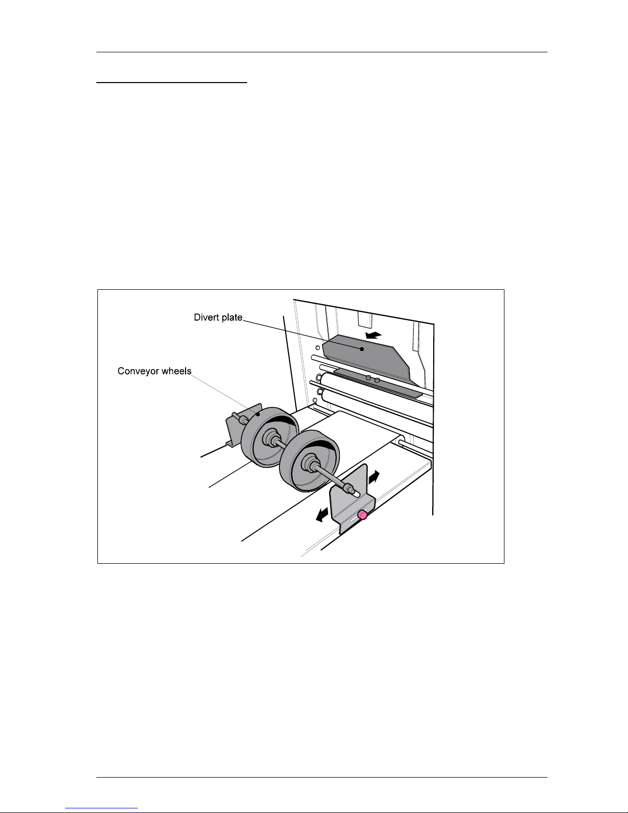
4. Push the divert plate (part no. 3.71) back against the Top front plate (part no. 3.42), figure 11.
This will divert the set of paper away from the folding section and out of the machine.
Figure 11 - Conv eyor setup 1.
5. Fit the deflector plate, by fitting its hook over the tie bar, so that it rests on the outfeed
conveyor.
6. Move the conveyor wheel support brackets which are held in place by thumbscrews, so that
the edge nearest the main body of the machine is approximately 6” from the start of the
conveyor. Figure 12 shows which way round they are fitted.
Page 18

Sprint5000HCS-USA.doc3.doc Page 17 01/05/2002
Figure 12 - Conv e yor setup 2.
7. Place the conveyor wheel spindle (part no. 6.17) into the slots provided in the conveyor wheel
support brackets.
8. As a set exits the machine down the Exit plate it should first come to a stop so that
approximately 1” of the tailing edge is still resting on the raised upper portion of the Exit plate.
During the next cycle that set will drop down to the next level avoiding the following set
which will lay on top.
9. Ensure that the appropriate stapling head(s) is loaded, and the staple cartridge firmly pushed
home. If staple out system is in use, press the staple out reset button. Close Perspex cover.
10. When hand feeding, insert the set to be stapled into the machine, underneath the stapling
heads, until the leading edge touches the paper stops. The machine will cycle, when the
sensors detect the paper, taking the set through the machine.
11. When on-line to a desk top collator, running 8½“ x 11” paper, using a KAS conveyor/ jogger
the link bracket should be fitted using the 11“ x 17” bookletmaking slot. The back jogger
should also be in the 11“ x 17” position.
Page 19

Sprint5000HCS-USA.doc3.doc Page 18 01/05/2002
7. COUNTER
The counter can be reset to '0000' by pressing the rectang ular black button below the number
window.
8. REPLACING STAPLING HEADS
Should it become necessary to remove either or both of the stapling heads follow the procedure
below.
1. Pull the left-hand side of the spring clip so that the eye clears the pin and swivel the spring clip
anti-clockwise around the actuating bar. This should remove the hook on the right-hand side of
the clip from the other end of the pin.
2. Unplug the electrical lead from the bracket containing the reset button and lights.
3. Loosen the small ( M6) bolt in the stapling he ad reta ining plate suff icien tly so that the retaining
plate can be lifted and pushed aside revealing the trough in which the bar at the back of the
stapling head is located.
4. Take the bar from the trough and having removed the head completely replace the retaining
plate in it’s original position and tighten the bolt.
5. To re-fit a new head place the bar at the back of the stapling head into the trough, position the
retaining plate over the top and tighten the bolt and replace the spring clip. Replace electrical
lead.
9. ALIGNING OF STAPLING HEADS
Replacement stapling heads may be fitted to the Bookletmaker. If th e repl acement head i s giv ing a
bad staple, then remove power from the machine and re-align the head as below.
1. Remove cassette of staples from stapler.
2. Loosen the hex screws holding part no. 2.105
3. Place the adjustment guide between stapler and anvil.
Align and insert the raised lugs of the guide into the underside of the stapler where the
staple exits, making sure the metal locating pip is to the front. When inserted replace the
cassette of staples.
Page 20

Sprint5000HCS-USA.doc3.doc Page 19 01/05/2002
4. Locate pip on adjustment guide into small hole at front of anvil and then retighten hex
screws. The stapling head should now be in a position to carry on stapling after removing
adjustment guide.
Page 21

Sprint5000HCS-USA.doc3.doc Page 20 01/05/2002
10. PROBLEM SOLVING.
PROBLEM POSSIBLE CAUSES REMEDY
Motor will not start Blown Fuse Switch off and unplug machine.
Check and replace fuses as
necessary
Machine will not start
when paper is inserted
Powerful light source from
above
Shield safety cover from light or
move machine
Machine will not cycle Machine in jam mode Remove paper from machine in
stapling section to allow photo-cell
to reset
Stapling head jammed Incorrectly fitted staple
cartridge
Switch off machine, lift safety
cover, remove cartridge, clear
jammed staples and replace.
Repeated jamming of
stapling head.
Miss aligned head with anvil Check alignment of stapling head
and anvil.
Staple legs breaking. Miss aligned head with anvil Check alignment of stapling head
and anvil.
One staple not on fold
line
Fold stop out of line Adjust tilt screw
Book does not travel
through machine after
stapling
Side guides too tight Open right hand side guide
Pinching around staples Residue being left on rollers Clean rollers
Page 22

Sprint5000HCS-USA.doc3.doc Page 21 01/05/2002
Spare parts drawings
for the
Sprint 5000 Bookletmaker
Appendix A
C5003-FC 4.97
Page 23

RHS
1
2
3
4
10
11 12
1. Panels
LHS
C5000-1a 5.97
9
8
5
7
6
2
4
0
V
3
A
14
15
Page 24

kf_5002.xls 01/05/2002
5000HCS/ Part Quantity
1.00 PANELS
1.01 Side Cover 1
1.02 Bottom Front Plate 1
1.03 Top Front Plate 1
1.04 Counter (not in view). State 240vAC or 24vDC 1
1.05 Fuse Holder 2
1.06 Fuse 2
1.07 Switch - Staple count 1
1.08 Staple delay knob 1
1.09 Reset Switch 1
1.10 Power Switch 1
1.11 Side Cover 1
1.12 Perspex Cover 1
1.13
1.14 Motorised Interface Unit socket (24v DC output) 1
1.15 240v/110v AC output socket 1
1.16 Trimmer On-line socket 1
1.17 Collator On-line socket 1
Please quote machine model and serial number, with part number, on order.
Page 25

16
47
46
1
2
109,107
6
7
8
9
10
11
12
14
88
18
2. Staple section
LHS
RHS
108
19
20
93
26
28
29
30
31
32
33
34
134
36
37
35
39
40414243
50
51
54
55
48
57
61
62
58
60
65
63
68
69
104
105
70
71
135
77
78
131
80
81 82
83
138
133
85 87
56
98
101
103
99
100
102
94
95
96
91
13
24
90
17
89
64
122,67
59
132
C5002-2c cdr 8.99
110
111112113114115116117118119120121
136
137
140
139
86
Page 26

kf_5002.xls 01/05/2002
5000HCS/ Part Quantity
2.00 STAPLE SECTION
2.01 Stapling head actuator Bar 1
2.02 Top Takeaway Wheel - corner stapler 1
2.03
2.04
2.05
2.06 Corner/Edge Stop adjust thumbscrew 1
2.07 Side Guide RHS 1
2.08 Scale RHS 1
2.09 Paper Table 1
2.10 Scale LHS 1
2.11 Bearing Housing 1
2.12 Side Jog Shaft RHS 1
2.13 Bottom Takeaway Wheel - corner sta. 1
2.14 Bearing Block 2
2.15
2.16 Timing Pulley 1
2.17 Collar 1
2.18 Shaft 1
2.19 Cup Bearing 1
2.20 Front Shaft for Paper Stop Assembly 1
2.21
2.22
2.23
2.24 Paper Stop Frame 1
2.25 Fine Adjustment Plate 1
2.26 Timing Pulley 1
2.27 Paper Stop Pivot Block 1
2.28 Angle 1
2.29 Spindle 1
2.30 Collar 1
2.31 Corner stop pivot arm 1
2.32 Corner stop mount 1
2.33 Collar 2
2.34 Spindle 1
2.35 Edge/corner stapling stop 1
2.36 Link Arm 1
2.37 Return Spring 1
2.38
2.39 Stapling stop sleeve 1
2.40 Collar 1
2.41 Cup Bearing 1
2.42 Timing Belt - Takeaway drive 1
2.43 Stapling Position Stop Belt 1
2.44
2.45
2.46 Side Jog Spring 1
2.47 Collar 1
2.48 Support Blocks 2
2.49
2.50 Collar 1
2.51 Bearing Housing 1
2.52 Washer 1
2.53 Spacer 1
2.54 Side Jog Shaft LHS 1
2.55 Bearing Housing 1
2.56 Collar 1
2.57 Bottom Takeaway Shaft 1
Please quote machine model and serial number, with part number, on order.
Page 27

kf_5002.xls 01/05/2002
5000HCS/ Part Quantity
2.58 Collar 1
2.59 Center Bearing Block 1
2.60 Bottom Takeaway Wheel 1
2.61 Side Guide Extension LHS 1
2.62 Side Guide LHS 1
2.63 Paper Deflector LHS 1
2.64 Second Paper Table 1
2.65 Side Guide clamping thumbscrew 2
2.66 Anvil 2
2.67 Anvil Bar 1
2.68 Staple Stop Scale 1
2.69 Side Guide Extension RHS (not shown) 1
2.70 Paper Deflector RHS 1
2.71 Photocell Receiver 1
2.72
2.73
2.74
2.75
2.76 Stapling head locking lever 2
2.77 Bearing Housing 1
2.78 Collar 2
2.79
2.80 Pivot Shaft 1
2.81 Top Takeaway Wheel Lift Arm 1
2.82 Top Takeaway Wheel 1
2.83 Photocell Emitter 1
2.84
2.85 Staple Out Light 2
2.86 Staple Out reset button 1
2.87 Staple Out socket for interface lead (2.107) 2
2.88 Staple centring adjustment screw block 1
2.89 Staple centring adjustment screw 1
2.90 Collar 2
2.91 Control wheel 1
2.92
2.93 Belt support plate 1
2.94 Spacer - short 3
2.95 Spacer - long 1
2.96 Clamping bolt 3
2.97
2.98 Bottom plate - runner assembly 1
2.99 Top plate - runner assembly 1
2.100 Slide plate - LHS 1
2.101 Spacer - medium 2
2.102 Slide plate - RHS 1
2.103 Staple stop plate 1
2.104 Staple head retaining plate 2
2.105 Staple head capivating plate 2
2.106 2
2.107 Staple head interface lead 2
2.108 Staple cartridge 2
2.109 Staple head 2
2.110 Staple head return spring clip 2
2.111 Bottom Stop Bolt 1
2.112 Rubber Stop 1
2.113 Cam Lever 1
2.114 Clinch Activator Plate 1
2.115 Shaft 1
2.116 Clinch activator Arms 2
Please quote machine model and serial number, with part number, on order.
Page 28

kf_5002.xls 01/05/2002
5000HCS/ Part Quantity
2.117 Block 2
2.118 Collar 2
2.119 Cup Bearing 2
2.120 Clinchers 4
2.121 Clinch Spacer Plate 2
2.122 Anvil Bar for Clinchers (replaces 2.67) 1
2.130
2.131 Centre guide (replaces 2.79) 1
2.132 Stapling head universal bar (replaces 2.74) 1
2.133 Slide bracket (replaces 2.106) - LHS 1
2.134 Centre guide mounting block 1
2.135 Slide bracket - LHS 1
2.136 Staple head position arm - RHS 1
2.137 Staple head position arm - LHS 1
2.138 Protective rubber 2
2.139 Carrier tube for emmitter (replaces 2.84) 1
2.140 Smoother plate 1
2.141
2.142
Please quote machine model and serial number, with part number, on order.
Page 29

1
2
3
4
6
9
40
41
42
44
45
46
5152
535455
56
57
59
61
62
63
64
65
69
71
75
76
77
78
73
72
79
80
81
82
83
84
85
3. Fold section
REARRHS
C
50
0
23a
1
1
.
98
47
48, 49
66
86
87, 88
89
7
8
11
50
74
43
FRONT
60
25
26
27
29
30
37
31
32
33
34
38
35
36
LHS
39
14
12
15
18
28
23
24
16 17 191320 21
22
91
Page 30

kf_5002.xls 01/05/2002
5000HCS/ Part Quantity
3.00 FOLD SECTION
3.01 Staple & Fold stops adjust wheel 1
3.02 Bearing Housing 1
3.03 Fold Stop Tape Wheel 1
3.04 Fold Stop Tilt Thumbscrew 1
3.05
3.06 Spacer 1
3.07 Fold Stop Tilt Block 1
3.08 Fold Stop Shaft 1
3.09 Collar 1
3.10 Knife crank assembly bolt 1
3.11 Bearing Housing 1
3.12 Knife In' Adjustment screw 1
3.13 'Knife In' Cam Roller 1
3.14 Knife crank pivot bolt 1
3.15 Collar 1
3.16 Paper Stop Cam 1
3.17 'Knife In' Cam Block 1
3.18 'Knife In' Stop Blade 1
3.19 'Knife Out' Cam Roller 1
3.20 'Knife Out' Cam Block 1
3.21 Timing Shaft 1
3.22 Timing Collar 3
3.23 Roller Microswitch 3
3.24 Bearing Housing 1
3.25 Collar 4
3.26 Bearing Housing 1
3.27 Knife Shaft 1
3.28 Timing Pulley 1
3.29 Rubber sleeve 1
3.30 Knife Tie Bar 1
3.31 Knife Frame 1
3.32 Knife Blade Assembly 1
3.33 Knife Pivot Lever 1
3.34 Collar 2
3.35 Knife pivot shaft 1
3.36 Collar 2
3.37 Knife adjustment screw 2
3.38 Knife crank 1
3.39 Knife operating assembly 1
3.40 Clutch shaft 1
3.41 Collar 2
3.42 Bearing housing 2
3.43 Top front plate 1
3.44 Motor 1
3.45 Plate 1
3.46 Tie bar 1
3.47 Knife Return Spring Plate 1
3.48 Front angled bracket LHS 1
3.49 Front angled bracket RHS 1
3.50 Mains Inlet Cable 1
3.51 Plug 1
3.52 Fold Stop Retaining Mount 2
3.53 Bottom front plate 1
3.54 Fold stop guide 3
3.55 Fold stop 1
3.56 Castor 4
3.57 Castor bar 2
Please quote machine model and serial number, with part number, on order.
Page 31

kf_5002.xls 01/05/2002
5000HCS/ Part Quantity
3.58
3.59 Fold roll stub shaft 2
3.60 Fold stop retainer 2
3.61 Conveyor wheel assembly mount shaft 1
3.62 Fold stop guide retaining shaft 1
3.63 Fold Roll 2
3.64 Fold Roll Stub Shaft - bottom 1
3.65 Fold Roll Stub Shaft - top 1
3.66 Bearing housing 1
3.67
3.68
3.69 Pivot bar 1
3.70
3.71 Divert plate 1
3.72 Cover Plate 1
3.73 Center Deflector 1
3.74 Front Takeaway Wheel Shaft 1
3.75 Takeaway Wheel Block 1
3.76 Spring 1
3.77 Spring Load Collar 1
3.78 Front Takeaway Wheel 1
3.79 Tie Bar
3.80 Fold Stop Tape 2
3.81 Bearing Housing 1
3.82 Takeaway Roll 1
3.83 Block mount 1
3.84 Lock block 1
3.85 Tape wheel 1
3.86 Locking thumbscrew 1
3.87 Rear angled bracket LHS 1
3.88 Rear angled bracket RHS 1
3.89 Top Cover Frame 1
3.90
3.91 Clinch cam block 1
Please quote machine model and serial number, with part number, on order.
Page 32

62
11
12
13
14
16
17
19
18
20
21
22
24
25
262728,2932
43
1
2
3
4
5
8
9
33
34
35
36
37
38
39
40
42
44
45
46
47
51 52 5349 50
4. Left hand side
55
C5002-4a 10.99
61
31
48
57,5830
41
23
15
59
54
10
Page 33

kf_5002.xls 01/05/2002
5000HCS/ Part Quantity
4.00 LEFT HAND SIDE
4.01 Bearing Housing 1
4.02 Sprocket 1
4.03 Chain 1
4.04 Sprocket 1
4.05 Sprocket 1
4.06
4.07
4.08 Ball race 1
4.09 Nylatron runner 1
4.10 Actuating Lever 1
4.11 Shoulder Screw 1
4.12 Block 1
4.13 Plate 1
4.14 Bar 1
4.15 Chain link
4.16 Pressure Plate 1
4.17 Compression Spring 1
4.18 Chain 1
4.19 Sprocket 1
4.20 Sprocket 1
4.21 Chain - Fold Roll 1
4.22 PCB bracket 1
4.23 Sprocket - Idle 1
4.24 Sprocket - Fold Roll 1
4.25 Sprocket - Fold Roll 1
4.26 Sprocket - Idle 1
4.27 Sprocket 1
4.28 Control PCB (SPRINTx) replaces 4.29 on 24V dc machines 1
4.29 Control PCB (PSKF01) 1
4.30 Mains line filter 1
4.31 Staple Out PCB (PSKF04) where fitted 1
4.32 Grommet 1
4.33 Fold Roll Tension Spring 1
4.34 Bearing Housing 1
4.35 Feed roll lever limit 2
4.36 Fold roll pivot lever 1
4.37 Collar 2
4.38 Collar 1
4.39 Spacer 1
4.40 Limit screw 2
4.41 Fold Roll Tension Spring 1
4.42 Fold roll pivot lever 1
4.43 Sprocket 1
4.44 Micro Switch Bracket 1
4.45 Cover MicroSwitch 1
4.46 Bearing Housing 1
4.47 Pivot Plate 1
4.48 Side Plate LHS 1
4.49 Actuating Lever - Cover M/S 1
4.50 Terminal Strip 1
4.51 Terminal Strip 1
4.52 Bearing Block 1
4.53 Side Jog Fork Plate 1
4.54 Spring 1
4.55 Potentiometer 1
4.56
4.57 Relay 1
Please quote machine model and serial number, with part number, on order.
Page 34

kf_5002.xls 01/05/2002
5000HCS/ Part Quantity
4.58 Relay base 1
4.59 Transformer 1
4.60
4.61 Spring retaining plate 1
4.62 Actuating Lever Return Spring 1
Please quote machine model and serial number, with part number, on order.
Page 35

212627283032
33
1 2 3 5 6
9
8
11
12
17
10
13
14
15
2425
18
231622
19
44
57
35
36
38
39
40
41
42
45
47
48
49
50
51
53
5. Right hand side C5002-5 10.99
4
29
56
31
43
54
37
34
60
61
59
55
On newer machines, parts 59, 60 & 61 have replaced
parts 29, 30 & 31. The two sets do not exist on any one
machine.
Page 36

kf_5002.xls 01/05/2002
5000HCS/ Part Quantity
5.00 RIGHT HAND SIDE
5.01 Bearing Housing 1
5.02 Washer 1
5.03 Bearing Block 1
5.04 Side Jog Fork Plate 1
5.05 Timing Pulley 1
5.06 Bearing Housing 1
5.07
5.08 Pressure Plate 1
5.09 Bearing Housing 1
5.10 Compression Spring 1
5.11 Fold Roll Tension Spring 1
5.12 Block 2
5.13 Fold roll pivot lever 1
5.14 Collar 2
5.15 Bearing Housing 1
5.16 Collar 1
5.17 Limit screw 2
5.18 Fold Roll Pivot Lever 1
5.19 Fold Roll Tension Spring 1
5.20
5.21 Bearing Housing 1
5.22 Stacker Drive One-way Clutch Block 1
5.23 Stacker Drive Link 1
5.24 Collar 1
5.25 Stacker Belt Drive Block 1
5.26 Grommet 1
5.27 Timing Pulley - Clutch Drive 1
5.28 Timing Pulley - Motor 1
5.29 Clutch Solenoid 1
5.30 Clutch Assembly 1
5.31 Clutch Bracket 1
5.32 Clutch Retaining Bolt 1
5.33 Timing Belt - Clutch Drive 1
5.34 Spring 1
5.35 Timing Cam - Top Takeaway Wheel 1
5.36 Side jog cam plate 1
5.37 Side Jog Cam Follower 1
5.38 P-B Bush 1
5.39 Collar 1
5.40 Shaft 1
5.41 Block 1
5.42 Top takeaway roll actuating bar 1
5.43 Cam Follower 1
5.44 Timing Cam - Side Jog 1
5.45 Pivot Bracket 1
5.46
5.47 Timing Belt 1
5.48 Pulley 1
5.49 Shoulder Screw 1
5.50 Bearing Housing 1
5.51 Actuating Lever 1
5.52
5.53 Side Plate RHS 1
5.54 Buffer 1
5.55 Spring retaining plate 1
5.56 Actuating Lever Return Spring 1
5.57 Clutch pin 1
Please quote machine model and serial number, with part number, on order.
Page 37

kf_5002.xls 01/05/2002
5000HCS/ Part Quantity
5.58
5.59 Clutch Bracket (replaces item 5.31 on 240v AC m/c's) 1
5.60 Clutch drive collar (replaces item 5.57 on 240v AC m/c's) 1
5.61 Clutch Assembly (replaces item 5.29 & 5.30 on 240v AC m/c's) 1
NB:240v AC m/c's PCB have prefix 'PSKF'.
24v DC m/c's PCB have prefix 'SPRINT'.
Please quote machine model and serial number, with part number, on order.
Page 38

C5001-6 4.99
20
2
3
4
5
67
8
10
9
11
12
1716 1
6. Outfeed conveyor
18 19 2123 24
Page 39

kf_5002.xls 01/05/2002
5000HCS/ Part Quantity
6.00 OUTFEED CONVEYOR
6.01 Deflector Plate 1
6.02 Conveyor Mounting Bracket 2
6.03 Conveyor Drive Shaft 1
6.04 Conveyor Belt Drive Rolls 1
6.05 Conveyor Belt 1
6.06 Support Bar 2
6.07 Plate 2
6.08 Cup Bearing 2
6.09 Conveyor Belt Drive Rolls 1
6.10 Conveyor Front Shaft 1
6.11 Conveyor End Stop 1
6.12 Conveyor Table 1
6.13 2
6.14 1
6.15 1
6.16 Conveyor wheel support bracket 1
6.17 Conveyor wheel spindle 1
6.18 Conveyor wheel 1
6.19 Collar 4
6.20 Conveyor wheel support bracket 1
6.21 Thumbscrew 2
6.22
6.23 Nut plate 2
6.24 Spring steel clip 2
Please quote machine model and serial number, with part number, on order.
Office Zone
1142 W.Flint Meadow Dr.
Kaysville, Utah 84037
1-800-543-5454
Fax - 1-801-660-4667
www.officezone.com
service@officezone.com
 Loading...