

Page 1
1-800-543-5454 www.officezone.com
OfficeZone
ALLPDI PUNCHES
FEATURE EASILY REMOVABLE
Page 2
THE OD 4000 PUNCH WITH OD 4300
1-800-543-5454 www.officezone.com
OfficeZone
COIL INSERTER MODULE AND THE OD 4200
WIRE
CLOSER MODULE
PLASTIC
THE OD 4000 PUNCH WITH OD 4300
COIL INSERTER MODULE AND THE
COMB OPENER MODULE
PLASTIC
OD
4400
THE HD 7500 24 INCH HEAVY DUTY PUNCH
HD
THE
6500 14 INCH HEAVY DUTY PUNCH
THE
THE
HD
7000 14 INCH HEAVY DUTY PUNCH
OD
4000 1
1-1/2
INCH PUNCH
Page 3

Table of Contents
1-800-543-5454 www.officezone.com
OfficeZone
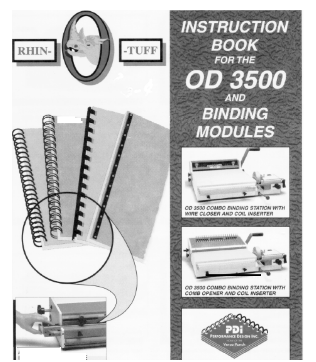
Optional OD 3500 Combo Binding Station,
Modules & Accessories
Topic
Combo Binding Station
1) Attaching Coil Inserter module
Setup Instructions
a) Determine the correct coil
b)
Determine
c) Installing the mandrel on the machine
d) Adjusting the Mandrel bracket
e)
Adjusting the paper stop
f)Adjusting the front table
g)
Forward / off / reverse switch
h) Inserting a coil
i)
Drive wheel stop screw
j)
Cutting a coil
2)
Attaching Wire Closer module
Setup Instructions
a) Determine the correct wire size
b) Inserting the wire into the book
c)
Setting
d) Closing the book
3) Attaching Comb Opener module
Setup Instructions
a) Determine the correct comb size
b) Placing the comb onto the rake
c)
Setting
d) Placing the book onto the comb
e)
Margin settings
the correct
the closing bar height
the comb opener stop
&
Modules
size
size
mandrel
/ lexan
guide
Page Number
3&4
5
6
6
6
6
7
7
8
8
9
9
13
14
14
15
15
17
18
18
18
19
19
Setup Illustrations
Diagram 1
Diagram 2a Coil Inserter
Diagram 2b Coil Inserter
Diagram
Diagram 2d Coil Inserter
Diagram 2e Coil Inserter
Diagram 2f Coil Inserter
Coil Inserter
2c
Coil Inserter
5
7
7
8
9
10
10
Page 4

Topic
1-800-543-5454 www.officezone.com
OfficeZone
Page Number
Diagram 3 Wire Closer
Diagram 4a Wire Closer
Diagram 4b Wire Closer
Diagram 4c Wire Closer
Diagram 4d Wire Closer
Diagram 5 Comb Opener
Diagram 6 Comb Opener
Troubleshooting Coil Inserter Module
Electrical schematic Coil Inserter Module
13
14
15
16
16
17
19
11
12
Page 5
Combo
1-800-543-5454 www.officezone.com
OfficeZone
Binding
Station
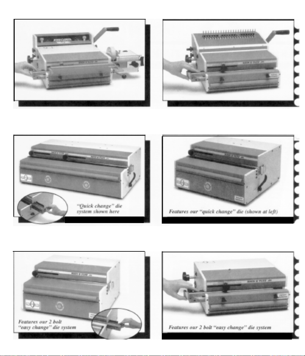
The Combo Binding Station is a base unit that supports three different binding
modules. Each module attaches in a matter of minutes. The attachment
procedure will be located in the module instructional section of this manual.
Coil
Inserter
The Plastic Coil Inserter will bind books up to
diameter up to
1-1/4"
(30mm)
The unit attaches to the right side of the Combo
1-1/8"
(26.6mm) thick using coil
Binding Station or the OD 4000 Punch using two wing nuts for easy installation.
Page 6
Wire closer
1-800-543-5454 www.officezone.com
OfficeZone
The wire closer is capable of binding books up to
wire sizes from
size wires. Each end can be adjusted independently to obtain a perfect close.
The unit attaches to the rear of the Combo Binding Station or the OD 4000
Punch using four knobs.
Comb opener
The comb opener will bind books up to 2” (51 mm) thick. The opener has an
adjustable ring opener control for exact book placement. The
rear of the Combo Binding Station or the OD 4000 Punch using four knobs.
3/16
to 1
-1/4".
It has an adjustable closing bar for the different
1-1/8" (28.6mm)
unit
thick. It uses
attaches to the
All of the above modules can be ordered when ordering the Combo Binding
Station or individual units can be ordered at a latter date. Each unit can be
installed in a matter of minutes. The coil inserter can be attached and kept on the
Combo Binding Station or the OD 4000 Punch permanently. If the Wire closer
module is installed on the Combo Binding Station or the OD 4000 Punch and the
Comb opener module is required: the wire closer will have to be removed so that
the comb opener can be installed. The opposite is also true. It only takes a few
minutes to detach any one of the modules to install any other one.
Page 7

Coil Inserter Module
1-800-543-5454 www.officezone.com
OfficeZone
1)
Installation Instructions:
the
Procedure to attach
4000 Punch.
+
Align the
into
OD 4000 Punch.
+
Use the two wing nuts provided with the coil inserter to attach the unit. Hand
tighten the two wing nuts.
+
Anach the paper
Station or OD 4000 Punch using the
+
Use two black thumb knobs (4) to attach the book table /
the Combo Binding Station or OD 4000 Punch. (The book table
guide has been removed to view
the
+
Plug one end of the power cord into the back of the coil inserter option and
the other end into the wall outlet.
two
the two holes located on the right side of the Combo Binding Station or
book table /
coil inserter onto the Combo Binding
threaded
stop
lexan
Diagram 1
Station
studs
(1) that protrude from the coil inserter option
bracket (2) to the right side of the Combo
two
black thumb knobs (3) provided.
lexan
the
diagram, see diagram
guide in position)
10b to
or the OD
Binding
coil guide to
/ lexan
view
u
Diagram 1
Page 8

Setup Instructions: Diagram
1-800-543-5454 www.officezone.com
OfficeZone
Determine the correct coil size.
a)
2a,
2b,
2c,
2d & 2e
Use a coil that is at least
coil sizes
up
to
3/4" (2Omm).
3/32 (2.5mm)
After
3/4”, use
larger than the book thickness for
a coil size of at least
the book size. The larger the coil compared to the book, inserting will
become much easier.
Determine the correct size mandrel.
b)
There are a total of nine mandrels, which are used for coil sizes
(5mm) up to
1-1/4" (3Omm).
Use the below table to choose the correct
mandrel size to coil size.
Mandrel size
3/16"
1/4"
5/1 6"
3/8"
1/2"
5/8"
3/4
7/8"
1"
Inch
3/1 6"
5/1 6"
3/8"
7/16"
9/1 6"
3/4"
7/8"
1"
1-1/8"
to
to
Coil size mm
1/4”
1/2"
to
l-l/P
Installing the mandrel on the machine
1/8"
3/16”
(5mm-6mm)
(7mm-8mm)
(9mm-1Omm)
(1
mm-12mm)
(13mm-16mm)
(17mm-19mm)
(20mm-23mm)
(24mm-27mm)
(28mm-30mm)
over
+
Place the mandrel (1) into the mandrel holder bracket (2) making
sure
the beveled edge of the mandrel is facing the right side of the
machine. Both guide pins located on the mandrel need to line
both slots on the mandrel bracket. Use the black knob (3) to tighten
the mandrel in place.
+
Adjust the height of the mandrel so the center of the mandrel is the
same height as the center of the book.
Adjusting the mandrel bracket,
d)
+
The mandrel assembly-adjustment knob (4) is located on the right
side of the coil inserter, Move the mandrel bracket assembly towards
the drive wheel for small mandrels and away from the drive wheel for
the larger mandrels.
+
The mandrel holder bracket-adjustment knob (5) can be adjusted to
the left or the right so the leading edge of the coil lines up with the first
hole of the book.
up
with
Page 9

Diagram
1-800-543-5454 www.officezone.com
OfficeZone
Adjusting the paper stop.
a)
Place the book on top of the Combo Binding Station or the OD 4000 Punch
with the right side of the book against the paper stop bracket. Adjust the
paper
stop
(6) so the holes of the book hang over the edge of the Combo
Binding Station or OD 4000 Punch. The holes should hang
just
enough for
or
the
OD 4000 Punch. Tighten the knob
It may be necessary to fine-tune this after a few books are bound for exact
placement.
Adjusting the front table / lexan guide
f)
The
front table/
When the lexan is in the closed position,
will assist the coil to insert smoothly into the book.
lexan
guide with all books regardless of thickness. (SECOND): With the
lexan guide (plastic) in the
machine, it acts as a support
9/16"
thick, it may be necessary at times to start the coil into the book,
then split the book in half using the table to support
then finish the
the
coil to clear the edge of
lexan guide
inserting
of the coil. This method improves productivity.
(7,7a &
open
table
2a
the
Combo Binding Station
located on
7b) has two purposes. (FIRST):
rotated
position,
rotated
(7b) for large books. For book’s over
the paper stop bracket.
on
top
of
You
should
away from
one
half of the book,
over the
the
coil
use
the
edge
(7a),
the
it
Diagram 2b
Page 10

Forward /off / reverse switch.
1-800-543-5454 www.officezone.com
OfficeZone
The forward / off /
position of this switch is the off position and should be placed in this
position when not using the machine. Press the
switch and the coil will rotate into the book. Press the right side (reverse)
of the switch and the coil will exit the book. The reverse feature allows the
coil to be removed from the book. Sometimes this will be necessary when
the leading edge of the coil misses a hole of a single sheet.
reverse
(8) switch has three positions. The center
left
side (forward) of the
Inserting a coil
h)
Place the coil on the mandrel by sliding the open end of the coil onto the
beveled end of the mandrel. Turn the coil so it threads onto
post (9)
forward
(10)
Rotate the coil so it comes close to the edge of the book, but not past the
book. With your right hand, hold the leading edge of the coil and thread it
through the first two holes of the book. This helps align the holes of the
book. Rotate the
gently at first making sure the coil is rotating into the book without missing
and is in front of the drive wheel by one coil. Make sure the
/
reverse switch is in the forward position. Pull the motor handle
down to start the motor and engage the drive wheel (11) to the coil.
lexan
Diagram 2c
the
mandrel
guide on top of the coil. Pull the handle down
Page 11

holes in the sheets or covers. Continue
1-800-543-5454 www.officezone.com
OfficeZone
the book by about one or two coils.
until
the coil is
past the
left side of
i)
j)
Drive wheel stop screw.
The drive wheel stop
hard on the mandrel. It is very important not to have too much pressure on
the mandrel when inserting the larger coils. If
stops on a misaligned sheet, the coil
the book and
this
from happening most of
clockwise to push the wheel away from the mandrel. Load the coil onto the
mandrel and
the motor handle (10)
books and readjust if necessary.
If the mandrel bracket is adjusted after the stop screw has been
adjusted, it will be necessary to readjust the stop screw.
Cutting a coil
There are special cutter crimper pliers (ordered separately) that are used
to terminate the ends of the coil. After the coil is
coil will
make sure the red dot (13) is facing up. Place the cutter on the
the
turn
tuck
itself under
screw
end of the mandrel. Setting
the stop screw counter clockwise while holding down on
Diagram
(12) will prevent
the
time. To
until
the drive wheel touches
the
inside of
2d
wants
to
set the
the
coil opening. To use the cutter,
the
wheel from pressing to
the
leading edge of the coil
tie
itself into a knot between
the stop
screw will prevent
stop screw, turn it
the
coil. Try a few
cut, the
sharp end of
the
Page 12

Diagram
1-800-543-5454 www.officezone.com
OfficeZone
edge of the right hand side of the book. Open the cutter enough so that
the end of the cutter enters the coil by about a
is
level with the book before
may notice the coil wants to twist. You can support the coil with your
fingers as you cut to help stabilize the coil.
these steps on the opposite end of the book. Always make sure to close
you
2e
cut. As
1/4"
Make sure the cutter
you squeeze
Turn
the book over and repeat
the cutters you
Diagram 2f
Page 13

Wire Closer Module
1-800-543-5454 www.officezone.com
OfficeZone
2)
Installation Instructions: Diagram 3
Procedure to attach the wire closer onto the Combo Binding Station or the
4000 Punch.
Place the closer module on the backside of the Combo Binding Station or the
OD
4000 Punch so the closer adjustment knobs are facing the front of the
Combo
Attach the closer with four black knobs (1) provided with the closer module.
Use two knobs on each side to secure the unit in position.
Attach the closing handle (2) either to the right or left side of the closer using
the screw (3) provided with the closing module. Use the allen key provided
with the closing module to secure the handle in place.
The book table /
removed while using the wire closing module. (Combo Binding Station
OD 4000
Binding
Station or the OD 4000 Punch and are pointing up.
lexan
guide & the top paper stop assembly should be
Punch fitted with Coil Inserter Module Only)
OD
or
Diagram 3
Page 14

Coil Inserter Module Electrical Schematic
1-800-543-5454 www.officezone.com
OfficeZone
Power Entry Module
(120
volt
AC)
NOTE: The motor is protected by a
reset automatically after the motor cools.
This product has earned the UL Listing Mark and the UL Listing Mark for
Canada. El 79574
The Cl 3000
with a rest period of 2 minutes after 30 seconds of run time.
The Cl 3000 is also
has been tested with a duty cycle of 4 seconds on, 15 seconds off
know as the Coil Inserter Module OD 4300.
thermal
overload
located
in the motor. It will
Page 15

Wire Closer Module
1-800-543-5454 www.officezone.com
OfficeZone
2) Installation Instructions: Diagram 3
Procedure to attach the wire closer onto the Combo Binding Station or the OD
4000 Punch.
Place the closer module on the backside of the Combo Binding Station or the
OD 4000 Punch so the closer adjustment knobs are facing the front of the
Combo Binding Station or the OD 4000 Punch and are pointing up.
Attach the closer with four black knobs (1) provided with the closer module.
Use two knobs on each side to secure the unit in position.
Attach the closing handle (2) either to the right or left side of the closer using
the screw (3)
with the closing module to secure the handle in place.
The book table /
removed while using the wire closing module. (Combo Binding Station or
OD 4000 Punch fitted with Coil Inserter Module Only)
provided
with the closing module. Use the
lexan
guide & the top paper stop assembly should be
allen
key provided
Diagram 3
Page 16

Setup Instructions: Diagram
1-800-543-5454 www.officezone.com
OfficeZone
a) Determine the correct wire size.
Use the table below to determine the correct wire size for the book thickness.
You can
your book. Covers are not included with the number of sheets column.
insert
more sheets into the wire, but it may affect the appearance of
4a, 4b,
4c & 4d
Wire Diameter Book Thickness
Inch
3/16
1/4
5/16
3/8
7/16
1/2
9/16
5/8
3/4
7/8
1
1-1/4
b) inserting the wire into the book.
First, prep the book by removing the back cover and place it on top of the
front cover. This will position the binding edge of the wire at the inside cover
at the back of the book. Place the book on the edge of a table so the holes
overhang the table a slight amount. Make sure the covers are facing down
and under the main body of text when placing the book on the table.
the narrow loop into the holes of the book with a slight rotating action. Start
with the
remaining holes.
z
6.4
7.9
9.5
11.1
12.7
14.3
15.9
19
22.2
25.4
31.8
left
side and slide your finger along the wire to thread it into the
Inch
1/8
3/16
1/4
5/16
3/8
7/16 11.1
1/2
9/16
5/8
3/4
7/8
1-1/8
z
4.8
6.4
7.9
9.5
12.7
14.3
15.9
19
22.2
28.6
Number of sheets
20lb
30
45
65
80
95
110
125
140
160
190
220
285
80gsm
Insert
Diagram 4a
Page 17

c) Setting the closing bar height
1-800-543-5454 www.officezone.com
OfficeZone
The closing bar is adjustable on each end allowing the operator to achieve a
Pull
perfect close at each end of the book.
way down and adjust both knobs (3) so the
lines up with the line (5)
next
to the wire size you want to close.
the handle on the closer all the
top
edge (4) of the closing bar
Closing the book.
With the handle in the full upright position place the book so the open end of
the wire is firmly pressed against the back
machine (see diagram
top of the book while pushing the book against the back plate.
as you
bar if necessary.
the wide loop by about
that the wire is not closed tight enough is when the covers or sheets fall out of
the book.
pull
the handle (8) down. Inspect the close and readjust the closing
4c
on page 16). The narrow loop (7) should be on the
When
the wire is closed properly, the narrow loop overlaps
1/16"
Diagram 4b
plate
(6) inside the closing
Hold
the book
along the entire length of the book. An indication
Page 18

Diagram
1-800-543-5454 www.officezone.com
OfficeZone
4c
Diagram 4d
Page 19

Comb Opener Module
1-800-543-5454 www.officezone.com
OfficeZone
3) Installation Instructions: Diagram 5
Procedure for attaching the comb
4000 Punch.
Place the comb opener module on the backside of the Combo Binding Station
or OD 4000 Punch so the narrow section of the comb opener is facing the
front.
Attach the comb opener with
opener module. Use two knobs on each side to secure the unit in position.
Anach the comb
opener using the screw (3) provided with the comb opener module. Use the
allen
key provided with the comb opener module to secure the handle in
place.
opener
opener
four
handle (2) either to the left or right side of the comb
onto the Combo Binding Station or OD
black knobs (1) provided with the comb
Diagram 5
Page 20

a) Determine the correct comb size.
1-800-543-5454 www.officezone.com
OfficeZone
Use the table below to determine the correct comb size for the book
thickness. You can insert more sheets into the comb, but it may affect the
appearance of your book. Covers are not included with the number of sheets
column.
Comb Diameter
Inch
3/16
1/4
5/16
3/8
7/16
1/2
9/16
5/8
3/4
7/8
1
1-1/8
1-1/4
1-1/2
1-3/4
2
Placing the comb onto the rake. Diagram 6
b)
E
6.4
7.9
9.5
11.1
12.7
14.3
15.9
19
22.2
25.4
28.6
31.8
38.1
44.5
50.8
Book Thickness
Inch
1/8
3/16
1/4
5/16
3/8
7/16
1/2
9/16
5/8
3/4
7/8
1
1-3/32
1-3/16
1-7/1 6
1-11/16
E
4.8
6.4
7.9
9.5
11.1
12.7
14.3
15.9
19 190
22.2
25.4
27.8
30.1
36.5
42.8
Number of sheets
20lb
30
45
65
80
95
110
125
140
160
220
250
275
300
360
425
Place the comb onto the rake with the fingers of the comb facing the from of
the machine. The solid section of the comb will be facing the rear of the
machine. Make sure the points of the fingers are facing up. Pull the opener
handle down to open the fingers of the comb.
I
80gsm
Setting the comb opener stop. Diagram 5
c)
The comb opener stop knob (4) is located on the rear of the comb opener.
Set the comb opener stop by turning the knob counter clockwise so the comb
opens far enough to place a book on the fingers of the comb, but not to far so
the comb is lying flat with no room for the book.
 Loading...