

Page 1
JUNIOR
Instruction manual
Before using the machine please carefully read the instructions
DOC. N. FM111016
REV. 0
ED. 07.2001
Page 2

INDEX
Chapter 1. Foreword
1.1. Introduction..............................................……... 1-1
1.2. Performances of packaging machine.......……... 1-1
1.3. Machine identification.........................…..…...... 1-1
1.4. Weight and dimensions of packed machine…… 1-3
1.5. Machine weight and dimensions......….......….... 1-3
Chapter 2. Machine installation
2.1. Transport and positioning.................…….......... 2-1
2.2. Environmental conditions.........................……... 2-3
2.3. Electrical connections.............................…….... 2-5
Chapter 3. Machine adjustment and setting up
3.1. Adjustment.............................................…….... 3-1
3.2. Film roll insertion......................................…...... 3-9
3.3. Reticulated plate installation...................….…... 3-9
3.4. Packaging plate adjustment...................…........ 3-11
3.5. Execution of 1^ film sealing...................….….... 3-11
3.6. Introducing the object to be wrapped.……......... 3-13
3.7. Making up..............................................……..... 3-13
Chapter 4. Limits and conditions in the use of machine
4.1. Max. packing sizes................................….….... 4-1
4.2. Items which must not be packed..............……... 4-1
Chapter 5. Film features
5.1. Films to be used..................................……....... 5-1
5.2. Band A calculation...............................……....... 5-1
Chapter 6. Safety standards
6.1 Warnings............................................……........ 6-1
Chapter 7. Ordinary maintenance
7.1. Precautions for ordinary maintenance interventions…………………… 7-1
7.2. Sealing blade cleaning............................…….... 7-1
7.3. Plastic film and other scrap removal......……..... 7-3
7.4. Machine cleaning...................................……..... 7-3
7.5. Rubber and teflon replacement................……... 7-5
7.6. Changing the sealing wire.........................…….. 7-7
7.7. Wiring diagram......................................…..…... 7-9
7.8. Disassembling, demolition and elimination of residuals.. 7-11
Chapter 8. Guarantee
8.1. Certificate of guarantee…......................……..... 8-1
8.2. Guarantee conditions..............................…….... 8-1
9.1. EC declaration of conformity....................…….. 9-1
Page 3

Chapter 1. Foreword
1.1. Introduction
You have bought a machine with outstanding features and performance and we thank you very much
for your confidence in choosing it.
The MINIPACK System is unique in its kind and has achieved worldwide succes with more than
50000 units operating in the field of packaging and wrapping.It is handy, low-priced and protected by
patents at home and abroad.The technological concept underlining its design, as well as the
components and materials used in the manufacturing and testing process are the best assurance of
proper operation and long-lasting liability.
1.2. Performances of packaging machine
Thanks to its particular operating circuit, it can be used both as a sealing and shrinking machine or as
a plain sealing machine (sealing only).
In this case it is possible to pack the object in a soft bag without shrinkwrapping. Technical grade or
food grade films with thickness in the range of 15-50 micron can be used. These products are
manufactured and distributed by MINIPACK Torre S.p.A. The film used in centerfolded execution
can be micropunched or not when running through the micropunches of machine itself. The machine
can carry out up to 300 packages/hour.
1.3. Machine identification
In every communication with the Manufacturer, always
mention the model and the serial number specified on the plate
on the rear part of the machine.
1.4. Weight and dimensions of packed machine
a = mm 1350
b = mm 960
c = mm 800
Weight = Kg 110
Gewicht = Kg 110
Poids = Kg 110
Peso = Kg 110
Page 4
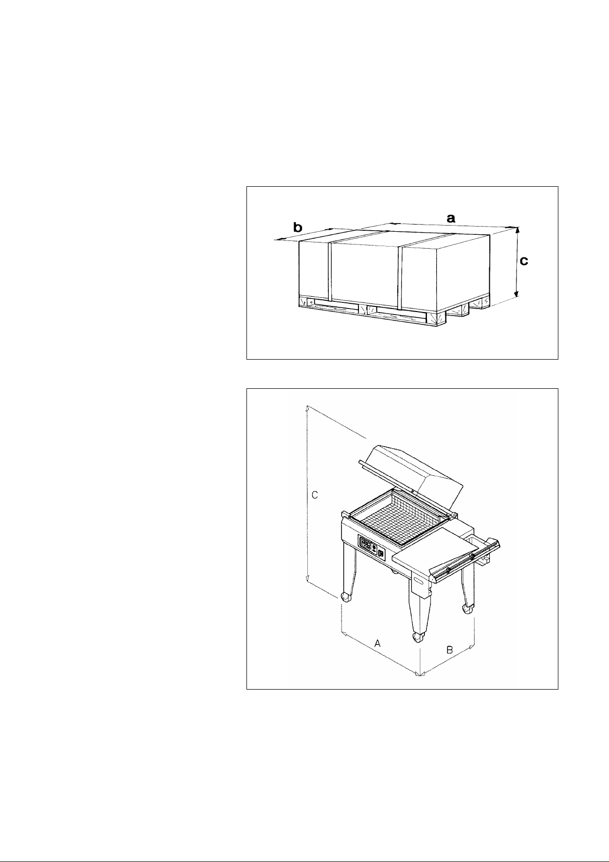
1.5. Machine weight and dimensions
a = mm 1200
b = mm 680
c = mm 1350
Weight = Kg 80
Gewicht = Kg 80
Poids = Kg 80
Peso = Kg 80
a = mm 1350
b = mm 960
c = mm 800
Peso = Kg 110
a = mm 1200
b = mm 680
c = mm 1350
Peso = Kg 80
Page 5
Chapter2. Machine installation
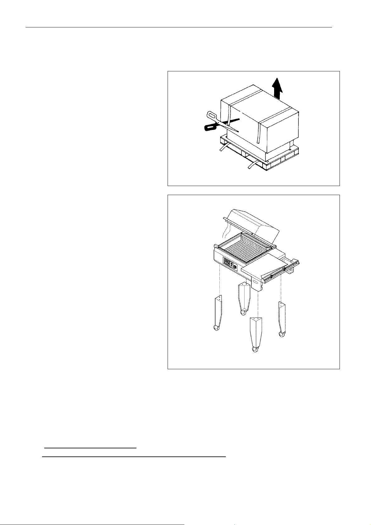
2.1. Transport and positioning
It is recommended to handle with great care during transport and positioning!
Cut strap with scissors and remove the
cardboard.
Remove the cardboard containing the
supports.
Unscrew the 4 locking screws.
Remove the machine from the pallet (to lift
the machine always grip it by the ends. Do
not lift it from film roll support!).
Place the 4 supports on the machine.
Remove the upper hood by cutting the
strings.
2.2. Environmental conditions
Place the machine in a suitable environment free from humidity, gases, explosives, combustible
materials.
Working environmental conditions:
• Temperature from + 5°C to + 40°C
• Relative humidity from 30% to 90%, without condensation
Machine safety factor = IP20
The aerial noise made by the machine is lower than 70 dB
Page 6
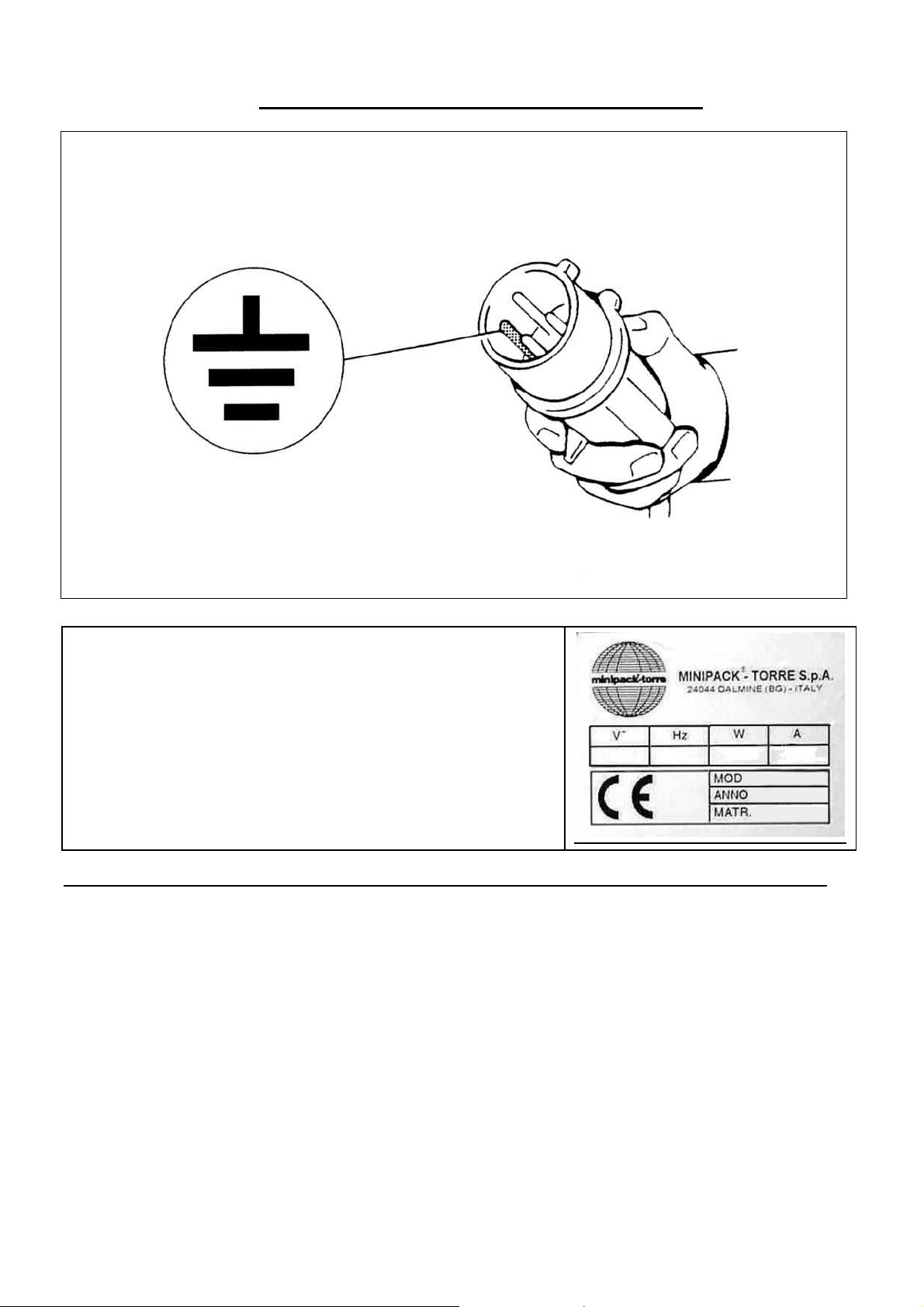
2.3. Electrical connections
OBSERVE HEALTH AND SAFETY REGULATIONS!
GROUNDING OF THE UNIT IS OBLIGATORY!
Before executing electrical connections, make sure the mains
voltage matches the one on the plate on
machine rear and that the earthing contact complies with the
safety rules in force. In case of doubts about the mains voltage,
contact the local public supply Company.
Chapter 3. Machine adjustment and setting up
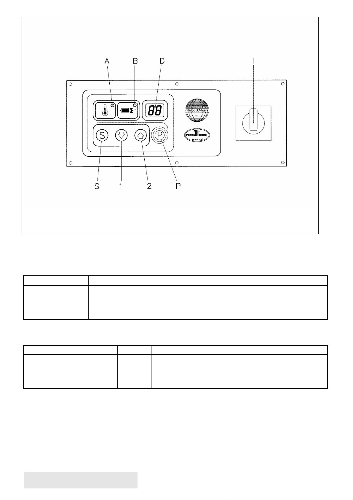
3.1. Adjustment
I-
Main switch
Temperature warning light
A-
Sealing warning light
B-
Display
D-
Variables selection switch
S-
Programs selection button
P-
Adjusting button
1-
Adjusting button
2-
Page 7
ELECTRONIC BOARD FEATURES
The machine is equipped with 6 selectionable programs:
Program nr. Program features
P1
P2
P3
P4 - P5 - P6
The most complete program is made by 3 variables which can be modified (in case it is not
possible to set one of them, such a variable will obviously not appear on the display):
Variable Field Field features
1. Sealing
2. Fan delay after sealing
3. Temperature
PHASE NR. 1 = SWITCHING THE
MACHINE ON
Push the main switch (I) into pos. 1.
Sealing only
Sealing + shrinking
Sealing + delayed shrinking to sealing end
Sealing + shrinking
00 ÷ 1.6
0 ÷ 9
0.0 ÷ 99
values expressed in seconds
values expressed in a tenth part of a second
corresponds to 120.....318°C (2°C each point)-(medium
value 75)
Page 8

Before using the machine, wait until the adjusting temperature is reached. This is signalled by the
extinction of the warning light (A). It takes 10 minutes to the heating chamber to get hot. The display
(D) turns on the number of the currently selected program will appear.
PHASE NR. 2 = PROGRAMS
SELECTION
Push button (P) to select the number of the program.
PHASE NR. 3 = VARIABLES
PROGRAMMING
Throught button (S) it is possible to look throught the variables of the selected program, while
through buttons ( 1 ) and ( 2 ) the memorized values can be modified. Once the value has been set,
push the S button and then release it; the LED of the next function will light up. Set the value of the
variables as previously described. To validate modifications, presso button (S) until the number of
the program appears on the display. The fan delay time after sealing can be modified; there is not a
LED indicating this variable which is shown with an “ r “ on the left display,while the right one
shows the time which has been set. At the end of all variables to be adjusted, the display will show
the code of the program just chosen (for example P1). N.B.: In case during programming the FC limit
switch is being pressed, the unit quits the scheduling, the selected program is executed and the
display shows the number of the program.
PHASE NR. 4 = PERFORMANCE
Once all adjustments have been made, the machine is ready to start working.
In case of “ANOMALY” the display will show as follows:
Machine has been switched on when the hood was lowered. Lift the hood up.
E 1
Machine has been switched on when the (S) button was pressed. Release the button. In case the
E 2
error signalling still persists, check the correct functioning of the button.
Working temperature hasn’t been reached in the set time (10 min.). Check the correct positioning of
E 3
the feeler. Check heater and fuses. Reset through (P) button.
Temperature is higher than 370°C or feeler has been interrupted. Switch the machine on to reset.
E 4
3.2. Film roll insertion
Insert the roll of film on the roller (5)
and block it through the centering cones
(6).
Position the roller on the film roll
support.
Run through the micropunches (7).
Run the film lower layer under the
packaging plate (8).
Run the film upper layer over the
packaging plate (8).
3.3. Reticulated plate installation
Page 9

The reticulated plate (9) can be placed
according to the height of the product
to pack. To position it follow this
procedure:
Pull the reticulated plate in direction of
the arrows
Remove it from the stops
Position the plate on the stops at the
required height
N.B.: For a proper packaging the
reticulated plate must be positioned
so that film sealing is at the half of
the package height.
3.4. Packaging plate adjustment
The packaging plate (10) must be
adjusted according to the width of the
item to be packed, leaving a space of
about 1-2 cm between the item and
the sealing edge.
3.5. Execution of 1^ film sealing
Page 10

Place film as shown in the picture to
carry out the first seal.
Lower the handle of the cover with
your left hand and make a pressure of
10-15 Kg. Machine will automatically
operate and the first seal will be
carried out on the side of the film.
With the right hand detach the film
from the sealing blade. Film is now
ready to carry out wrapping.
3.6. Introducing the object to be wrapped
With the left hand slide on the
packaging plate the quantity of film
necessary to contain the product to
be packed.
Introduce the product into the bag
using the right hand and make it
slide to the left until it is layed on
the screen leaving a little space fo
about 1-2 cm to allow the passage of
air for shrinkwrapping.
3.7. Making up
Page 11

By pushing the cover handle with a
pressure of 10-15 Kg. the cover rests
on the sealing blade; by pinching the
film, it is automatically sealed on
the open sides (right and front). In
case you have selected the function
“SEALING +
SHRINKWRAPPING” you will see
the film shrink onto the product.
Slightly decrease the pressure on the
cover handle to allow film detach
from the sealing area on the inside.
With the right and detach the film
from the sealing blade towards the
outside.
Chapter 4. Limits and conditions in the use of machine
4.1. Max. packing sizes
a = mm 500
b = mm 380
c = mm 250
N.B.: max. dimensions shown on above scheme are referring to the max. dimension of the single
package.
Refer to chapter 5.2. to get max. dimension of package (b x c); the addition of (b + c) is equal to
film roll width 100 mm.
4.2. Items which must not be packed
Page 12

The below listed products must absolutely not be wrapped to avoid damages to the machine and
seroius injuries to the
operator in charge:
Chapter 5. Film features
5.1. Films to be used
Machine can work with all
shrinkwrapping films with
thickness 15-50 micron
manufactured by ”MINIPACKTORRE S.p.A.”. The special
features of our films (which may be
customized with drawings and text)
assure their outstanding reliability,
with regard both to compliance with
laws in force and to an excellent
machine performance.
A=mm 500 MAX
D=mm 250 MAX
d=mm 77
5.2. Band A calculation
Band A = b + c + 100 mm
Wet and unstable products, liquids of any kind and density in fragile
containers, flammable and explosive materials, pressurised gas cylinder of
any kind, bulk and volatile powders, bulk materials with grain size smaller
than the holes of the reticulated plate, any materials and products not listed
but which might harm operator and cause damages to the machine.
Chapter 6. Safety standards
Page 13

6.1. Warnings
Do not touch the sealing blade (12)
soon after sealing by reaching beyond
the safety guard (13).
Danger of burns due to residual
heat on the sealing blade.
Do not keep on sealing in case the
sealing blade breaks (12).
Replace it at once.
Page 14

Do not touch the chamber closing flap
(14) during warm-up function..
Danger of burns
ATTENTION !
Every time you turn the machine off,
it is recomended to leave the upper
hood open (as shown in the drawing).
Make sure the film roll is properly
lodged (16).
Page 15

Chapter 7. Ordinary maintenance
7.1. Precautions for ordinary maintenance interventions
BEFORE PROCEEDING TO MAINTENANCE, SWITCH THE MACHINE OFF AND
DISCONNECT IT BY OPERATING
ON THE MASTER SWITCH.
7.2. Sealing blade cleaning
Using a dry cloth, wipe off the
residues clinging to the sealing
wire: do this at once after sealing
since they are easier to
remove when still warm.
Lubricate the welding blade
periodically with the supplied nonadhesive spray.
7.3. Plastic film and other scrap removal
Page 16

Wait for the machine to cool down
completely before removing any
scraps stuck to the hot parts of the
machine
(e.g. , on the flaps of the heat
chamber). If the lower cover requires
cleaning (where the fan is installed),
remove the reticulated plate and take
out any pieces that may have fallen
inside.
For a more careful cleaning of the
lower bell we recommend to use a
vacuum cleaner.
7.4. Machine cleaning
Use a cloth moistened with water
for the cleaning of the machine.
For cleaning the bell inside and
outside we recommend to use a normal
detergent for glass cleaning.
Do not use any detergents with
solvents which could damage the
bell and reduce the transparency.
7.5. Rubber and teflon replacement
Page 17

When the Teflon-strikers (17) are
worn out, replace them with spare
parts, paying attention that the
application is linear
and even.
Before applying the Teflon selfadhesive strip clean the rubber part
(18) with a detergent.
If also the rubber (18) is damaged,
replace it as follows:
Remove the old rubber, clean its
housing, apply some drops of glue
in the housing, insert the new rubber
in a linear way, clean the rubber
with a detergent, and apply the selfadhesive Teflon-strip.
Page 18

7.6. Changing the sealing wire
To replace the sealing blade (19) follow this procedure:
• Disconnect power to the machine
• Unscrew the three screws (20), (21), (22)
• Remove the old sealing blade
• Clean the housing and if necessary replace the insulating teflon (23) of the central clamp
• Insert the new sealing blade starting from the central clamp and tighten the screw (21)
• Trim the new sealing blade according to the holes of the pistons (24) and (25)
• Complete the insertion if the sealing blade in the whole housing
• Push the rear piston completely onwards (25) towards the sealing blade to make it enter the hole
of the piston itself and then tighten screw (22)
• Push the front piston (24) completely onwards towards the sealing blade to make it enter the hole
of the piston itself and then tighten screw (20)
• Trim the teflon projecting from the central clamp
• Make sure that the sealing blade (19) is well positioned and in tension
Page 19

7.7. Wiring diagram
IG Main switch M Fan motor
FU Fuse 10.3X38 (AM 16A 450V) KM1 Oven resistors contactor
F1 Fuse 5X20 (T 6.3A 250V) KM2 Cutting contactor
F2 Fuse 5X20 (T 6.3A 250V) TC Thermocouple
EH Oven resistors FC Machine cycle limit switch
EH1 Cutting heater UCC Monitoring and control unit
TR Cutting transformer
7.7. Schema elettrico
Page 20

7.8. Disassembling, demolition and elimination of residual
ATTENTION!
All operations about disassembling and demolition must be done by qualified
personnel with mechanical and electrical expertise required to work in security
conditions.
Proceed as follows:
1. disconnect machine from power mains
2. disassemble components
All wastes must be treared, eliminated or recycled according to their classification and to the
procedures in force established by the laws in force in the country the equipment has been
installed.
Page 21

Chapter 8. Guarantee
Model and Serial Number:
Equipment manufactured by minipack-torre is warranted to be free of defects in parts and
craftsmanship for a period of one (1) year from the date of installation, or 15 months from the
invoice, whichever occurs first, minipack-america's exclusive obligation under this warranty
is limited to repairing or, at its option, replacing any minipack-torre part that is determined by
minipack-america to be defective. The warranty is for the original purchaser of new equipment.
Component subsystems manufactured by minipack-torre carry the warranty as stated herein.
The warranty does not apply to subsystem component parts which are not manufactured by
minipack-torre. Subsystem component parts not manufactured by minipack-torre shall be
subject to any warranty of its manufacturer.
This warranty shall not apply to damage resulting from installation, modification, or repair by
anyone other than a minipack-america authorized distributor/dealer. Nor shall it apply to any
equipment which has been subject to accident, alterations, neglect, misuse or improper
maintenance.
In the event of highly corrosive or high moisture applications, special protective coatings or
stainless steel construction might be needed.
minipack-torre and minipack-america shall not be liable if minipack-torre equipment or
components are used with accessory equipment not manufactured by minipack-torre.
Representations and/or warranties, by whomever made (even if made by minipack-america
authorized distributors/dealers), which are inconsistent with the terms herein shall not
constitute a term of the mininpack-torre or minipack-america express warranty and shall not be
binding on minipack-torre or minipack-america.
THE LIMITED WARRANTY SET FORTH ABOVE IS THE SOLE AND ENTIRE
WARRANTY PERTAINING,TO THE PRODUCT AND IS IN LIEU OF AND EXCLUDES
ALL OTHER WARRANTIES OF ANY NATURE WHATSOEVER, WHETHER
EXPRESSED, IMPLIED OR ARISING BY OPERATION OF LAW, INCLUDING, BUT
NOT LIMITED TO ANY IMPLIED WARRANTIES OF MERCHANTABILITY OR
FITNESS FOR A PARTICULAR PURPOSE. THIS WARRANTY DOES NOT COVER OR
PROVIDE FOR THE REIMBURSEMENT OR PAYMENT OF INCIDENTAL OR
CONSEQUENTIAL DAMAGES OF ANY TYPE, MANNER OR DEGREE, AND ANY
LIABILITY BY MINIPACK-TORRE OR MINIPACK-AMERICA FOR SUCH
INCIDENTAL OR CONSEQUENTIAL DAMAGES IS HEREBY DISCLAIMED. Some
states do not allow this exclusion or limitation of warranties and/or damages, so the above
limitations and/or exclusions might not be applicable to you. This warranty gives you specific
legal rights, and you might also have other rights that vary from state to state.
 Loading...