

Page 1

1
Office Zone
1-800-543-5454
1-800-543-5454
(801) 927-3026
Model 912
Cutsheet Signer
By Martin Yale
Installation, Operation and Maintenance Instructions
Model 912 Specifications
FUNCTIONAL
Paper Weight.…………………………..16 to 70 lb bond
Paper Width.. ………………………………2-3/4” to 14”
Paper Length………………………………..2-3/4” to 14”
Continuous Feed Load Capacity…………………..1 -3/8”
Speed………………………8,400 (3-1/2”) form per hour
Signature Spacing……………….2-1/2” W x 1-3/8 H area
Anywhere on the document
Optional……………………………….…Signature Plates
PHYSICAL
Color………………………………………………..Grey
Dimensions.………………..29” W x 12” H x 19 -1/2” D
(plus receiving tray)
Weight……………………………………66 lbs. (30 kg)
Shipping Weight…………………………73 lbs. (33 kg)
ELECTRICAL
Power……………………….110 / 120 VAC, 50 / 60 Hz
Optional…………………….220 / 240 VAC, 50 / 60 Hz
Fuse………………………..2A (1A for 220 / 240 VAC)
Introduction………………………………….
Features…………………………………..
Nomenclature…………………………….
The control panel………………………..
Installation……………………………….
Programming……………………………
Operation……………………………..
Troubleshooting………………………
Maintenance…………………………
Diagnostic Tests………………………..
Error Message Explanations…………….
Parts Diagram…………………………..
Parts List……………………………….
Wiring Diagram………………………..
SERIAL NUMBER ________________
Table of Contents
Introduction
Thank you for selecting the Martin Yale Model 912 Cutsheet Document Signer /
Imprinter. This programmable electronic signer was designed to provide a high level of
security, operational flexibility and easy programming. Each signer component has been
engineered to perform reliably and is 100% factory tested to ensure years of quality
service.
Page 2

2
We recommend that you familiarize yourself with the signer by carefully reading this
manual. Reading and thoroughly understanding this manual will help you avoid the most
common problems and eliminate operator -associated errors. Remember, signature plates
cannot be manufactured for every application they must be custom made. Therefore,
signature plates must be ordered separately. If you did not order signature plates when
you ordered your 912, do so now by calling your dealer.
Warning – Never connect power to the machine until you are ready to set up and
operate the 912. This machine contains moving parts. During setup, operation, and
maintenance keep hands, hair, loose clothing and jewelry away from all moving
parts. Serious bodily injury could result. Service, or disassembly of covers should
only be performed by qualified personnel with the power disconnected and locked
out.
Features
1. Security
a. Five-digit security codes at one or two levels guard against unauthorized usage.
b. Cover lock restricts access to signature plates until executive security codes in entered.
c. Executive control of batch quantity is optional for each run.
d. Lock key required to reprogram security codes and stored setups
e. Standard tri-colored ink roller (red, blue and purple).
2. Convenience
The Martin Yale Model 912 Cutsheet Signer is a table top office appliance that will sign
or imprint messages on checks and a wide variety of documents. Customized signature
plates are easily ordered and installed. Signature locations are entered by jogging the
document to reference line on the 912. No form measurements or calculations are
necessary. Signature locations and batch control are easily entered or selected from five
stored setups. Variable signature placements, electronically controlled, can be easily
adjusted during a run. Long life pre-inked roller is spring loaded for easy removal and
quick access to signature plates.
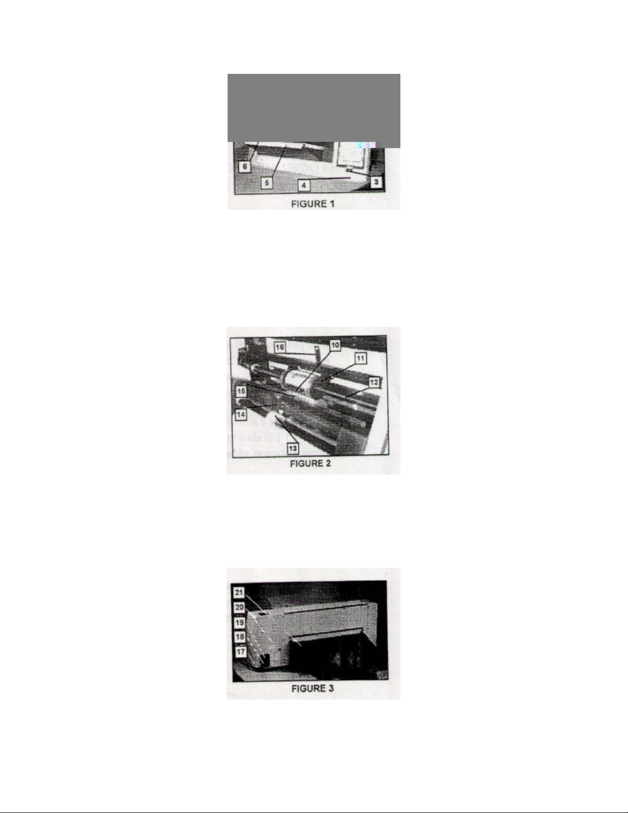
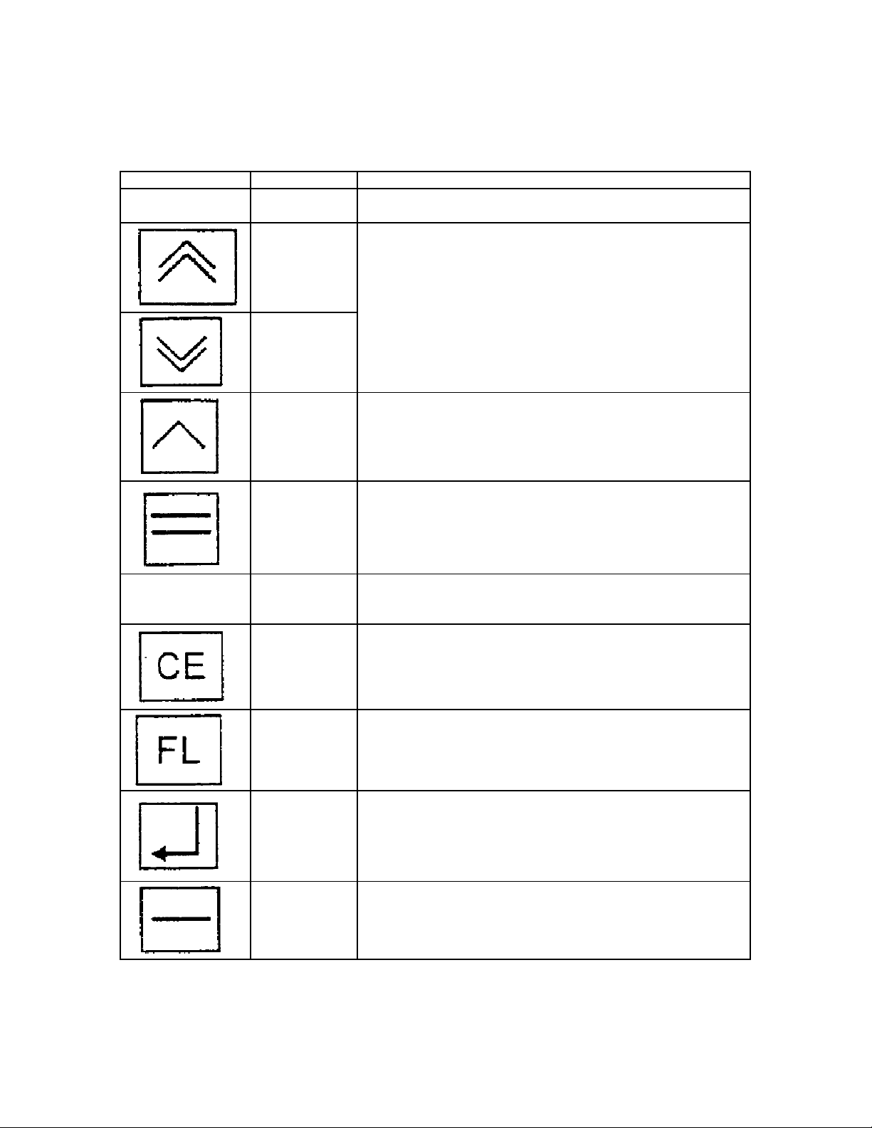
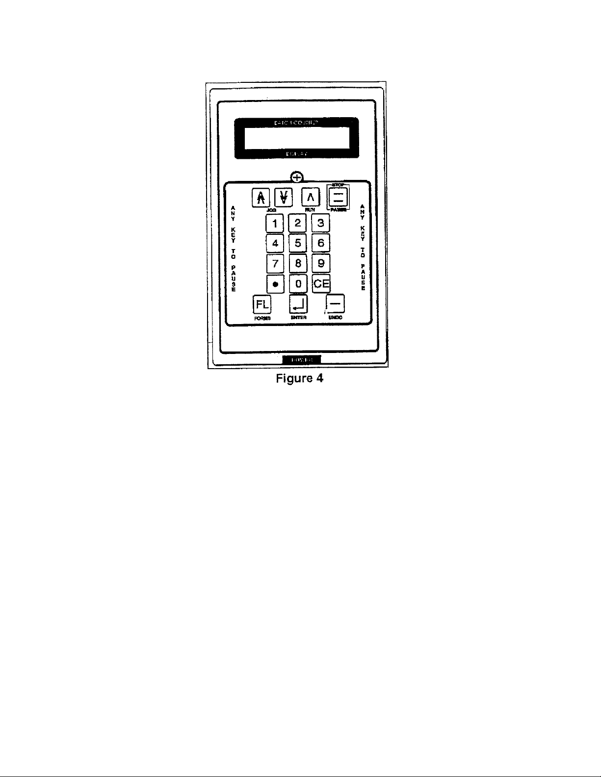
Nomenclature (see figures 1, 2 and 3)
1. Ink Rollers – is saturated with fast-drying permanent ink and rotates freely on the ink roller shaft.
The ink roller guide holds the ink roller in position. The ink roller shaft is spring-loaded into
floating brackets.
2. Control Panel – has a 20 -character by 2-line display at the top and a keypad below.
3. Power Switch – has international symbols. 0 for OFF and | for ON.
4. Bezel – durable, flame -retardant ABS
5. Feed Table – supports the document to be signed
6. Paper Guides – maintain document alignment during feeding
7. Bracket – one each side supports the ink roller shaft
8. Ink Roller Adjustment Screw – one each side, determines the amount of contact between the ink
roller and signature plates.
9. Cover Lock – one on each side of the cover
Page 3
3
10. Signature Plate Holder – clamp is spring-loaded for easy installation and removal of signature
plates.
11. Idler Wheels – a pair of rollers that feed the paper after the paper leaves the drive rollers.
12. Signature Plate Shaft – supports and drives the signature plate holder
13. Feed Roller – feeds the document from the bottom of the stack into the drive rollers one at a time.
14. Retarder – adjusts to allow only one document to feed at a time
15. Platen – supports the paper during impression
16. Idler Tension Spring – puts tension on the idler disc.
17. Line Cord – connects the signer to the AC power source.
18. Fuseholder – contains the replaceable power fuse
19. Key Switch – is used only to program the security codes and the stored setup parameters.
20. Serial Label – shows the serial number, electrical ratings, and agency approvals.
21. Receiving Tray – catches the signed documents. The backstop adjusts to different document
lengths.
Page 4
4
The control panel (see figure 4)
Key Name Function
Batch Counter
Display
Jog Forward
Key
Jog Reverse
Key
Run Key Is used at the last step in setup to start the signing process
Pause / Stop
Key
Keeps a running count of documents signed. During setup, this
display informs and prompts the operator
Are used during setup to align the signature line with the
reference line. Each jog step is approximately 1/16”
Is used during operation to stop or pause the signing process.
Any other key will do the same.
Number and
Decimal Point
Keys
Clear Entry
Key
Forms Length
Key
Enter Key Is used to define signature locations, and to skip the five second
Undo Key Is used to back up one step during setup or programming. Note –
Are used to enter security codes and respond to choices offered
by the prompts
Is used to clean an incorrect entry
Is used at any time to have the signer display the current setup
cover access period.
The UNDO Key is not used to clear an incorrect numerical entry,
because it will back up to the previous mode choice.
Page 5
5
Installation
After careful unpacking, place the 912 on a flat level surface for operation. Remove the plastic
bag containing the programming keys and hex key (Allen) wrench. Plug the power cord into an
AC outlet and press the POWER switch. Make sure the programming key is out of the key switch
in the rear. Note – In this manual, prompts and messages are shown in quotation marks, e.g.,
“New Executive Code?”.
When prompted for the executive code, press the “1” key 5 times. Open the cover within 5
seconds. If a mistake is made, press CE and re-enter 11111. (The factory preset executive
security code is 11111. If the display shows invalid code when this number is used, use the lock
key to reprogram the executive security code. See Programming Secti on of this manual)
The platen (backup roller) is normally held in place by friction. For shipping, the platen has been
tightened down at the factory. Adjust the platen’s sliding friction by using the Allen wrench
provided to turn the platen setscrew 3 / 4 turn counterclockwise from snug. Remove the brown
packaging tape that is holding the signature plate holder and platen in place. Also remove the tape
from the Plexiglas reference guide.
1. Positioning the signature plate holder
Remove the ink roller shaft by grasping each end and sliding the shaft to the left or right until it
clears the bracket. Set the assembly (ink roller, guide and shaft) aside, with the flat side of the ink
roller guide down. Note – Be careful to keep the shaft horizontal so the ink roller does not slide
off the end of the shaft. Rotate the signature pate shaft manually until the setscrew in the signature
Page 6

6
plate holder is accessible. Use the hex key (Allen) wrench provided to loosen the setscrew. Slide
the signature plate holder left or right to the approximate location of the signature block on the
documents. * Note – The idler disk assembly moves with the signature plate holder. Retighten
the setscrew.
Slide the platen into plate directly beneath the signature plate holder. The platen is held in place
by friction.
Caution – Do not tighten the setscrew in the platen.
2. Installing the signature plates
The 912 requires two identical signature plates to be installed on the signature plate holder.
Install a signature plate by sliding the plate holder clamp to the left and slipping the notch in the
signature plate onto a pin in the right end of the plate holder. Release the plate holder clamp.
Manually rotate the signature plate shaft backwards until the signature plate touches the platen
from behind. Slight contact between the signature plates and the platen prevents the first signature
plate from falling off when the opposite signature plate is installed or removed. Install the second
signature plate in the same manner as the first. Ensure that both signature plates are seated
correctly, flat against the signature plate holder.
3. Installing the ink roller
Caution – The ink roller is saturated with permanent ink. Always use the protective glove
supplied with your 912 (or similar hand protection) when working with ink rollers.
Put the ink roller back onto the machine by first positioning the ink roller guide so that it straddles
the signature plate is facing the ink roller guide at the top. Insert the ink roller shaft first into one
brackets, then the other. The springs inside the brackets hold the shaft in place. The ink roller
adjustment screws determine the inking of the signature plates.
4. Adjusting the ink roller
The depth of inking is adjusted at the factory. If readjustment is necessary, first rotate the
signature plate shaft so that a signature plate is facing the ink roller. Look in from the side to see
the gap between the signature plate and the ink roller. Adjust the ink roller adjustment screws
with a crosspoint (Phillips) screwdriver until the ink roller just contacts the rubber stamp evenly.
Turn each screw one more turn counter clockwise.
5. Installing the feed tray
At each end of the retarder bar, raise the feed tray latches and use the 3/32” hex key (Allen)
wrench provided to snug the screws. Tilt the feed tray up and slide the top black hook on each
side of the feed tray onto its respective support pin. Lower the feed tray into position. Release the
tray latches and tighten the screws to lock the tray latches in position.
6. Installing the receiving tray
Slide the receiving tray hooks into the slots in the rear panel window and lower the receiving tray.
Install the backstop on the receiving tray in the shortest position that will allow a sample form to
lay flat on the receiving tray. Note that the tabs on either end of the backstop fit into the slots in
the receiving tray, providing length adjustment from 3” to 17” in 2” increments.
7. Adjusting the retarder
Page 7

7
Select a sample sheet of the thinnest paper to be processed through the 912. Slide the feed tray
paper guides apart to the stops. Use the Diagnostic Test #9 to run the paper drive motor as
follows. Restart the 912 by turning it off and back on again. Insert the key into the lock in the
rear panel and turn the key clockwise. At the prompt “or 2 to Change Stored Forms”, press STOP
and then press the 9 key 5 times. At the prompt “Diagnostic Tests, Depress 1-9”, press the 9 key.
After 2 seconds, press the RUN key.
Pull out the Feed Tray Extension. Hold the sample form by the trailing edge, 5” above the feed
tray. Feed the leading edge of the sample form into the machine to just below the retarder bar (1 /
2” past the line of contact between the feed wheel and the retarder). Turn the retarder thumbwheel
clockwise until the feed wheel exerts a constant pull on the sample form. Release the form and let
it pass through the 912. Press the STOP key.
Programming
Two features of the 912 can be programmed. One is the executive and operator security codes that
allow the 912 to operate. The other feature is the setup parameters of signature locations and
batch control. Note – In this manual, prompts and messages are shown in quotation marks e.g.,
“New Executive Code?”.
Page 8

8
program number. Those parameters are: number of signatures per sheet, the location of each
signature, and the batch mode. If that stored setup is to be kept under that program number, press
CE and enter another program number.
Press the “Enter Key to Re-Define” if you wish to modify that stored setup. The display will
prompt “Define New Signature Locations”. Follow instructions at “Load One Sheet; Use Jog
Forward Key” to advance a sample form into the signer. When the signature line on the form is
under the reference line, press the ENTER Key. Follow the prompts to define other signature
locations on the form. After the last signature location has been defined, press STOP. The signer
will feed out the sample form and prompt for a “Batch Mode?”.
Select “Count Up” if the signer is to sign and count without limit. Select “Count Down” if the
signer is to sign a predetermined quantity. If desired, follow the prompts to select another form
number to re-define.
Operation
Follow the display prompts to enter codes (passwords). Open the cover to install signature plates
or adjust the horizontal location of the signature block. Select a stored setup or enter a setup
manually by jogging a sample from though the 912 to define the new signature locations. Select
the batch mode (count down from a preset quantity or count up until paper is depleted), and
initiate the signing process.
At each step, the 912 displays a prompt for an entry or action. At some of the steps, supplemental
messages are displayed.
Note – In this manual, prompts and messages are shown in quotation marks e.g., “New Executive
To eliminate supplemental messages, press any key immediately after power is switched on,
before the prompt “Enter Executive Code” appears.
1. Setup Steps
The display prompts and messages are self-explanatory. For reference, here is a list of steps for
setup and the choices available at each step.
a. “Enter Executive Code” – Enter the 5-digit code that has been programmed as the
b. “Cover May Be Opened” – If you are installing or removing the signature plates, or if
executive security code. Each digit entered will be acknowledged by the moving cursor
in the display. If you make an incorrect entry, press CE and try again. If the code is not
accepted, use the lock key to reprogram the executive security code. (See programming
Section of this Manual.) The factory preset executive code is 11111.
If a form is in the Model 912 and blocking the paper sensor while the prompt “Enter
Executive Code” is displayed, remove any forms from the feed tray and press RUN to
pass the form out quickly. This method of clearing the Model 912 is faster than using the
JOG Keys.
you need to adjust the signature plate holder horizontally, open the cover within 5
seconds. To proceed to the next step, press ENTER at this prompt. The 912 will
sequence to the next step automatically if this prompt is displayed for 5 seconds, or if the
cover is opened and closed. Once the cover is opened, it may be left opened indefinitely.
Once the cover is closed, it will be locked until the executive code is entered again.
Page 9

9
c. “Press 1 for Stored or 2 for Manual” If you desire to use the most recent setup again,
press CE at this time. The 912 will skip this step and the next two steps. To select a
stored setup, press key 1, then press a key 1-5 for the setup number. The 912 will then
skip the next two steps. To “Define New Signature Locations” for the current setup,
press key 2.
d. “Load One Sheet. Use Jog Forward Key” On the feed tray, adjust the paper guides for
the width of a sample form. Place it in the feed tray and use the JOG FORWARD Key to
advance the sample form until the first signature line is directly below the reference line
on the clear plastic bar. Press ENTER to define that location. Repeat the JOG
FORWARD and ENTER procedure until the last signature location has been defined. To
feed out the sample form, press STOP.
Note – The retarder must be adjusted for correct paper feeding. Section Installation
section 7, Adjusting the Retarder.
e. “Press 1 for Count Up or 2 for Count Down” When the count up mode is chosen, the
BATCH COUNTER keeps a running total of signatures. The 912 will continue to run
until it is out of paper. When the count down mode is chosen, the desired number of
signatures must be entered to preset the counter before each batch is run.
f. “Enter Batch Amount” – If the count up mode was chose, the 912 will skip this step. If
the count down mode was chosen, a quantity must be entered, followed by ENTER.
g. “Enter Operator Code” – Enter the operator code if it has been programmed to be
different from the executive code. The factory preset operator code is 22222. If the
operator code has been programmed to be the same as the executive code, the 912 will
skip this step. (To reprogram the operator code, see Programming Section of this
manual.)
h. “To Begin, Press the RUN Key” – Fan the stack of forms so the stack is tilted away from
the 912. (See figure 5.) Place the stack on the feed tray with the bottom form at the line
of contact between the feed roller and the retarder roller. To begin the signing process,
press the RUN key. The 912 will run until another key is pressed, or the paper is
depleted, or the count is down to zero (count down mode). After a few forms have been
signed, you may want to pause the 912 to verify the signature alignment and to ensure the
forms are stacking correctly. When paused, the 912 displays “Batch Count _, HOLD
RUN to Continue”, with the HOLD flashing. Press RUN to continue.
The 912 automatically terminates the run if no paper feeds in 8 seconds, or if the count is
down to zero (count down mode). To manually terminate the run, press STOP, then press
UNDO. The 912 then displays “Final Batch_, Press Any Key”. To return to the prompt
“Enter Executive Code”, press UNDO again. If a form has been left in the Model 912,
removed the stack from the feed tr ay and press RUN to pass the form out quickly, or use
a JOG Key.
Insert image here
2. Adjusting the signature locations
To adjust a signature location during a run, first press STOP to pause the 912. Then, press the
number of the signature you wish to move. For example, press the 2 key to select the 2nd signature
on the form. The 912 prompts “Adjust Signature Number 1 (2, 3, or 4)”. To move the selected
signature up, press the JOG FORWARD Key. To move the selected signature down, press the
JOG REVERSE Key. The 912 acknowledges “Sig #1 (2, 3, or 4) Moved Up (Down) 1/16 of an
Note – Only one signature location adjustment can be made during each pause.
3. Storing the adjusted signature locations
Page 10

10
To program the new signature locations into a stored setup, first complete the run. Pres UNDO
twice to return to the prompt “Enter Executive Code”. Press the FL Key. Insert the lock key into
the lock on the rear panel and turn the key clockwise. The 912 prompts “Form Number (1-5) to be
Updated”. Press the number of he stored setup to be updated. The 912 acknowledges
“Programmed Form Number 1 (2, 3, 4 or 5) Updated”. Then the 912 reminds you to “Turn Key to
Continue”. Turn the lock key to the vertical position and remove it.
Operator’s Troubleshooting Guide
If an error is made during setup or programming, the 912 display a specific message describing the
error and prescribing a corrective action. Follow the prompt to retry the last step. If the error
message is repeated, turn the 912 off and on again, and repeat the setup or programming steps. To
clear an error message, press CE. Following is a listing of possible and corrective actions. Also
see Section Diagnostic Tests and Section Error Code Explanations.
1. No message in the display – Make sure the power cord is plugged into a live AC outlet.
Check the power fuse in the rear panel for an open filament or a burnt spot. If necessary,
replace the fuse with the same type and rating.
2. Any error message in the display – Press CE and try again. If the error message repeats call
your service technician for assistance.
3. First prompt after power on is not “Enter Executive Code” Check to see that the lock key is
out of the rear panel switch.
4. Security code is not recognized – Press CE and re-enter your se curity code. If the security
code is still not recognized, reprogram it by the procedure in the Programming Section of this
manual.
5. Display indicates “Cover May Be Opened”, but cover is stuck Rock the cover up and down
at both sides while the message is displayed. If necessary, press UNDO and re-renter the
security code.
6. Signature plate holder won’t slide Check to make sure that the setscrew is loose. Gently tap
the right end of the signature plate holder.
7. Platen won’t slide – Gently tap either end of the platen. Slide the platen back and forth
several times. If necessary, loosen, but do not remove, the setscrew using the hex key (Allen)
wrench provided. (The factory setting for proper tension is 3 / 4 turn counterclockwise from
snug.)
8. Cover won’t close completely – Check to see that the ink roller assembly was installed with
the flat side of the ink roller guide at the top.
9. “Cover is OPEN” message when cover is closed Jiggle cover slightly.
10. Paper skews to one side during feeding – Tap the paper guide away from the paper, at the end
of the paper guide closest to the feed roller.
11. No signature on the paper – Make sure the platen is beneath the signature plate holder. Make
sure the signature plates and the ink roller have been installed.
12. Every other signature is out of alignment – Determine which signature plate has a misaligned
rubber pad and realign it as follows. Viewing a signature plate with the notch to the right, the
signature will be upside down and the imaginary signature line should align with the top edge
of the notch. The signature should be centered left to right. If a rubber pad is not positioned
correctly, remove it and realign the rubber pad.
13. Signature is consistently too high or too low – Check alignment of the rubber pads of the
signature plates. See above.
14. Signature placement is not consistent – Call your service technician for assistance.
15. Signature impressions smeared or slow to dry – Check ink roller adjustment (see section
Installation and Cleaning I of this manual.)
16. Signature impressions too light or uneven – Check ink roller adjustment. Replace the ink
roller if the ink roller has been in use for 50,000 impressions or 18 months.
Page 11

11
17. Every other signature is light – Determine which signature plate needs to be raised. Install a
piece of masking tape under each end of that signature plate directly on the signature plate
holder.
18. Machine rattles while running – Open the cover and check the tightness of the signature
plates. If one signature plate is loose, put a small strip of masking tape on the beveled end of
the signature plate.
19. Machine squeaks – Oil sparingly with one drop of light machine oil in each bearing.
20. Machine makes a growling sound or squeals continuously – Spot the machine and
immediately call your service technician for assistance.
Maintenance
Maintenance information included in this manual consists of an Operators Troubleshooting Guide,
Diagnostic Tests, Parts Diagram with a Parts List, and a Wiring Diagram.
Caution – Make sure power to the machine is disconnected and locked out before attempting any
maintenance procedures.
I. Cleaning
1. General
As often as needed (but at least weekly), vacuum paper dust and other contaminants from
the 912. Clean the main body of the machine with a soft dry cloth.
2. Feed Roller and Jog Roller
As often as needed (but at least weekly), clean the feed roller and the jog roller (located
on the feed tray) with a cloth dampened with a mild soap and water solution.
3. Idle Roller
As often as needed (but at least weekly), clean the long idle roller with a Roller Cleaner.
Spray roller cleaner on a dry cloth and clean until no residue remains on the idle roller.
4. Optical Sensor
As often as needed (but at least weekly), clean the optical sensor with a soft cloth
dampened with a mild soap and water solutions.
5. Platen and Signature Plates
Caution – The ink roller is saturated with permanent ink. Always use the protective
glove supplied with you 912 (or similar hand protection) when working ink rollers.
Warning – Never use cleaning solvents near fire or f lame. Always wear eye and skin
protection when using cleaning solvents.
When the quality of signatures begins to noticeably deteriorate, clean the platen and
signature plates. To clean the signature plates, remove them from the signature plate
holder. Clean the plates with a cloth dampened with alcohol. Wipe the signature plate
holder, idler wheels, and platen with a cloth dampened with alcohol.
II. Lubrication
After each eight hours of running time, lubricate all accessible bearings with one drop of
light machine oil that contains no detergent or wax. Do not use a penetrating oil; it will
displace the existing oil and evaporate. Also lubricate gears and plastic bearings with
lithium grease or other synthetic grease.
Diagnostic Tests
Note – These te sts should only be preformed by qualified personnel.
Page 12

12
In the diagnostic test mode, a series of tests can be performed on the subsystems of the
912. There are two methods of entering into the diagnostic test mode. If the right side
cover has been removed for servicing, press the small push button switch on the logic
board. To enter the diagnostic test mode from the keypad, repeatedly press UNDO until
the prompt “Enter Executive Code” is displayed. Turn the lock key clockwise, as though
entering the progr amming mode. At the prompt “or 2 to Change Stored Forms”, press
STOP, then press 9 five times. The 912 will acknowledge “Diagnostic Tests, Depress 09”. To return to the signing mode from this point, turn the lock key back to the vertical
position and press UNDO. TO select a diagnostic test, press the number of the test. To
return to the diagnostic tests entry section from any diagnostic test, press UNDO.
Following are the diagnostic tests and explanations for each.
I. Diagnostic Test 0
Test 0 is used to “Change System Parameters” of logo and double sheet checking. Use
the JOG FORWARD and JOG REVERSE Keys to scroll through the choice or Logo On
or Off, and Double Sheet Checking On or Off. To have the manufacturer’s logo and
model number displayed at start up, press ENTER while “Logo On” is displayed. To
have a different model number displayed, press ENTER while “Logo Off” is displayed.
“Insert Model Number” by typing in your desired model number, up to six digits, and
pressing ENTER. The logo on/off option only affects the logo and model number
information displayed when the 912 is first activated.
The double sheet checking feature works as follows. When a setup is performed
manually by jogging a single sheet through the 912 and pressing ENTER to define the
signature locations, the 912 measures the length of the sample form. During a run, the
912 checks for double sheet feeding by measuring the length of each form as it passes
over the photoelectric sensor. If any form appears to be longer than the sample form, the
912 stops and displays “Sheet-Feed-ERROR, Reload Missed Sheet”. To turn on or off
this double sheet checking feature, press ENTER while your choice is displayed.
II. Diagnostic Test 1
Test 1 is used to view and alter the values stored in the non-volatile RAM (Random
Access Memory. The non-volatile RAM stores signature locations, security codes, and user selectable options in the diagnostic tests. User -selectable options in Test 1 are:
a. Calibration of the signature placement.
b. Reloading the default values into the non-volatile RAM.
These values are preset and should not be changed.
If you suspect the non-volatile RAM values have been corrupted, e.g., the actual signature
location is grossly different from the signature location displayed, then the non-volatile RAM
can be reloaded with default values. To do so, first press 0 to jump to address 00. Press 1 to
change the value from AB to AC. Press ENTER, then press UNDO. The microprocessor
checks the value at address 00 when returning to the diagnostic test entry screen. If the value
at address 00 is not AB, the microprocessor reloads the non-volatile RAM with default values
from the EPROM (Electronically Programmable Memory). While the default values are
being reloaded the 912 asks that you “Please Wait.”
III. Diagnostic Test 2
Test 2 is used to check the switch and sensor inputs and the keypad. When both the left and
right cover switches are pushed down, the “Cvr” value changes from 0 to 1. When the
photoelectric sensor sees an object within 6 millimeters, the “Pap” value changes from 0 to 1.
When the key is turned to the horizontal position, the “Key” value changes from 0 to 1.
Page 13

13
When the diagnostic test switch except UNDO is pressed, that keypad switch is displayed.
When UNDO is pressed, the 912 returns to the diagnostic tests entry screen.
IV. Diagnostic Test 3
Test 3 is used to test the paper feeding system. The paper drive motor will run in the forward
direction with or without speed control (tracking). To toggle the speed control on or off, press
CE. Set the motor speed by selecting the average period of the encoder disk pulses as
follows. Press 1 for a 1000 microsecond period, press 2 for a 1100 microsecond period, press
3 for a 1200 microsecond period. To run the motor, press JOG FORWARD. The period is
continuously read and displayed. To take an instantaneous reading, press RUN. TO stop the
motor, press STOP.
The paper drive motor will run in the reverse direction, but only without speed control, by
pressing JOG REVERSE. To stop the motor, press STOP.
Test the paper feeding system as follows. In Diagnostic Test 3, press CE to turn off the speed
control (tracking). Press FL to toggle to “Display Measured Paper While Running”. Load 10
sheets of 8-1/2” by 11” copier paper onto the feed tray. Press JOG FORWARD. Observe the
measured values, in encoder pulses, for the individual sheets of paper. When the last sheet of
paper has fed through, press STOP. For 11” paper, the values should be 1056+ / - 5. (Each
encoder pulse equal s 1/96” of paper). If the values differ by more than 10, check the roller
pressure. To check the minimum gap between sheets, press 5. The time between sheets
should be no less than 70 msec. To check the maximum paper length in microseconds, press
6. To check the maximum paper length in encoder pulses, press 7. To check the number of
sheets, press 8.
V. Diagnostic Test 4
Test 4 is used to calibrate and test the stepper motor system, including the signature plate
shaft. In Test 4, the display shows the values for the home flag sensor, the setting for the
stepper motor current (power), and the phase code (step).
When the flag sensor sees one of the two flags, the “Home” value will be 1.
A “Current” value of 11 means the stepper motor power is set to zero. To set the stepper
motor power to 1/3 press 1 (“Current” value of 10). To set the power to 2/3, press 2
(‘Current” value of 01). To set the power to 3/3 (full power), press 3 (“Current” value of 00).
The “Phase” value simply tells into which of the four repeating steps the stepper motor is
locked.
To single-step the stepper motor in the forward direction, press 4. To single-step the stepper
motor in the reverse direction, press 5. If the stepper motor only steps at every other key
press, one of the two stepper motor windings is not being energized. To check the stepper
motor windings, unplug the stepper motor and check continuity.
To set the home orientation, first press 3 to set full power for the stepper motor. Then use the
4 and 5 keys to step the signature plate shaft until the index pins for the signature plates are
horizontally in the line with the center of the signature plate shaft. Press 4 seven times.
Loosen the setscrews in the flag hub and rotate the flag and the hub assembly unti l a flag is
centered in the flag sensor. Tighten the setscrew in the flag hub. Check the centering of the
flag in the sensor by rocking the signature plate shaft slightly out of détente until the “Home”
value changes to 0. Release the shaft and check to make sure the “Home” value goes back to
1. Rock the shaft out of détente in the other direction until the “Home” value again goes back
to 1. If the flag is not centered in the sensor, reposition the flag and hub assembly, or loosen
Page 14

14
the mounting screws for the flag sensor. Move it slightly in the appropriate direction, and
retighten the mounting screws. Check the other flag by rotating the signature plate shaft 180
degrees and repeating the centering check. In a extreme case, it may be necessary to bend one
flag.
To run the stepper motor, first ensure the signature plates are not installed. The normal
running speed of the stepper motor is 140 pulses per second. To run the stepper motor in the
forward direction at 100 pulses per second, press 7. At 100 pulses per second, (full power),
the stepper motor will run with moderate torque, but it will be noisy. To run the stepper
motor at 200 pulses per second, press 8. At 200 pulses per second, (full power), the stepper
motor will run with moderate torque, smoothly and quietly. To activate the stepper motor at
400 pulses per second, press 9. The stepper motor normally will not run at 400 pulses per
second.
VI. Diagnostic Test 5
Test 5 is used to test the logic board outputs, including the homing routine for the signature
plate shaft, and the photoelectric sensors on the encoder board.
To pulse (100 msec duration) the non-resettable counter, press 1. To retract the cover latching
solenoids for two seconds, press 2. To test the inking routine, press 3.
To test the homing routine, first turn the signature plate shaft by hand to get it out of home
position (“Hme” value = 0), then press RUN. The stepper motor should search for and find
one of the two home positions (“Hme” value = 1).
The two photoelectric sensors in one package on the encoder board form a quadrature
detector. Each sensor, primary and auxiliary, sends a 1 when it sees a tooth of the encoder
disk and a 0 when it sees a gap between teeth. The latch is set to 1 when the encoder disk
rotates in the forward direction and 0 when the encoder disk rotates in the reverse direction.
To test the encoder board sensors, reach over the roller guard on the retarder bar and contact
the top drive roller (idle roller) with your fingers. Slowly push the back of the roller down,
which will rotate the roller in the reverse direction. The primary and auxiliary signals should
change one at a time, and the latch signal should change to 0. Slowly pull the back of the
roller up to rotate the roller in the forward direction. Again, the primary and auxiliary signals
should change one at a time, but the latch signal should change to 1. If either sensor fails to
change, check the encoder cable and check the duty cycle settings in Test 9.
VII. Diagnostic Test 6
Test 6 is used to check the values stored in the microprocessor internal RAM. The meaning
of the values stored there is beyond the scope of this maintenance procedure.
VIII. Diagnostic Test 7
Test 7 is used to adjust the jog speed. Both the duty cycle and the frequency of the pulse train
that is sent to the paper drive motor during jogging can be adjusted. Use the decimal point
key to toggle between to two parameters, jog speed (duty cycle) and jog frequency. The
default values are 15 and 02, respectively. In both, the JOG FORWARD key increase the
hexadecimal value for faster jogging and the JOG REVERSE key decreases the value for
slower jogging. To test the current value, press RUN. The paper drive motor will run briefly
at the new speed. To load the new value into the non-volatile RAM, press ENTER. Martin
Yale recommends the jog speed be adjusted in preference to jog frequency.
IX. Diagnostic Test 8
Page 15

15
Page 16

16
Error Reference 01
No forms length set. Go through setup again.
Error Reference 02
Sensor is blocked when it shouldn’t be. Remove whatever is blocking the se nsor.
Error Reference 03
Signature location is off the form. Redefine the signature locations.
Error Reference 04
Signature plate was moved during HOLD. Restart the batch of forms.
Error Reference 05
No quantity set for countdown mode. Go through setup again.
Error Reference 06
Second signature location invalid (repeat spacing). Redefine signature locations.
Error Reference 07
Third signature location invalid (repeat spacing). Redefine signature locations.
Error Reference 10
Flag on signature shaft not seen. Remove any obstruction that may prevent the signature shaft
from rotating. With power off, check to make sure the signature shaft rotates freely. Use
Diagnostic Test 8 to activate the homing routine.
Error Reference 11
Signature step missed during a run cycle. Remove any obstruction.
Error Reference 12
Paper sensor intermittent during a run cycle. Clean the paper sensor. Use Diagnostic Test 2 to
check the paper sensor.
Error Reference 13
Stored setup has invalid signature locations. Program new signature locations.
Error Reference 14
Signing routine during HOLD. Restart the batch of forms.
Error Reference 15
No encoder pulses seen while paper drive motor should be running. Use Diagnostic Test 9 to
check the encoder pulses.
Error Reference 16
Page 17

17
Accelerate routine during HOLD. Restart the batch of forms.
Error Reference 17
Missed signature interrupt signal. Remove any obstruction and restart the batch of forms.
Error Reference 19
Encoder pulses slowed or stopped. Remove any obstruction and restart the batch of forms. Use
Diagnostic Test 9 to check the encoder pulses.
Error Reference 20
Signature shaft lost synchronization with the paper drive system. Remove any obstruction and
restart the batch of forms.
Error Reference 21
Invalid routine during a run cycle. Restart the batch of forms.
Error Reference 22
Too many steps needed to reach home during a run cycle. With power off, check that the
signature shaft rotates freely.
Error Reference 23
Invalid run routine when home is reached. Clean the encoder disk and its sensor.
Error Reference 24
Insufficient paper left when entering first dwell. Check paper length and feeding.
Error Reference 25
Invalid routine during run cycle. Clean the encoder disk and its sensor.
Error Reference 27
Out of paper before last signature. Check paper length and feeding.
Error Reference 30
Non-volatile RAM did not write. Use Diagnostic Test 1 to reload the default values.
Error Reference 31
Non-volatile RAME did not acknowledge. Use Diagnostic Test 1 to reload the default values.
Parts Diagram
 Loading...