

Page 1

Home Page
Table of Contents
OfficeServ 7200
Data Server
User Manual
Page 2

Home Page
Table of Contents
Every effort has been made to eliminate errors and ambiguities in the information contained in this booklet. Any
questions concerning information presented here should be directed to SAMSUNG TELECOMMUNICATIONS
AMERICA. SAMSUNG TELECOMMUNICATIONS AMERICA disclaims all liabilities for damages arising from
erroneous interpretation or use of information presented in this manual.
PUBLICATION INFORMATION
SAMSUNG TELECOMMUNICATIONS AMERICA reserves the right without prior notice to revise information in this
publication for any reason.
SAMSUNG TELECOMMUNICATIONS AMERICA also reserves the right without prior notice to make changes in
design or components of equipment as engineering and manufacturing may warrant.
COPYRIGHT 2005
Samsung Telecommunications America
All rights reserved. No part of this manual may be reproduced in any form or by any means—graphic, electronic or
mechanical, including recording, taping, photocopying or information retrieval systems—without express written
permission of the publisher of this material.
TRADEMARKS
Product names mentioned in this document may be trademarks and/or registered trademarks of their respective
companies.
© SAMSUNG Telecommunications America, L.P.
is the registered trademark of SAMSUNG Electronics Co., Ltd.
2
Page 3

Home Page
Table of Contents
INTRODUCTION
Purpose
This document introduces the OfficeServ 7200 Data Server, an application of OfficeServ 7200,
and describes procedures on installing and using the software.
Document Content and Organization
This document contains 3 chapters 3 annexes and an abbreviation as follows:
Chapter 1. OfficeServ 7200 Data Server Overview
This chapter briefly introduces the OfficeServ 7200 Data Server.
Chapter 2. OfficeServ 7200 Data Server Installation
This chapter describes the installation procedure and login procedure.
Chapter 3. Using the OfficeServ 7200 Data Server
This chapter describes how to use the menus of the OfficeServ 7200 Data Server.
Annex A. VPN Setting in Windows XP/2000
This chapter describes how to set VPN on Windows XP/2000.
Annex B. OfficeServ 7200 Data Server Quick Setup Guide
This Quick Setup Guide is designed to provide you with basic setup procedures of configuring
your OfficeServ 7200 Data Server WAN1 port connecting to a DLS, Cable Modem or T1 for
office wide Internet access sharing.
Annex C. OfficeServ 7200 Data Server Software Upgrade Quick Setup Guide
This Quick Setup Guide is designed to provide you with basic setup procedures of upgrading
your OfficeServ 7200 Data Server software.
ABBREVIATION
Acronyms frequently used in this document are described.
© SAMSUNG Telecommunications America, L.P.
3
Page 4
Home Page
Table of Contents
Conventions
The following special paragraphs are used in this document to point out information that must
be read. This information may be set-off from the surrounding text, but is always preceded by
a bold title in capital letters.
WARNING
Provides information or instructions that the reader should follow in order to avoid
CAUTION
Provides information or instructions that the reader should follow in order to avoid a
CHECKPOINT
Provides the operator with checkpoints for stable system operation.
personal injury or fatality.
service failure or damage to the system.
NOTE
Indicates additional information as a reference.
Console Screen Output
y The lined box with ‘Courier New’ font will be used to distinguish between the main
content and console output screen text.
y ‘Bold Courier New’ font will indicate the value entered by the operator on the
console screen.
© SAMSUNG Telecommunications America, L.P.
4
Page 5

Home Page
Table of Contents
References
OfficeServ 7200 General Description Guide
The OfficeServ 7200 General Description Guide introduces the OfficeServ 7200 and provides
system information including the hardware configuration, specification, and function.
OfficeServ 7200 Installation Guide
The OfficeServ 7200 Installation Guide describes the condition required for installation, the
procedure of installation, and procedures on inspecting and starting the system.
OfficeServ 7200 Programming Manual
The OfficeServ 7200 Call Server Programming Manual describes the method of using the Man
Machine Communication (MMC) program that changes system settings by using phones.
Revision History
Edition No. Date of Issue Remarks
01 09.2005 First Version
© SAMSUNG Telecommunications America, L.P.
5
Page 6
Home Page
Table of Contents
SAFETY CONCERNS
For product safety and correct operation, the following information must be given to the operator/user and shall be
read before the installation and operation.
Symbols
Caution
Indication of a general caution
Restriction
Indication for prohibiting an action for a product
Instruction
Indication for commanding a specifically required action
© SAMSUNG Telecommunications America, L.P.
6
Page 7
Home Page
Table of Contents
CAUTION
War
Security Warning
Note that all external users are allowed to access the firewall when the Remote IP is
set to ‘0.0.0.0’ and Port is set to ‘0:’.
Setting IP Range
The number of IPs for the ‘Local IP range’ and that for the ‘Remote IP range’
should be identical.
For example, if the number of IPs for ‘Local IP range’ is 10 and that for ‘Remote IP
range’ is 20, only 10 calls will be set.
PPTP Setting in Windows XP/2000
In Windows XP/2000, the user can use DHCP client. If VPN PPTP client is
connected while the DHCP client is operating, errors will be found. To prevent this
problem, close the DHCP client operation on the [Start] Æ [Program] Æ
[Administrative Tools] Æ [Services] menu of the Windows PPTP client installed.
Caution Against Changing Network Interfaces
If a network interface(e.g., IP, gateway, and subnet mask) is changed during router
operation, all the IP sessions that are being used in the router are disconnected for
a while.
DB Change
The DBs of the WIM module and LIM module are integrated in the OfficeServ 7200
Data Server. When the DB is changed, the system restarts.
Dynamic IP of DHCP, PPPoE, and xDSL
If a dynamic IP is used, information(e.g., ‘Port Forward’ and ‘Static NAPT’) on public
IPs will not be automatically changed. ‘Fixed IP’ should be used for VoIP services
that require settings of the ‘Port Forward’ and ‘Static NAPT’ menus and for
VPN services that require WAN IP address setting.
© SAMSUNG Telecommunications America, L.P.
7
Page 8
Home Page
Table of Contents
Using Web Browser
Use Microsoft Internet Explorer 6.0 or higher as a Web browser to maintain
Delete Temporary Internet Files
OfficeServ 7200 Data Server.
Delete Temporary Internet Files after upgrading Data Server package. After
selecting the [Internet Explorer] Æ [Tools] Æ [Internet Options] menu, click the [Delete
Cookies] and the [Delete Files] button in the [Temporary Internet files]. If Temporary Internet
Files are not deleted, Data Server Web Management will not display properly.
© SAMSUNG Telecommunications America, L.P.
8
Page 9

Home Page
Table of Contents
TABLE OF CONTENTS
INTRODUCTION ......................................................................................................................................3
Purpose .........................................................................................................................3
Document Content and Organization.............................................................................3
Conventions...................................................................................................................4
Console Screen Output .................................................................................................4
References ....................................................................................................................5
Revision History.............................................................................................................5
SAFETY CONCERNS..............................................................................................................................6
Symbols.........................................................................................................................6
War................................................................................................................................7
TABLE OF CONTENTS ...........................................................................................................................9
CHAPTER 1. OfficeServ 7200 Data Server Overview ........................................................................ 12
OfficeServ 7200 Introduction...........................................................................................12
OfficeServ 7200 Data Server Introduction......................................................................13
CHAPTER 2. OfficeServ 7200 Data Server Installation .....................................................................16
Installation Procedure......................................................................................................16
Configuring the PCs.........................................................................................................17
Starting up the OfficeServ 7200 Data Server..................................................................19
CHAPTER 3. Using the OfficeServ 7200 Data Server........................................................................ 21
Firewall/Network Menu.....................................................................................................22
Status...........................................................................................................................24
Management................................................................................................................27
Filtering Service...........................................................................................................50
LAN Config ..................................................................................................................52
© SAMSUNG Telecommunications America, L.P.
Switch Menus....................................................................................................................53
Port..............................................................................................................................54
VLAN...........................................................................................................................57
MAC.............................................................................................................................62
9
Page 10

Home Page
Table of Contents
STP..............................................................................................................................64
IGMP Config................................................................................................................66
QoS Config..................................................................................................................67
MISC Config ................................................................................................................68
Save Config.................................................................................................................69
Router Menus....................................................................................................................70
General........................................................................................................................70
Config..........................................................................................................................72
QoS Menus........................................................................................................................77
Group...........................................................................................................................78
Policy...........................................................................................................................83
Status...........................................................................................................................84
Management................................................................................................................84
Status Menus....................................................................................................................85
Monitoring....................................................................................................................86
Statistics.......................................................................................................................88
Serial State..................................................................................................................89
Services.......................................................................................................................90
VPN Menu..........................................................................................................................92
IPSec...........................................................................................................................93
PPTP.........................................................................................................................100
IDS Menu.........................................................................................................................103
Log Analysis...............................................................................................................104
Configuration ............................................................................................................. 109
Management............................................................................................................... 111
Rule Update............................................................................................................... 112
Block Config............................................................................................................... 113
Mail Config................................................................................................................. 115
DSMI Menu......................................................................................................................116
© SAMSUNG Telecommunications America, L.P.
DSMI Configuration ...................................................................................................118
DHCP Server.............................................................................................................122
VoIP NAPT.................................................................................................................128
10
Page 11

Home Page
Table of Contents
SIP ALG Menu.................................................................................................................129
Config........................................................................................................................129
Management..............................................................................................................131
System Menu .................................................................................................................. 132
DB Config ..................................................................................................................133
Log.............................................................................................................................136
Time Config ............................................................................................................... 138
Upgrade.....................................................................................................................141
Appl Server................................................................................................................143
Reboot.......................................................................................................................147
Home, My Info & Logout................................................................................................148
ANNEX A. VPN Setting in Windows XP/2000...................................................................................149
IPSec Setting.............................................................................................................149
PPTP Setting.............................................................................................................161
ANNEX B. OfficeServ 7200 Data Server Quick Setup Guide
ANNEX C. OfficeServ 7200 Data Server Software Upgrade Quick Setup Guide
ABBREVIATION
© SAMSUNG Telecommunications America, L.P.
11
Page 12
Home Page
Table of Contents
CHAPTER 1. OfficeServ 7200 Data Server
Overview
This chapter provides an overview of OfficeServ 7200 system and OfficeServ 7200 Data Server.
OfficeServ 7200 Introduction
The OfficeServ 7200 is a single platform that delivers the convergence of voice, data, wired,
and wireless communications for small and medium offices. The ‘office in a box’ solution
offers TDM voice processing, voice over IP integration, wireless communications, voice mail,
computer telephony integration, data router and switching functions, all in one powerful
platform.
With the LIM and WIM modules, the OfficeServ 7200 provides network functions such as a
switch, router, and network security over the data server. This document describes the full
suite of IP based data and routing capabilities of OfficeServ 7200 Data Server.
OfficeServ 7200 Configuration
For information on the configuration, features, or specifications of the OfficeServ 7200, refer to
‘OfficeServ 7200 General Description Guide’.
© SAMSUNG Telecommunications America, L.P.
12
Page 13

Home Page
Table of Contents
OfficeServ 7200 Data Server Introduction
The OfficeServ 7200 provides the functions below on the IP-based data server:
Unmanaged Switch
• The switch performs the function of a layer 2 Internet switch as well as the Learning
Bridge function based on the MAC address filtering and forwarding algorithm.
• The LIM module provides 16 LAN ports per module. Each port is 10/100 Base T, auto
sending, full duplex. OS 7200 can support up to 8 unmanaged LIM.
Managed Switch
When the LIM is installed in slot 2 with a WIM in slot 1, it can function as a managed switch
by using an access interface LAN on the WIM. OfficeServ 7200 supports 1 managed LIM.
As a managed switch, the following features are support
• 802.1D Spanning Tree – The switch configures and processes the forwarding tree based
on the spanning tree algorithm to prevent a packet forwarding loop in the switch.
• Layer 2 802.1p Packet Priority QoS – The switch extracts the priority field from the
Ethernet frame configured according to the 802.1p specification standard, and
discriminatively processes the frame according to the priority of the specified operation.
The switch then maps packets to a designated queue. Up to 2 output queues, Low and
High, are supported per egress port with queuing type of Weighted Round Robin or All
High before Low. For devices that do not support 802.1p, OS 7200 LIM can be
configured to create an enforceable priority.
• Supports Virtual LAN (VLAN) – The Virtual Local Area Network (VLAN) groups the
related equipment by the work group according to the LAN operational policy regardless
of the location of the user equipment. VLAN removes the effects of unnecessary
broadcasting packets and configures a stable switching subnet only for the corresponding
group by separating and processing the group in the virtual LAN. The VLAN can be
configured based on the switch port, MAC address, and 802.1Q tag.
• IGMP Snooping – IGMP Snooping provides a method for intelligent forwarding of
multicast packets within a layer 2 broadcast domains. By snooping IGMP registration
information, a distribution list of work stations is formed that determines which endstations will receive packets with a specific multicast address.
• 802.3x Layer 2 Flow Control – Flow control is performed according to the value set for
incoming rate and/or outgoing rate. Limiting the rate at which a port can receive or send
traffic is used to ease congestion on bottlenecks in the network and provide simple
prioritization when the network is busy.
ed:
© SAMSUNG Telecommunications America, L.P.
13
Page 14

Home Page
Table of Contents
Router
• Multiple Network Interfaces:
o 2 WAN Ethernet ports: auto-sensing 10/100Base-T and 10Base-T, supporting
Point-to-Point, Point-to-Point over Ethernet (PPPoE) and DHCP client protocols.
o 1 LAN Ethernet port: Enables a connection with a switch for LAN configuration.
o 1 Serial WAN port: Enables dedicated data line service by being connected with
DSU or CSU, which is a data line device. V.35 serial interface supports Dynamic
Host Configuration Protocol (DHCP), PPP, or Frame Relay Encapsulation.
o 1 DMZ Ethernet port: Enable DMZ connection to protect an internal network
from external hazards. DMZ is a separate LAN port for configuring the device
which requires a free access from outside such as a mail server and web server,
while separating the device from internal devices.
• Subnet Routing – The network interfaces of the WAN1, WAN2, LAN and DMZ are
configured with different sub-network interfaces, which enable them to perform the
routing process with each other.
• Static Routing – The OfficeServ 7200 configures a fixed routing table between each
network interface to process the static routing. In this case, the routing table cannot be
dynamically changed by the routing protocol, and specific routing services will be
provided according to the pre-set routing policy.
• Dynamic Routing – The OfficeServ 7200 supports routing information exchange
protocols to react to the changing network environment more effectively:
o RIPv1, RIPv2: These protocols are widely used for managing the routing
information in a mid-sized independent network such as a group of LANs
o OSPFv2: This protocol is used in a large-sized independent network. A router
detects and reports any change in the routing table or the network to other routers,
thus all routers share the same routing information.
• Performs inter-VLAN routing – Communication between the VLAN groups.
Data Network Security
• Outbound and Inbound NAT/PT
o Controls an access to internal resources through conversion between the Global IP
and Private IP. Network Address Translation and Port Address Translation
services protect devices on the private internal LAN from being exposed on the
Public Network. This service also allows a single public IP address to be shared
among multiple hosts on the internal LAN.
• Firewall
o Access Filtering: Access lists and policies can be implemented to control access to
the Data Server resources.
o DMZ Function: Hosts connected to the DMZ port can bypass the network firewall
making it easier for external clients to access their services. Applications such as
web servers and mail servers are typically connected to the DMZ ports.
o Port Forwarding: This feature allows external hosts on the public network to
access hosts and services on the internal private LAN by forwarding the public
WAN address to a private LAN address based on a specific port
© SAMSUNG Telecommunications America, L.P.
14
Page 15

Home Page
Table of Contents
• Intrusion Detection System(IDS)
o Detects and notifies an access to unauthorized areas by the access list.
o Recognizes and notifies unauthorized packets by applying the basic intrusion rule
for packets.
o Detects and blocks DoS attacks such as SYN flood.
• Virtual Private Network(VPN)
o The VPN capability creates encrypted ‘tunnels’ through the Internet, allowing
branch offices or remote users to securely connect into the network from off-site.
o Functions as a VPN gateway based on PPTP and IPSec.
o Performs privacy and integrity through VPN tunneling and data encryption.
Data Network Application
Functions as data network applications such as NAT/PT, Firewall, VPN, DHCP, and
Application Level Gateway(ALG)
• SIP Aware Application Level Gateway (ALG)
o This feature takes SIP packets coming to the WAN interface and redirects them to
any SIP user agents connected to the private LAN.
• DHCP Server
o This service dynamically assigns IP addresses to all hosts connected to the private
LAN.
QoS
• Processes priority for layer 2 frames based on the 802.1p standard(Switch function)
• Processes priority queuing for layer 3 packets and for selected IPs. The ToS (Type of
Service) field of the IP header is checked and process according to the priority of the
corresponding routing in the data server.
• Processes priority queuing for layer 4 packets and for RTP packets (UDP/TCP port).
Prioritize RTP voice packets over normal data packets for improved voice quality in VoIP
applications.
DSMI
• This service automatically configures the router to allow for VoIP applications such as
remote IP phones and IP networking, IP Trunking, etc. If the OfficeServ 7200 VoIP
services provided by MCP and MGI use private IP, and they are connected behind the
WIM router’s public IP, DSMI will automatically perform NAPT for signaling and media
data packets for VoIP services.
Management
• Supports a specialist level debugging function through Telnet connection
• Supports configuring and verifying the functional block operations of the data server
through a web-based browser
• Exchanges IDS data and alarm data with the system manager
• Program upgrade
o Upgrades program through TFTP
o
Upgrades program through HTTP
© SAMSUNG Telecommunications America, L.P.
15
Page 16
Home Page
Table of Contents
CHAPTER 2. OfficeServ 7200 Data Server Installation
This chapter describes the installation and login procedures for the OfficeServ 7200 Data Server.
Installation Procedure
OfficeServ 7200 Data Server software is installed on WIM board. The software package is
composed of items described below:
Package File Description
Bootrom Package bootldr.img-vx.xx
bootldr.img-vx.xx.sum
Main Package
ds-pkg-vx.xx.tar.gz Upgrade package for HTTP on the
app.img-vx.xx
app.img-vx.xx.sum
config.img-vx.xx
config.img-vx.xx.sum
kernel.img-vx.xx
kernel.img-vx.xx.sum
log.img-vx.xx
log.img-vx.xx.sum
ramdisk.img-vx.xx
ramdisk.img-vx.xx.sum
flash1.img-vx.xx
flash1.img-vx.xx.sum
flash2.img-vx.xx
flash2.img-vx.xx.sum
Boot ROM program
WEB Management
‘app’ partition upgrade package for
TFTP
‘config’ partition upgrade package for
TFTP
‘kernel’ partition upgrade package for
TFTP
‘log’ partition upgrade package for
TFTP
‘ramdisk’ partition upgrade package for
TFTP
The first flash fusing file
The second flash fusing file
Software Package Configuration
Each package has a separate file for checking checksum, and x.xx represents the version.
© SAMSUNG Telecommunications America, L.P.
Setup the environment as follows to access the Data Server.
1.
Mount the WIM board on slot 1 and the LIM board on slot 2.
• In order to connect the WIM board to the LIM board through the back panel, first
place the shunt pin of JP1, 2, 3, and 4 toward the back of the WIM board, then
mount the WIM board to the back panel direction.
16
Page 17
Home Page
Table of Contents
• If the shunt pin of JP1, 2, 3, 4 is directed to the front of the WIM board, connect the
LAN port of the WIM board to one of the Ethernet port of the LIM board through a
LAN cable.
2.
Connect a PC to a Ethernet port of the LIM board.
Configuring the PCs
This section describes how to configure your PC to communicate with the OS 7200 Data
Server Management Web Browser.
The instructions below apply only to Windows 2000 or XP computers. Make sure that an
Ethernet card or adapter has been successfully installed in your PC.
1.
Click the [Start]button. Click [Settings] and then [Control Panel]. From there, doubleclick the [Network] icon.
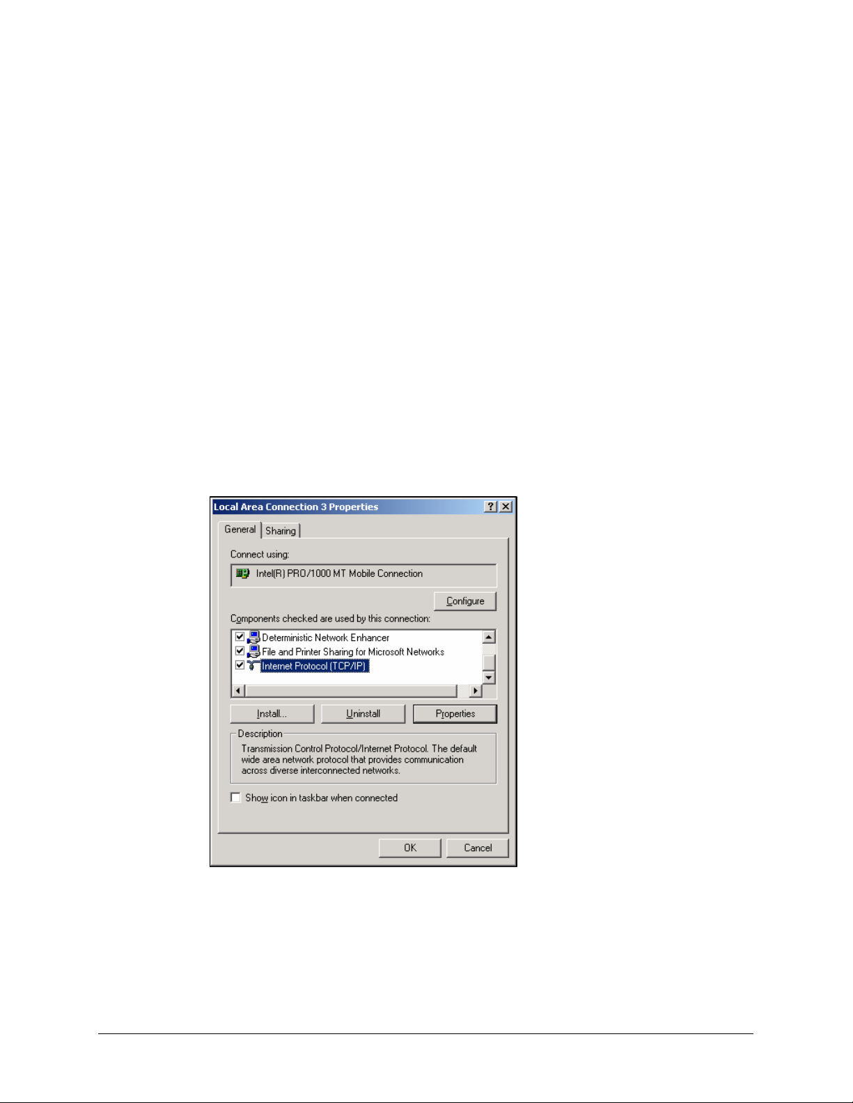
2.
On the [Configuration] tab, select the Internet Protocol (TCP/IP) line for the
applicable Ethernet adapter. Click the [Properties] button.
© SAMSUNG Telecommunications America, L.P.
17
Page 18
Home Page
Table of Contents
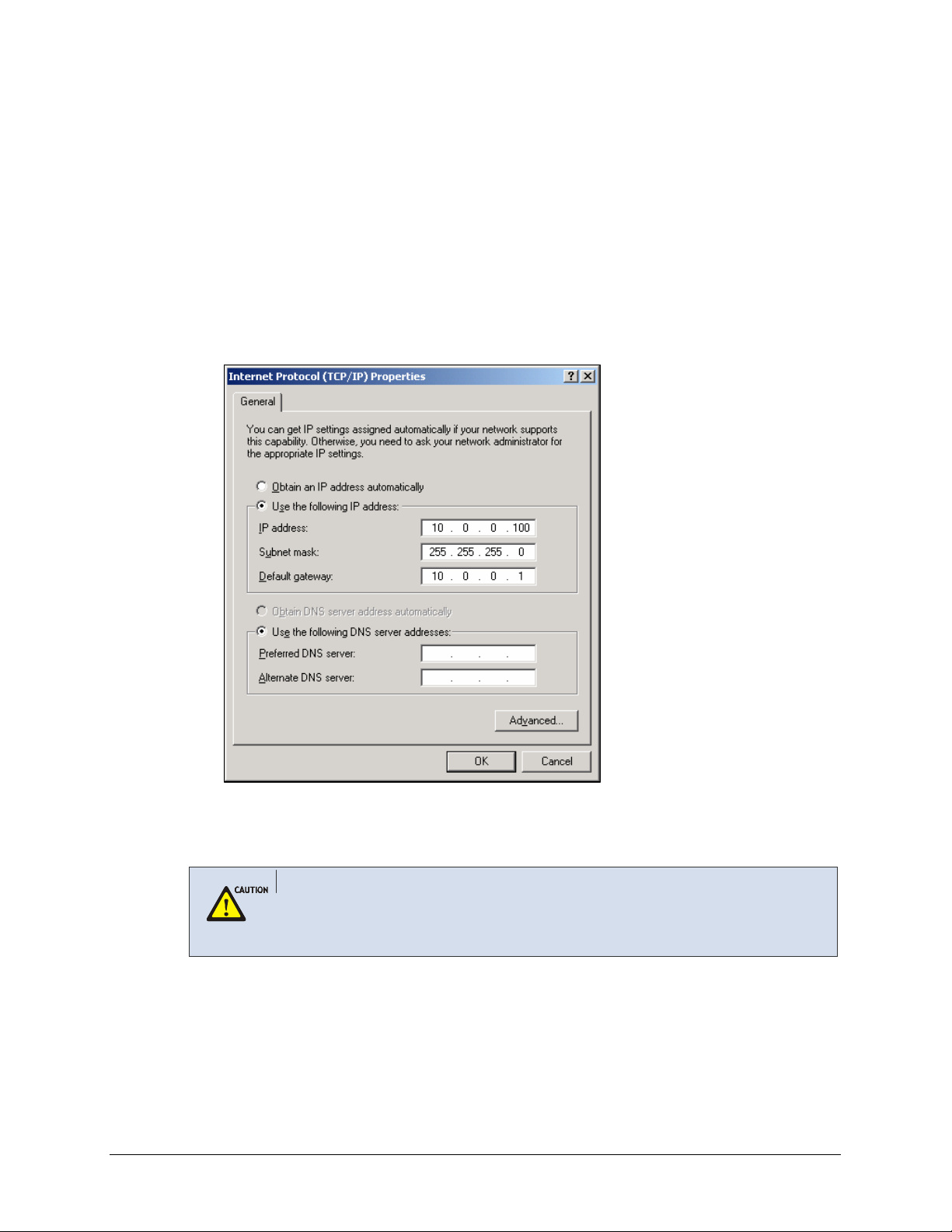
3.
Click the [IP Address] tab and select Specify an IP address. Enter the following IP
address:
• IP Address: Enter a unique IP address that is not used by any other computer on the
network connected to the OS 7200 data server. You can use an IP address in the
ranges of 10.0.0.2 to 10.0.0.254.
• Subnet Mask: 255.255.255.0
• Default Gateway: 10.0.0.1 (OS 7200 Data Server’s default IP address)
Click the [OK] button in the Internet Protocol Properties window. Click the [OK] button
in the Local Area Connection Properties window.
© SAMSUNG Telecommunications America, L.P.
4.
Execute the Internet Explorer from the PC and connect to the IP of LAN. The default IP
address of the WIM board managing the LIM board is set to ‘10.0.0.1’.
Using Web Browser
Use Microsoft Internet Explorer 6.0 or higher as a Web browser to maintain OfficeServ 7200
Data Server.
18
Page 19
Home Page
Table of Contents
Starting up the OfficeServ 7200 Data Server
The procedure for starting up the OfficeServ 7200 Data Server is as follows:
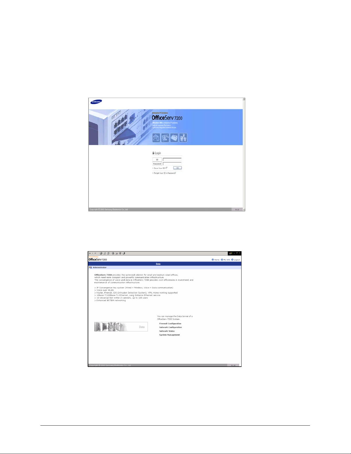
1.
Start the Internet Explorer and enter the IP address of the Data Server into the address
bar. The login window shown below will appear:
2.
Login using the administrator ID and password. The default Login ID and Password are
Admin and Admin respectively. Click the [OK] button to proceed. The following
window will appear:
© SAMSUNG Telecommunications America, L.P.
19
Page 20
Home Page
Table of Contents
3.
Click [Data] to use the menus for Data Server shown in the following window:
When a ‘Data’ menu is selected, the submenus of the Data Server menu appear on the
left section of the window. Descriptions on each submenu are provided in ‘Chapter 3.
Using the OfficeServ 7200 Data Server’.
Delete Temporary Internet Files
Delete Temporary Internet Files after upgrading Data Server package.
Select the [Internet Explorer] Æ [Tools] Æ [Internet Options] menu, click the [Delete Cookies]
and the [Delete Files] button in the [Temporary Internet files].
If the Temporary Internet Files are not cleared, Data Server Web Management displayed info will
not be correct.
© SAMSUNG Telecommunications America, L.P.
20
Page 21
CHAPTER 3. Using the OfficeServ 7200 Data
Home Page
Table of Contents
Server
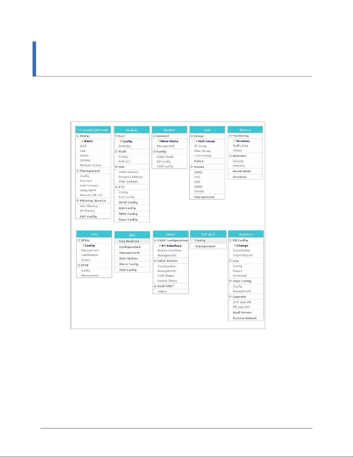
This chapter describes how to use the menus of the OfficeServ 7200 Data Server.
The menus of the OfficeServ 7200 Data Server are as follows:
© SAMSUNG Telecommunications America, L.P.
21
Page 22
Home Page
Table of Contents
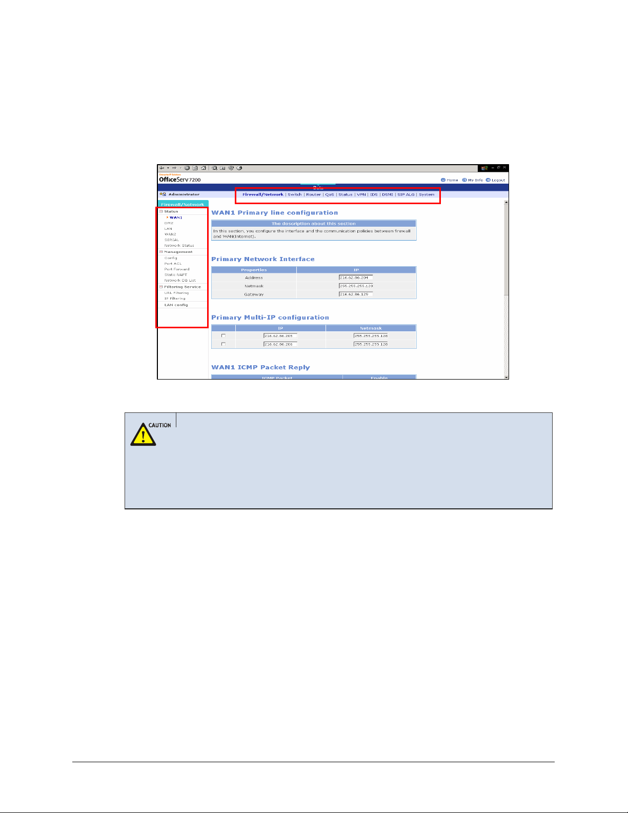
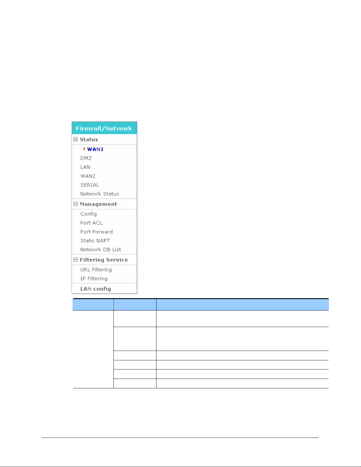
Firewall/Network Menu
Firewall/Network Menu provides a Configuration Wizard to setup the WAN1, WAN2, LAN,
DMZ, and Serial network interfaces, as well as firewall and the communication policies
between the firewall and each interface. Under this menus, you can also setup the Data Server
Access Control List, Port Forward, and Filtering Services.
Select [Firewall/Network] to display the submenus of Firewall/Network on the upper left
section of the window.
© SAMSUNG Telecommunications America, L.P.
Menu Submenu Description
Status
WAN1 Displays user settings of the WAN1 port, which is an external port used for
Internet connection.
DMZ Displays user settings of the DMZ port, which is an internal port. The DMZ
(Demilitarized Zone) allows internal LAN devices to be accessible to
Internet traffic, such as Web servers, FTP servers.
LAN Displays user settings of the LAN port, which is an internal port.
WAN2 Displays user settings of the WAN2 port, which is an external port.
SERIAL Displays user settings of the SERIAL port, which is an external port.
Network status Displays a summary of status of all ports.
22
Page 23

Home Page
Table of Contents
Menu Submenu Description
Management
Service
LAN config - Sets the transfer rate and transmission system of Ethernet port.
Config Sets firewall and network interface configuration.
Port ACL Allows external users to access OS 7200 firewall.
Port Forward Sets port forward to pass thru OS 7200 firewall. The incoming traffic is
directed to specific local PCs based on one specified destination port
number.
Static NAPT Sets port forward to pass thru OS 7200 firewall. The incoming traffic is
directed to specific local PCs based on a range of service port numbers.
Network DB List Deletes DB where settings are saved.
URL Filtering Blocks the internal network web access to the URL name setting. Filtering
IP Filtering Blocks the internal network web access to the IP setting.
© SAMSUNG Telecommunications America, L.P.
23
Page 24
Status
Home Page
Table of Contents
The [Status] menu displays the setting of the WAN1, DMZ, LAN, WAN2, or SERIAL.
Port Setup Procedure
The WAN1, LAN, DMZ, WAN2, and SERIAL ports are set at the [Firewall/Network] Æ
WAN1
The [Status] Æ [WAN1] menu shows the setting of WAN1, which is an external port using a
public IP.
[Management] Æ [Config] menu. Refer to the description on the menu for the setup procedures.
© SAMSUNG Telecommunications America, L.P.
Port Settings
Refer to descriptions on the [Firewall/Network] Æ [Management] Æ [Config] menu for details on
the items of the setting.
24
Page 25
Home Page
Table of Contents
DMZ
LAN
WAN2
SERIAL
The [Status] Æ [DMZ] menu shows the setting of DMZ, which is an internal port using a
private IP or public IP.
The [Status] Æ [LAN] menu shows the setting of LAN, which is an internal port using a
private IP.
The [Status] Æ [WAN2] menu shows the setting of WAN2, which is an external port using a
public IP.
The [Status] Æ [SERIAL] menu shows the setting of SERIAL, which is an external port using
a public IP.
DMZ, LAN, WAN2, and SERIAL ports’ settings
Settings of ports that have no lines connected (When the port is set to ‘Not Used’at the
[Management] Æ [Config] menu) are displayed as ‘No line’s connected to this port’.
© SAMSUNG Telecommunications America, L.P.
25
Page 26
Home Page
Table of Contents
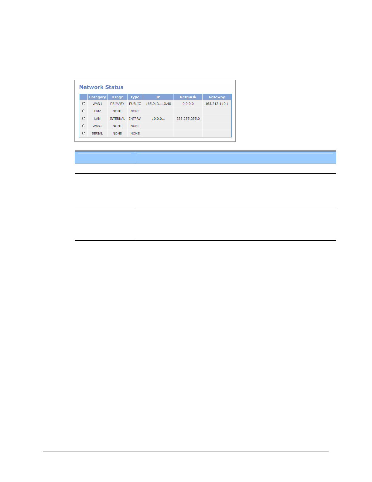
Network Status
The [Status] Æ [Network Status] menu displays the current IP Address of WAN1, DMZ, LAN,
WAN2, and SERIAL.
Category WAN1, DMZ, LAN, WAN2, and SERIAL ports
Usage - NONE: Unused line
Type - NONE: Not used port
Item Description
- PRIMARY: Primary public interface
- SECONDARY: Secondary public interface
- INTERNAL: Line used for internal interface
- PUBLIC: Port using public IP
- INTPRV: Internal port using private IP
- INTDMZ: Internal DMZ port
© SAMSUNG Telecommunications America, L.P.
26
Page 27
g
Home Page
Table of Contents
Management
The [Management] menu sets ports related to firewall and network.
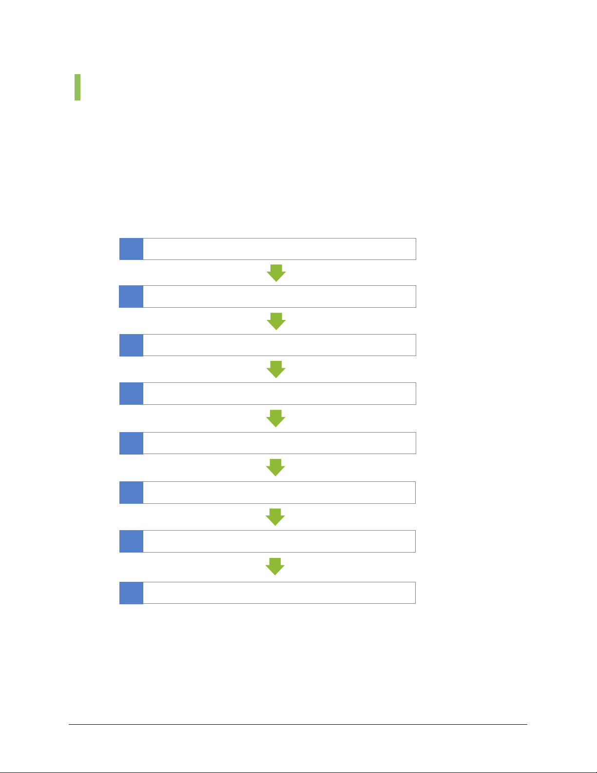
Config
The [Config] menu starts the configuration wizard which will guide through the settings of the
WAN1, LAN, DMZ, WAN2, and SERIAL ports. Select [Management] Æ [Config] and set the
items of each window. Click the [Next] button and set the firewall and network according to
the following procedure:
1
2
3
4
5
6
Initial setup
Configure line type for each port
Configure WAN1
Configure DMZ
Confi
Configure WAN2
ure LAN
© SAMSUNG Telecommunications America, L.P.
7
8
Configure SERIAL
Save settings
27
Page 28
Home Page
Table of Contents
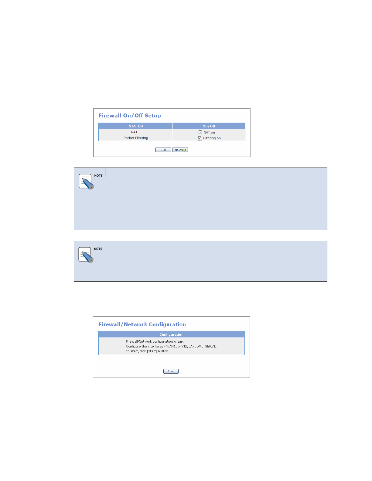
Initial Setup
1.
Select [Management] Æ [Config] and display the window shown below. The ‘NAT’
and ‘Packet Filtering’ items are originally disabled. Check the checkboxes to set the
status to ‘On’ and click the [Run] button.
If these items are checked, Click the [Next] button.
Network Address Translation (NAT)
NAT is an Internet standard that enables a local-area network (LAN) to use one set of IP
addresses for internal traffic and a second set of addresses for external traffic. NAT adds a
level of security by protecting the address of a PC connected to the private LAN from
transmitted on the Internet. If only a single Internet IP address is provided by the ISP
(such as a DSL or cable modems internet account), NAT must be selected to allow all PCs
on the LAN to share this single Internet IP address.
Packet Filtering
2.
Packet Filtering controls access to the local-area network by analyzing the incoming and
outgoing packets and letting them pass or halting them based on the IP address of the
source and destination.
Click the [Start] button to start the Firewall/Network configuration wizard, which will
step through configuration for each interface.
© SAMSUNG Telecommunications America, L.P.
28
Page 29
Home Page
Table of Contents
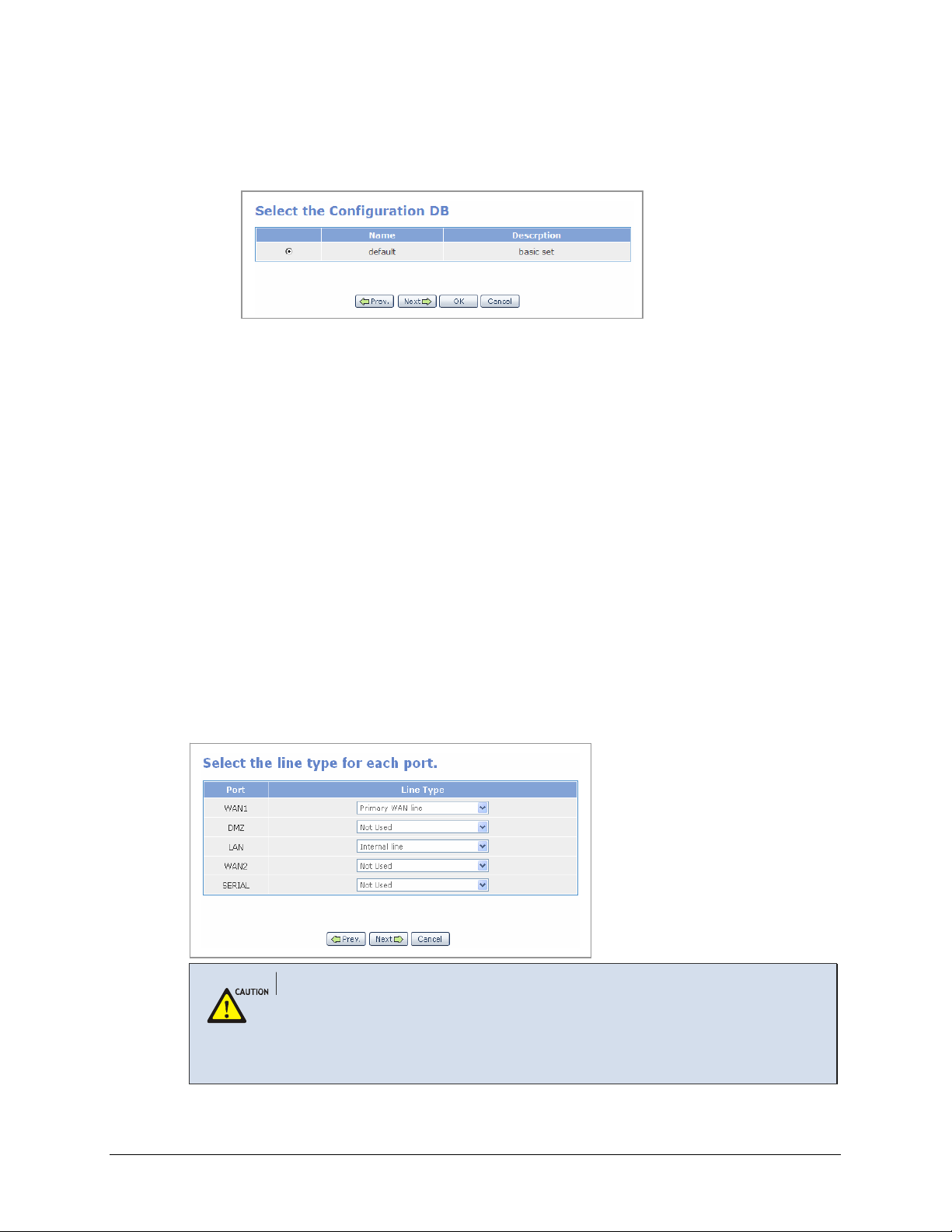
3.
New settings can be set or previously set setup files can be changed or executed from
the following window. The IP of the LAN port is initially set to ‘10.0.0.1’. Check the
‘default’ item and click the [Next] button.
Set Line Type for Each Port
External ports (e.g., WAN1, WAN2, SERIAL) use public IPs while internal ports (e.g., DMZ,
LAN) use public or private IPs. Select the line type for each port as listed below:
• External port (WAN1,WAN2, SERIAL)
o Primary WAN line: Primary internet connection interface
o Secondary WAN line: Secondary internet connection interface
o Third WAN line: Third internet connection interface
o Not Used: No WAN line is connected
• Internal port (DMZ, LAN)
o Internal line: Internal line is used
o Not Used: Internal line is not used
In the figure shown below, WAN1 port is set to Primary WAN line as the primary line, LAN
port is to Internal line as the internal line, and WAN2, SERIAL, and DMZ ports are set to Not
Used as lines not connected:
Dynamic IP Address (e.g. Cable Modem, ADSL PPPoE, and SDSL internet account)
If a dynamically assigned IP address is used for WAN internet connection, information
(e.g., ‘Port Forward’ and ‘Static NAPT’) on public IPs will not be automatically changed.
‘Fixed IP’ should be used for VoIP services that require settings of the ‘Port Forward’ and
‘Static NAPT’ menus and for VPN services that require WAN IP address setting.
© SAMSUNG Telecommunications America, L.P.
29
Page 30
Home Page
Table of Contents
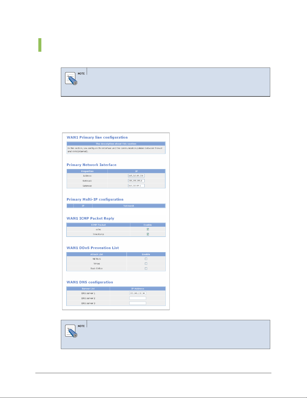
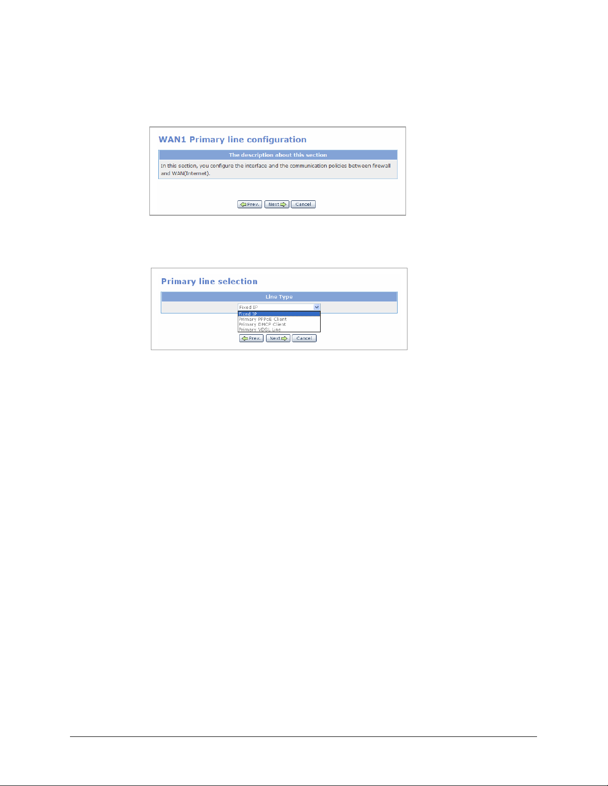
WAN1 Setup
1.
The starting window for setting WAN1 as “Primary WAN line’ is shown below. Click
the [Next] button to start setting the WAN1 port.
2.
Select the line type for Primary WAN line. Select one of the four applications shown
below for the external network:
Fixed IP: Select Fixed IP if your Internet service account uses Fixed IP (Static) IP
assignment.
• Primary PPPoE Client: Select Primary PPPoE Client if your Internet service
account uses PPP over Ethernet login protocol, such as in ADSL account.
• Primary DHCP Client: Select Primary DHCP Client if your Internet service
account uses Dynamic IP assignment, such as in Cable Modem account.
• Primary VDSL Line: Select Primary VDSL Line if your Internet service account
uses VDSL service.
The four applications of Primary WAN line are described below:
a. Fixed IP: Enter values in the Address, Netmask, and Gateway fields to perform
settings in the WAN1 port on an external network where a static IP is used, and
click the [Next] button. To add another IP, apart from the IP of the external line
currently being used, click the [Add] button and add the item. OfficeServ 7200
WAN interface supports up to eight multiple public IP addresses.
© SAMSUNG Telecommunications America, L.P.
30
Page 31

Home Page
Table of Contents
Caution Against Changing Network Interfaces
If a network interface configuration (e.g., IP, gateway, and subnet mask) is changed during router
regular operation, all the active IP sessions that are connected in the router will be disconnected.
b. Primary PPPoE Client: Enter the ID and password to connect an external network
where a dynamic IP will be assigned through PPPoE, and click the [Next] button.
© SAMSUNG Telecommunications America, L.P.
c. Primary DHCP Client: Connect to internet network using a cable modem or a
DHCP server, the port is automatically set. Click the [Next] button and proceed to
the next window.
31
Page 32

Home Page
Table of Contents
PPPoE/DHCP/SDSL Settings
The performance of data uploading or downloading speed depending on Internet Service
Provider services.
d. Primary VDSL line: External network using a VDSL modem.
Enter ‘default’ into the ‘Mac address’ field to disable MAC authentication, and
click the [Next] button. Enter a MAC address into the ‘Mac address’ field to use
the MAC copy function.
MAC Copy Function
When performing authentication through PC MAC of LIM board, MAC of outgoing packets are
copied to PC MAC instead of using MAC of outgoing packets as MAC of WAN1.
3.
Select the items below and clock the [Next] button:
• WAN ICMP Packet Reply: The Internet Control Message Protocol (ICMP) is one
of the core protocols of the Internet protocol suit. ICMP Echo and Timestamp
messages are used for network diagnostics, often to test the availability of a target,
such as the popular ‘ping’ program. Many malicious attacks begin with a ping scan.
Disabling ICMP Packet Reply prevents your system’s discovery with a ping.
OfficeServ 7200 firewall does not respond to ICMP echo and ICMP timestamp by
default. However, if the ‘echo’ and ‘timestamp’ items are checked, response to
external Ping commands will be displayed. If these items are not checked, a
Request timed out will occur to external Ping commands.
• WAN1 DDos prevention: Check the items shown below to prevent DDoS (Denial
of Service) attacks by blocking attacks using the corresponding hacking programs.
© SAMSUNG Telecommunications America, L.P.
32
Page 33

Home Page
Table of Contents
• WAN1 DNS configuration: Enter the IP address of the DNS server. If
PPPoE/DHCP is used, there is no need to manually enter these fields, ISP will
automatically authenticate the DNS servers.
DMZ Setup
1.
The starting window for setting WAN1 as “Primary WAN line’ is shown below. Click
the [Next] button to start setting the WAN1 port.
2.
The starting window for setting DMZ ‘Internal Line’ configuration is shown below.
Click the [Next] button and proceed to start setting the DMZ port.
© SAMSUNG Telecommunications America, L.P.
33
Page 34

Home Page
Table of Contents
3.
Select the line type for the DMZ line. Select one of the three applications shown below
for the DMZ port.
DMZ port supports the following three line type:
a. Internal private network: Use DMZ port as a second private LAN network behind
the router’s firewall.
b. Internal public network: Place DMZ port behind the router in the private network,
but assign it with a public IP address to allow DMZ port accessible from the
public network.
c. DMZ configuration: Configure DMZ port with a private IP address and use the
OfficeServ 7200 NAT router to allow DMZ port accessible from the public
network.
The configurations of each DMZ line type are described below:
• Internal private network: Assign DMZ port with the private IP address in the
Address, and Netmask, fields. If additional private IP addresses with different
subnet are currently being deployed, click the [Add] button to add the items.
OfficeServ 7200 allows up to 4 subnets in the ‘Internal line Multi-IP configuration’.
In the example shown below, two DMZ IP of 192.168.0.1/24 and 192.168.1.1/24
are set.
Under the DMZ shared IP device list, configure the devices from the LAN
interface that can send packets to pass through the DMZ interface and access the
DMZ servers.
© SAMSUNG Telecommunications America, L.P.
34
Page 35

Home Page
Table of Contents
In the example shown below, allow the LAN interface as entered in the ‘Remote
IP’ to access the DMZ servers as entered in the ‘Shared IP’. The Destination Port
of ‘0:’ indicates all ports are allowed for access.
Port Range Setting
- When using ports from 0 to 100, enter ‘0:100’.
- ‘0:’ indicates all ports.
• Internal public network: Assign DMZ port public IP address under the Internal
Line Network Interface and Internal Line Multi-IP Configuration.
In this scenario, the DMZ port with a public IP address is hiding on a private
network behind a router, and still have appearance of being on the public network
‘in front of ‘ the router.
If the checkbox of ‘Internal line Transparent mode configuration’ is selected, the
servers on the DMZ network use the external public IP as the default gateway. If
‘Internal line Transparent mode configuration’ is deactivated, the servers on the
DMZ network use the DMZ port as the default gateway.
© SAMSUNG Telecommunications America, L.P.
35
Page 36

Home Page
Table of Contents
Configure Internal line Public area from WAN for hosts that use DMZ as an
internal public network, and click the [Next] button.
Configure Internal line Public IPs accessible from WAN to allow external
networks to access a specific server on the DMZ network inside the firewall that
has a public IP.
Under the DMZ shared IP device list, configure the devices from the LAN
interface that can send packet to pass through the DMZ firewall and access the
DMZ servers.
• DMZ Configuration: Enter Private IP address values in the Address, and Netmask,
fields. If additional private IP address is currently being deployed, click the [Add]
button to add the items.
In the example shown below, DMZ IP of 192.168.0.1/24 is set.
© SAMSUNG Telecommunications America, L.P.
36
Page 37

Home Page
Table of Contents
Under the Internal line DMZ configuration, configure the servers on the DMZ
network.
Enable port forwarding of a specific packet received through WAN public network
to a host located in DMZ.
• Src IP: Enter the source IP of a packet from public network to be forwarded
to a port.
• Netmask: Enter the netmask of a packet to be forwarded to a port.
• Public IP: Enter the IP address of WAN.
• Private IP: Enter the IP address of a host located in DMZ.
• Service Port: Enter the number of a port to which a packet is forwarded.
• Protocol: Select the type of a protocol to be forwarded.
In the example show below, the following two servers are connected on the DMZ
network:
• Web server with private IP address of 192.168.0.10 and service port of 80
• FTP server with private IP address of 192.168.0.20 and service port of 21
The Source IP address and Netmask are set to 0.0.0.0 to allow all the devices in
the public network to access these two DMZ servers.
Click the [Next] button to move to the next step.
Under the DMZ shared IP device list, configure the devices from the LAN
interface that can send packets to pass through the DMZ and access the DMZ
servers.
In the example shown below, allow the LAN interface as entered in the ‘Remote
IP’ to access the DMZ servers as entered in the ‘Shared IP’. The Destination Port
of ‘0:’ indicates all ports are allowed for access.
© SAMSUNG Telecommunications America, L.P.
37
Page 38

Home Page
Table of Contents
LAN Setup
1.
The below window shows the LAN was set to ‘Internal line’ at the <Select the line type
for each port> window. Click the [Next] button to start LAN port setup.
2.
Select the internal line type.
Types of internal lines are described below:
• Internal private network: Select this option to configure an internal network using a
private IP.
Enter the IP address, Netmask, and Gateway to use LAN as an internal private
network, and click the [Next] button. To add another IP, apart from the IP of the
internal line currently being used, click the [Add] button and add the item.
© SAMSUNG Telecommunications America, L.P.
38
Page 39

Home Page
Table of Contents
Under the LAN shared IP device list, configure the devices from the DMZ
interface that can send packets to pass through the LAN firewall and access the
LAN servers.
Enter the DMZ interface as entered in the ‘Remote IP’ and enter the LAN servers to
be shared in the ‘Shared IP’. The Destination Port of ‘0:’ indicates all ports are
allowed for shared IP Device
• Internal public network: Select this option to configure an internal network using a
public IP. Click [Add] to add an IP in addition to the IPs of the internal line being
used.
If the checkbox of ‘Internal line Transparent mode configuration’ is selected, the
servers on the LAN network use the external public IP as the default gateway. If
‘Internal line Transparent mode configuration’ is deactivated, the servers on the
LAN network use the LAN port as the default gateway.
© SAMSUNG Telecommunications America, L.P.
Configure Internal line Public area from WAN for hosts that use LAN as an
internal public network, and click the [Next] button.
39
Page 40

Home Page
Table of Contents
Configure Internal line Public IPs accessible from WAN to allow external
networks to access a specific server on the LAN network inside the firewall that has
a public IP.
Under the LAN shared IP device list, configure the devices from the DMZ
interface that can send packets to pass through the LAN firewall and access the
LAN servers.
Enter the DMZ interface as entered in the ‘Remote IP’ and enter the LAN servers to
be shared in the ‘Shared IP’. The Destination Port of ‘0:’ indicates all ports are
allowed for shared IP Device
• DMZ configuration: Enter Private IP address values in the Address and Netmask
fields. If additional private IP address is currently being deployed, click the [Add]
button to add the items.
© SAMSUNG Telecommunications America, L.P.
40
Page 41

Home Page
Table of Contents
In the example shown below, LAN IP of 10.0.0.1/24 is set.
Under the Internal line DMZ configuration, configure the servers on the LAN
network. Enable port forwarding of a specific packet received through WAN to a
host located in LAN.
• Src IP: Enter the source IP of a packet to be forwarded to a port.
• Netmask: Enter the netmask of a packet to be forwarded to a port.
• Public IP: Enter the IP address of WAN.
• Private IP: Enter the IP address of a host located in DMZ.
• Service Port: Enter the number of a port to which a packet is forwarded.
• Protocol: Select the type of a protocol to be forwarded.
The following window illustrates an example of forwarding all packets (Src IP:
0.0.0.0, Network: 0.0.0.0, Service Port: 0, Protocol: all) that enters the WAN
Interface IP (211.217.172.200) to a host (192.168.1.100) located in DMZ:
© SAMSUNG Telecommunications America, L.P.
Under the LAN shared IP device list, configure the devices from the DMZ interface
that can send packets to pass through the LAN and access the servers inside the
LAN port. Click the [Next] button.
41
Page 42

Home Page
Table of Contents
WAN2 Setup
1.
If WAN2 was set to Primary WAN line, secondary WAN line, or Third WAN line, click
[Next] button to proceed with the WAN2 Setup procedures.
2.
Follow the same setup procedures as described in WAN1 setup procedures.
3.
Configure WAN2 Outbound traffic configuration to specify packets that could be
sent from LAN or DMZ interfaces via WAN2 interface.
4.
Configure WAN2 Exceptional outbound traffic configuration to specify packets that
are sent from LAN or DMZ interface to be restricted from WAN2 interface.
© SAMSUNG Telecommunications America, L.P.
42
Page 43

Home Page
Table of Contents
SERIAL Setup
The below window shows that SERIAL was set to ‘No line’ at the <Select the line type for
each port> window (Refer to ‘Set Line Type for Each Port’).
Click the [Next] button and proceed to the next window.
Follow the procedure below to use SERIAL as the Primary WAN line:
1.
Set the SERIAL to ‘Primary WAN line’ at the <Select the line type for each port>
window (Refer to ‘Set Line Type for Each Port’), and click the [Next] button.
2.
Click the [Next] button to start the SERIAL port setup.
3.
Select the type of the Primary line.
© SAMSUNG Telecommunications America, L.P.
43
Page 44

Home Page
Table of Contents
• Primary CISCO: Select ‘Primary CISCO’ from the <Primary line selection> window
and click the [Next] button to display the window shown below. Enter the items and
click the [Next] button. The CISCO method refers to the HDLC supported by Cisco.
• Primary PPP: Select ‘Primary PPP’ from the <Primary line selection> window and
click the [Next] button to display the window shown below. Enter the address,
netmask, and point-to-point items.
Select the authentication protocols: None, PAP, or CHAP. Then set the user name
and password for the remote router connecting to the router. Click the [Next] button.
© SAMSUNG Telecommunications America, L.P.
If the Primary PPP-Authentication item is set to ‘NONE’, do not enter the ID and
password.
44
Page 45

Home Page
Table of Contents
• Primary Frame Relay: Select ‘Primary Frame Relay’ from the <Primary line
selection> window and click the [Next] button to display the window shown below.
Enter the items in the Primary SERIAL Network Interface (Frame Relay) and
Primary Additional Configuration menus. These values must match the
corresponding values set in the frame relay service provider’s switch.
Click the [Next] button.
Item Description
LMI TYPE [ansi,
ccitt, none]
create[16~999] Range 16~999
T391[5~30,10 sec] Range 5~30, default is 10 sec.
N391[1~255,6] Range 1~255, default is 6.
N392[1~10,3] Range 1~10, default is 3.
Local Management Interface, a signaling standard between the router
and the frame relay switch it is connected to. OfficeServ 7200 supports
two LMI standards:
- ansi: ANSI T1.617 Annex D
- ccitt: CCITT
Signaling channel No.
OfficeServ 7200 supports one Permanent Virtual Circuit (PVC).
Link Integrity Verification Timer (in seconds). Time interval for DTE to
send KeepAlive message.
Full Status Polling Verification Timer counter, which means the cycle of
requesting information on full status based on the number of times that
KeepAlive is sent.
Error threshold counter, the limit of number of repeated errors before the
link is marked inactive.
© SAMSUNG Telecommunications America, L.P.
45
Page 46

Home Page
Table of Contents
Item Description
N393[1~10,4] Range 1~10, default is 4.
Monitored Events Counter. When a network becomes active, the
number of successful exchanges of KeepAlive messages before the link
is considered active.
Saving Settings
1.
The below window shows the firewall and network setup is complete. Click the [Next]
button and proceed to the next window.
2.
Enter values in the Name and Description fields and click the [Next] button to save the
settings in the database. Only uppercase and lowercase alphabet and numbers can be
entered in the ‘Name’ field. Special characters cannot be entered, and ‘default’ is not
available.
© SAMSUNG Telecommunications America, L.P.
3.
Click the [Save] button to save the setting as a file having the file name set above. Click
the [OK] button to run the settings upon saving, or click the [Cancel] button the cancel
the setting.
46
Page 47

Home Page
Table of Contents
Port ACL
If ‘Packet Filtering’ in ‘Firewall On/Off Setup’ is set to ‘Filtering on’ under [Management] Æ
[Config], external users can not access the OfficeServ 7200 firewall. The [Port ACL] menu is
used to allow a specific external IP to access the firewall.
Select [Management] Æ [Port ACL] and set the IP address, port, and protocol, as shown below,
and click the [OK] button:
If the user sets the options as shown above, the server whose IP address is ‘211.217.127.33’
can connect to the system firewall via the web. The external servers can also connect to the
firewall by using connection programs such as Telnet and SSH.
Security Warning
Note that all external users are allowed to access the firewall when the Remote IP is set to
‘0.0.0.0’ and Port is set to ‘0:’.
© SAMSUNG Telecommunications America, L.P.
47
Page 48

Home Page
Table of Contents
Port Forward
The [Port Forward] menu is used to forward packets so that services of the internal server
connected to the firewall can be used externally.
For instance, assume that an internal server uses the public IP of the firewall as
‘211.217.127.70’ and the private IP as ‘10.0.0.100’. If the user uses the telnet server inside the
firewall from a server on a network outside the firewall, the user can use telnet services using
the Port Forward setting.
Click the [Add] button, and enter values as shown in the above figure. Then, access the telnet
server from a network outside the firewall by setting the public IP address to ‘211.217.127.70’
to use telnet services inside the firewall (10.0.0.100).
• Public IP: Public IP of the firewall
• Internal IP: Private IP of the internal server connected to the firewall
• Port: Port No. of the service (e.g., Port of the telnet server)
• Protocol: Select a protocol from all/tcp/udp.
Specifying a Range of Port
Use the Static NAPT menu if a range of port needs to be specified.
© SAMSUNG Telecommunications America, L.P.
48
Page 49

Home Page
Table of Contents
Static NAPT
The ‘Static NAPT list’ window displays the settings of the [Static NAPT] menu.
Also, this window displays the ‘VoIP NAPT’ setting in the DSMI menu as well as the user
setting of the ‘Static NAPT’ menu.
Click the [Edit] button to switch to a window where the user can enter the settings of Static
NAPT.
Network DB List
The [DB List] menu is used to delete the settings file saved in the [Management] Æ [Config]
menu.
© SAMSUNG Telecommunications America, L.P.
49
Page 50

Home Page
Table of Contents
Filtering Service
The [Filtering Service] menu is used to block the internal local area network users from
accessing to a specific URL or IP locations on the Internet.
URL Filtering
The [URL Filtering] menu is used to block access to a specific URL from an internal host or
network.
• SrcIP: An internal host or network where filtering will be performed. Enter the IP address
to filter URLs from each host and the network address to filter URLs from each network.
• Netmask: Set Netmask to ‘255.255.255.255’ in order to filter URLs from each host. Enter
the subnet of the network to filter URLs from each network.
• URL: Name of a site (Domain) to be blocked
The figure below illustrates an example of blocking access to ‘yahoo’ by all internal users.
Enter values as shown in the figure below and click the [OK] button to complete the settings.
© SAMSUNG Telecommunications America, L.P.
50
Page 51

Home Page
Table of Contents
IP Filtering
The [IP Filtering] menu is used to block access to a specific service of an external IP by
internal users. Enter the IP address and netmask in the ‘Src IP’ and ‘Netmask’ fields, and
information on a specific service of the external network to which access will be blocked in
the ‘Dest IP’, ‘Netmask’, ‘Dest Port’, and ‘Protocol’ fields.
If the user enters the network IP and subnet in the Src IP and Netmask fields, the user can
enable filtering of an entire network.
Click the [Add] button, and enter values as shown in the above figure. Click the [OK] button.
Then, any terminals cannot access Ports 80 and 22 whose destination address is
‘211.17.127.70’.
© SAMSUNG Telecommunications America, L.P.
51
Page 52

Home Page
Table of Contents
LAN Config
The [LAN Config] menu sets the negotiation, speed, and transfer system for each port.
Select the checkbox of the port to set and click [OK].
Click [Default] to reset to the default value.
Negotiation - auto: Controls speed through negotiation.
Speed (Mbps) Transfer rate of port
Duplex - full: Bi-directional service (full-duplex system)
Item Description
- force: Controls speed through enforcement.
Set this item to ‘force’ when setting the Duplex item to ‘full’.
- half: Unidirectional service (half-duplex system)
Setting for the WAN2 10 M interface depends on the counterpart
modem.
© SAMSUNG Telecommunications America, L.P.
52
Page 53

Home Page
Table of Contents
Switch Menus
Select [Switch] to display the submenus of Switch on the upper left section of the window.
Menu Submenu Description
Config Sets the switch port environment. Port
Statistics Displays the link status, speed, transmission system, and statistics of the
switch port.
Config Configures Virtual LAN(VLAN). VLAN
Port VID Sets processing method for untagged packets when VLAN mode is set to
‘Tag-based VLAN’.
MAC
STP
IGMP Config - Efficiently processes multicast packets through IGMP snooping.
Static Address Saves MAC address to the static address table of the switch.
Dynamic Address Retrieves the dynamic address table or deletes a MAC address.
Filter Address Enters the MAC address to block the frame data with the MAC address
information identical with the entered value from the switch.
Config Prevents broadcast storming due to the switch loop-back using the STP
function.
Port Config Retrieve the STP status of each port. Enters the new Path Cost and Port
Priority values for each port.
© SAMSUNG Telecommunications America, L.P.
53
Page 54

Home Page
Table of Contents
Port
Config
(Continued)
Menu Submenu Description
QoS Config - Processes Quality of Service by sequentially assigning priority to packets
entering the switch or by enforcing priority on a specific port.
MISC Config - Sets mirroring and other switching functions.
Save Config - Saves setting to flash disk or initializes all setting values.
The [Port] menu is used for setting port related functions and retrieving information on a port.
Select [Port] Æ [Config] to set the environment of a switch port.
© SAMSUNG Telecommunications America, L.P.
54
Page 55

Home Page
Table of Contents
Item Description
Port Manage 16 10/100MB Ethernet switch ports
Select All to process all ports simultaneously.
Active Use to activate and de-active the port.
Negotiation - Auto: Controls speed through negotiation.
- Force: Controls speed through enforcement. Set this item to ‘force’ when Full Duplex is
selected for Speed.
- Nway Force
Speed/Dpx - Speed: By default the speed is set according to the value set in ‘Path Cost’ of the [Switch] Æ
[STP] Æ [Port Config] menu. 10 Mb/s when ‘Path Cost’ is set to ‘100’, and 100 Mb/s when set
to ‘19’.
If the port has been set to auto-negotiation mode, the local ports will automatically negotiate
the port speed.
- Dpx(Duplex):
Full: Set the port to full duplex to send and receive data packets at the same time for bi-
directional service.
Half: Set the port to half-duplex to either send or receive only for the unidirectional service.
If the port has been set to auto-negotiation mode, the local ports will automatically negotiate
the duplex mode.
Flow Ctl Enable or disable the flow control function. Flow control is performed according to the value
set for Rate (%) In/Out (incoming rate/outgoing rate). Limiting the rate at which a port can
receive or send traffic is used to ease congestion on bottlenecks in the network and provide
simple prioritization when the network is busy.
Rate (%)
In/Out
Security Enable or disable the MAC address security check function. This Security check function
Priority Set the priority of each port to ‘Off’, ‘High’ or ‘Low’. Traffic prioritization allows high priority data,
Flow can be controlled by setting the incoming and outgoing rate in percentage for each port.
The unit is the ratio against port speed, and should be set to ‘0’ when flow control item is not
checked.
allows the system to prevent any unauthorized terminal to be connected to the port based on
the MAC address.
- Disable: System default value, system will not perform MAC address check function.
- Enable: If the switch port where ‘Security’ is checked, only the terminal with the MAC address
registered under [Switch] -> [MAC] -> [Static Address] could be connected. Thus, the
unauthorized terminal whose MAC address not entered in the Static MAC address
connecting to the switch will be block.
such as time-sensitive and system-critical data to be transferred without being delayed by
lower priority data. This field is only valid if the QoS Mode setting under [Switch] Æ [QoS
Config] Æ [QoS Configuration] menu is set to <All High before Low> or <Weighted Round
Robin>.
- Off: no priority is set
- ‘Low’ or ‘High’: The priority is set to ‘Low’ or ‘High’, regardless of the QoS bit settings of the
packet received by the port.
© SAMSUNG Telecommunications America, L.P.
55
Page 56

Home Page
Table of Contents
Statistics
The [Port] Æ [Statistics] menu provides a summary of the current switch’s status, including link
status, speed, transmission system, and statistics. The numbers show the accumulated values for
the period from the system boot up to date. The window is automatically updated every five
seconds. Click the [Reset] button to initialize all values to ‘0’.
• TxGdPkt: The number of packets which are successfully sent to the port
• TxBdPkt: The number of packets which are switched, but not successfully transmitted to
the port.
• RxGdPkt: The number of packets which are successfully received by the port.
• RxBdPkt: The number of packets which are successfully received by the port, but not
successfully switched.
• Collision: The number of collision occurred between packets received from the port and
the switched packets
• DropPkt: The number of packets which are not switched to the port, but are dumped in the buffer.
© SAMSUNG Telecommunications America, L.P.
56
Page 57

Home Page
Table of Contents
VLAN
Config
The [VLAN] menu is used for configuring Virtual LAN(VLAN).
A Virtual LAN (VLAN) is a logical network grouping that provide separation of broadcast
domains and functional work area to improve performance. Basically, creating a VLAN from a
switch is logically equivalent of reconnecting a group of network device to another Layer 2
switch. However, all the network devices are still plug into the same switch physically.
OfficeServ 7200 managed switch supports the following VLAN configurations:
• MAC Based
• 802.1Q Tag Based
• Port Based
In the default configuration, VLAN support is disabled.
Select [VLAN] Æ [Config] to display the VLAN configuration window.
Select a VLAN mode from the ‘VLAN Operation Mode’ and click the [OK] button. Then,
enter a VLAN name and ID and click the [Add] button to add the VLAN.
Check a VLAN and click the [Delete] button to delete the VLAN.
VLAN configuration is determined according to the three VLAN modes below:
• Port Based VLAN
• Tag Based VLAN(802.1 Q)
• MAC Based VLAN
Port Based VLAN
This option is used to configure VLAN on port basis. Packets can only be broadcast among
members of the same VLAN group. A single port can be assigned to multiple VLANs. All
unselected ports are treated as belonging to another single VLAN. If the port-based VLAN
enabled, the VLAN-tagging is ignored.
© SAMSUNG Telecommunications America, L.P.
57
Page 58

Home Page
Table of Contents
Select ‘Port Based’ as the VLAN Operation Mode from the <VLAN Configuration> window.
Select a VLAN and click the [Edit] button to display the window shown below. Select the
target port at VLAN Members and click the [Save] button.
Inter-VLAN Communication
To perform communication between VLANs, enable the Inter-VLAN service. If the devices
placed in a VLAN need to communicate with devices in a different VLAN, a shared port with
connections to both VLANs needs to be present. OfficeServ 7200 WIM router will provide the
the inter VLAN communication as it has an IP interface on each VLAN.
Thus if the WIM and LIM are connected through the backbone, the inter-VLAN
communication will use that physical port as the shared port.
On the other hand, if the jumper pin of the WIM board is set toward the front side of the board,
the port on the LIM that is used to connect with the LAN port of the WIM board, should be set
as a VLAN member.
Tag Based VLAN (802.1 Q)
Tag-based VLAN is an IEEE 802.1Q specification standard. IEEE 802.1Q VLAN uses a
technique to insert a ‘tag’ into the Ethernet Frames. Tag contains a VLAN Identifier (VID) that
indicates the VLAN numbers. Enable 802.1Q VLAN, all ports on the switch belong to default
VID of 1. OfficeServ 7200 supports up to 256 tag-based VLAN groups.
© SAMSUNG Telecommunications America, L.P.
58
Page 59

Home Page
Table of Contents
Packets not including tags are delivered to a single VLAN and its VLAN ID is defined in the
menu [VLAN] -> [Port VID].
Tag Based VLAN is composed of tagged members and untagged members. This determines
whether or not the system will remove (untag) tags before sending traffic out of each port.
Select ‘Tag Based’ as the VLAN Operation Mode from the <VLAN Configuration> window
1. Type a name for the new VLAN.
2. Type a VID (between
3. Click the [Edit] button to display the window shown below.
4. Select the protocol type. OS 7200 support 802.1v with the implementation of Port-and-
Protocol- based VLAN classification. User can combine the field ‘Protocol VLAN’ and
the field of the port member to form a new VLAN group.
5. Select the ports to set the outgoing frames for VLAN-Tagged frame or no.
o VLAN Untagged Members: outgoing frame without VLAN-Tagged
o VLAN Tagged Members: outgoing frames with VLAN-Tagged.
6. Click the [Save].
• VLAN Untagged Members: If one of ports(1~16) is determined for switching and
transmission, select a port for delivering the Ethernet frame from which the tag
information is deleted.
• VLAN Tagged Members: If one of ports(1~16) is determined for switching and
transmission, select a port for storing and sending the tag information. Connect the IEEE
802.1Q-supported terminal to the selected port.
© SAMSUNG Telecommunications America, L.P.
59
Page 60

Home Page
Table of Contents
MAC Based VLAN
Membership in MAC Based VLAN is based on assigning the MAC address of a device to a
VLAN. VLAN is configured without information on port and the number of a VLAN member
may change. The advantage of MAC based VLAN is that even if users relocate, they remain
on the same VLAN as long as they stay connected to the same switch. Up to 1024 MAC
members can be saved either in a single VLAN or in multiple VLANs.
Since a MAC Based VLAN does not basically contain port information, the port serves as a
VLAN member by receiving Address Resolution Protocol(ARP). Thus, the ARP packet must
be transmitted to the switch to enable members of a VLAN to exchange packets.
Select ‘MAC Based VLAN’ as the VLAN Operation Mode from the <VLAN Configuration>
window and click the target VLAN, and click the [Edit] button to display the window shown
below. Enter the MAC address of a member into the ‘Add’ field and click the [Add] button to
add the member or click the [Delete] button to delete the member.
© SAMSUNG Telecommunications America, L.P.
60
Page 61

Home Page
Table of Contents
Port VID
If the VLAN mode is ‘Tag-based VLAN’, the Port VID is set at the [VLAN] Æ [Port VID]
menu to determine the processing system for untagged packets. This feature is useful for
accommodating devices that you want to participate in the VLAN but they don’t support
tagging. OS 7200 switch allows user to set one PVID for each port, the range is 1 to 255 with
default PVID of 1. The PVID must be the same as the VLAN ID that port belongs to in the
VLAN group, or the untagged traffic will be dropped.
Item Description
Port VID
Forward Only this Vlan Selected: forward only the packet with VID matching this
Drop Untagged Frame Selected: drop the untagged packet.
VLAN ID for untagged packets, value between 1 and 255.
Default Port VID is 1.
If the Untagged packet is received by the port, the packet is
switched to VLAN identical to Port VID.
port’s configured VID.
Not selected: the packet is retransmitted according to the
received Tag information.
Not selected: retransmit untagged packets only to VLAN
corresponding to the designated Port VID.
VID Setting
In a mode where the 802.1Q VLAN is set, enter the ‘VLAN ID’ value when entering settings in
the ‘Static Address’, ‘Filter Address’ menu. If the value is not entered, ‘0’ is set.
© SAMSUNG Telecommunications America, L.P.
61
Page 62

Home Page
Table of Contents
MAC
The [MAC] menu is used for retrieving the address table of the switch or for setting Filtering
MAC.
Static Address
Select [MAC] Æ [Static Address] to save a MAC address to the address table of a switch
regardless of whether the device and switch is physically connected to the switch. This saves
the switch from having to re-learn a device’s MAC address when the disconnected or
powered-off device is active on the network again.
Enter the MAC address and port No., and click the [Add] button.
Select a MAC address and click the [Delete] button to delete the address.
If Security of the port is set in the [Port] Æ [Config] menu, the learning for the source MAC
address is not performed. In this case, since the Static MAC address set in the port is allowed
to access the port, it is possible to set the security function using it.
Number of Static MAC Address Input
Regardless of port, you can enter 50 Static MAC Addresses in total.
© SAMSUNG Telecommunications America, L.P.
62
Page 63

Home Page
Table of Contents
Dynamic Address
Select [MAC] Æ [Dynamic Address] to retrieve the current MAC adress that the switch has
learned.
Select a MAC address and click the [Delete] button to delete the address.
Filter Address
MAC address filtering allows the switch to drop unwanted traffic. Traffic is filtered based on
the destination addresses. Select the [Filter Address] menu and enter a MAC address to block
the corresponding packet from the switch. The MAC address is the destination address of a
packet entering the switch port.
Enter the MAC address and port No. and click the [Add] button.
Select a MAC address and click the [Delete] button to delete the address.
© SAMSUNG Telecommunications America, L.P.
63
Page 64

Home Page
Table of Contents
STP
Config
The [STP] menu is used to set the Spanning Tree Protocol (STP) function or to retrieve STP
status.
The Spanning Tree Protocol is a standardized method (IEEE 802.1D) to provide path
redundancy while preventing endless loops of traffic in switched network. Loops occur when
there are alternate routes between hosts.
• To establish path redundancy, STP creates a tree that spans all of the switches in a network,
forcing redundant paths into a standby state.
• STP allows only one active path at a time between any two network devices but
establishes the redundant links as a backup if the initial link should fails.
• If STP costs change, or if one network segment in the STP becomes unreachable, STP
reconfigures the spanning tree topology and re-establishes the link by activating the
standby path.
Select [STP] Æ [Config] to set STP and to prevent switch loop-back.
Item Description
STP Mode Disable or enable STP. STP is disabled by default.
Priority Set priority for deactivating ports in case switch loop-back occurs. The
priority is used to identify the root bridge. Bridge with the lowest value
has the highest priority and is selected as the root. Enter a number 1
through 65535.
Forward Delay Forward delay time, set number of seconds a port waits before
changing from its STP configuration messages. Enter a number 4
through 30.
Hello Time Set the transmission interval for STP set messages. Enter a number 1
through 10.
Max Age Time Set the number of second bridge waits without receiving STP
configuration before attempting a reconfiguration. Enter a number 6
through 40.
© SAMSUNG Telecommunications America, L.P.
64
Page 65

Home Page
Table of Contents
Port Config
Select [STP] Æ [Port Config] to set or retrieve STP status.
Item Description
Port 16 switch ports are equipped in all.
Select All to process all ports simultaneously.
Path Cost Set the path cost of the port that switch uses to determine which port are
the forwarding ports. The port with the lowest number will be selected as
the forwarding port.
Set to ‘100’ for 10 Mb/s, and to ‘19’ for 100 Mb/s.
The ‘Speed’ value of the ‘Speed/Dpx’ item at the [Switch] Æ [Port] Æ
[Config] menu is automatically set according to the setting of this item.
Port Priority Set priority for deactivating ports in case switch loop-back occurs. The
default setting is 128. Note: The lowest number has the highest priority.
State Indicates the status of each port.
- blocking: If a loop occurs on the switch, the corresponding port is
blocked and data is no longer sent to the port.
- listening: The port is learning the path to the Root Bridge, and can
transmit/receive BPDU (Bridge Protocol Data Units, frames which carry
the spanning tree protocol information). However, the port cannot send
data nor update the MAC address table. This status continues for the
time length set in the ‘Forward Delay’ item of the <STP Configuration>
window.
- learning: Similar to ‘listening’, but can exchange BPDU and update the
MAC address table. However, data cannot be sent. This status
continues for the time length set in the ‘Forward Delay’ item of the
<STP Configuration> window.
- forwarding: Normal communication is enabled.
© SAMSUNG Telecommunications America, L.P.
65
Page 66

Home Page
Table of Contents
IGMP Config
The [IGMP Config] menu is used to efficiently process multicast packets through Internet
Group Management Protocol(IGMP) snooping. IGMP is the standard for IP multicasting in the
Internet. It is used to establish host membership in particular multicast groups on a single
network. IGMP allows a host to inform its local router, using Host Membership Reports,
which it wants to receive messages addressed to a specific multicast group.
Without IGMP snooping, multicast traffic is treated in the same manner as broadcast traffic,
forwarded to all ports. With IGMP snooping, multicast traffic of a group is only forwarded to
ports that have members of that group. IGMP Snooping generates no additional network traffic,
allowing a significantly reduced multicast traffic passing through the switch.
Item Description
IGMP Mode Set whether to perform multicasting through IGMP snooping. If the
IGMP snooping is not used, the received multicasting packet is
broadcasted. By default, IGMP is disabled.
Cross VLAN If this item is set, it is possible to transmit a packet between
different VLANs when the multicasting packet reaches the switch.
Immediate Leave Set this item to delete a member from the multicast table upon
receiving the IGMPv2 Leave message. This also enables
information to be quickly applied to the multicast table when the
hosts are directly connected to the switch ports.
© SAMSUNG Telecommunications America, L.P.
66
Page 67

Home Page
Table of Contents
QoS Config
The [QoS Config] menu is used for processing QoS by sequentially assigning priority to
packets entering the switch or by enforcing priority on a specific port. OfficeServ 7200
managed switch provides Layer 2 QoS functionality to better prioritize and manage packets.
QoS Mode Select the QoS mode.
Weight If the user wants to use a ‘Weighted Round Robin’ method, set the ratio of high weight to
Delay Bound/
Max Delay Time
High Priority Levels Assign the CoS values for the High Priority Levels queue.
Item Description
- First Come First Service: The sequence of packets sent is depending on arrive orders.
(QoS is not used.)
- All High before Low: Packets with higher priority are sent ahead of those with lower
priority. Packets with a low priority are not transmitted until packets with a high priority
are transmitted.
- Weighted Round Robin: Packets with a high priority and packets with a low priority are
transmitted according to the fixed weight. For example, setting High weight to ‘5’ and
Low weight to ‘2’ will send five higher priority packets before sending two lower priority
packets.
low weight.
Limit the low priority packets queuing time in switch when the QoS mode is ‘All High
before Low’ or ‘Weighted Round Robin’. The unit of ‘Max Delay Time’ is ms (1/1000 sec)
and the initial value is 255 ms. If the low priority packet stays in switch exceed Max
Delay Time, the packet will be sent. The valid range is 1 to 255ms.
OfficeServ 7200 LIM switch supports 2 output queues, High and Low. Each queue can
be assigned using 802.1p CoS values. 802.1p CoS operates at Layer 2 of the OSI
model, and values range from 0 to 7 with 0 being lowest priority. CoS values of level 4 -7
are assigned to High Priority Queue by default.
© SAMSUNG Telecommunications America, L.P.
67
Page 68

Home Page
Table of Contents
MISC Config
The [MISC Config] menu is used for setting the mirroring function and other switching
functions.
Port Mirror
The Port Mirror is a method for monitoring traffic in switched networks. Traffic through ports
can be monitored by one specific port. That is all traffic goes in or out of the monitored port
will be duplicated into mirror port.
Broadcast Storm Filter
To configure broadcast storm control, enable the broadcast storm filter and set the upper
threshold for the individual ports. The threshold is the percentage of the port’s total bandwidth
used by broadcast traffic. When the broadcast traffic for a port rises above the threshold,
broadcast storm control becomes active. The valid threshold value is 5%, 10%, 15%, 20%,
25%, and off.
Item Description
Mode Set whether to use mirroring.
Monitoring Port Set the port performing monitoring. Generally, it means
Monitored Port Set the target port of monitoring. All monitor traffic will be
© SAMSUNG Telecommunications America, L.P.
- Off: Do not use mirroring
- Tx: Use mirroring for Tx packets
- Rx: Use mirroring for Rx packets
- Both: Use mirroring for Tx and Rx packets
the connection port of a PC for monitoring.
copied to mirror port. A maximum of 16 monitor ports can
be selected. User can choose which port that they want
to monitor in only one mirror mode.
68
Page 69

Home Page
Table of Contents
Item Description
MAC Age-Out
Delay Bound
Max Bridge Transmit
Delay Bound
Broadcast Storm
Filter Mode
Save Config
Set the time during which an updated MAC
address(Learning) may remain in the address table.
Default value is 300 sec.
In case of the unmanaged LIM that is not controlled by
WIM, if the LAN port is disconnected, the updated MAC
address is automatically deleted in 300 seconds.
Therefore, the new MAC address is not updated
immediately when the LAN port is connected again.
In case of the managed LIM(installed into Slot 2)
controlled by WIM, if the LAN port is disconnected, the
updated MAC address is deleted automatically and
immediately. The new MAC address and MAC address
table are updated at a fast speed when the LAN port is
connected again.
Set maximum packet waiting time to Off, 1 sec, 2 sec , or
4 sec.
Set among 5, 10, 15, 20, 25 % of the total buffer size.
Broadcast packets exceeding this value are lost.
The [Save Config] menu is used to save settings to the flash disk. Since settings are basically
saved in RAM, the settings will be lost when system is turned off. The settings are saved in the
flash disk to prevent the data from being erased during rebooting.
Item Description
Save Current Configuration Saves current setting to flash disk.
If the system is rebooted without saving the setting, the
setting will be lost and will not be applied to the system.
Save Default Configuration Changes settings in the flash disk to default values.
Default values are applied after system rebooting.
Saving or Importing the Switch DB
Click [System] Æ [DB Config] Æ [Save/Delete] to save the Switch DB.
Click [System] Æ [DB Config] Æ [Import/Export] to import the saved DB. Reset the WIM system
to import the DB.
© SAMSUNG Telecommunications America, L.P.
69
Page 70

Home Page
Table of Contents
Router Menus
Select the [Router] menu to display the submenus of Router on the upper left section of the
window.
Menu Submenu Description
Config
Show Route Displays the routing table of the Data Server. General
Management Starts or stops RIP and OSPF services, and can set
whether to execute the services upon system
rebooting.
Static Route Sets static route.
RIP config Sets RIP.
OSPF config Sets OSPF.
General
The [General] menu is used for starting or stopping RIP and OSPF services and for retrieving
the routing table of the Data Server.
Management
Select [General] Æ [Management] to start or stop the RIP and OSPF services. Check the
‘Auto Start’ item to start the service automatically when the system is rebooted.
© SAMSUNG Telecommunications America, L.P.
70
Page 71

Home Page
Table of Contents
Show Route
Select [General] Æ [Show Route] to retrieve the routing table of the Data Server.
Type - Connected: Network is directly connected to the network
Selected Indicates whether routing is activated
Network/Netmask Network information on the route
Description Description on the route
Item Description
interface of the Data Server
- RIP: Route data received from other routers through RIP
- OSPF: Route data received from other routers through OSPF
© SAMSUNG Telecommunications America, L.P.
71
Page 72

Home Page
Table of Contents
Config
The [Config] menu is used for setting static route, RIP, and OSPF.
Static Route
Select [Config] Æ [Static Route] to set static route. Set the following items and click the
[Save] button:
• Current Configuration Status
This window shows the routing table of the Data Server, which is same as that displayed
on the window of the [Router] Æ [General] Æ [Show Route] menu. However, the above
window displays the route type as follows:
Item Description
C>* Network route connected to the network interface of the Data Server
O Route data received from other routers through OSPF
R Route data received from other routers through RIP
S Static route set by administrator
• Input Configuration Command
Select the argument corresponding to the ‘ip route’ command.
Clicking the ‘Argument’ item displays all arguments corresponding to the command.
Select an argument from the list.
© SAMSUNG Telecommunications America, L.P.
72
Page 73

Home Page
Table of Contents
• Input Configuration Command
Select a command as shown above, or directly enter the static route setup command as
shown below:
The command execution result is directly applied to the <Current Configuration Status>
window of the [Router] Æ [Config] Æ [RIP Config] menu. For example, the result of
entering the static route command as above is displayed on the <Current Configuration
Status> as shown below:
Deleting Static Route
To delete the set Static Route information, attach ‘no’ before ip route. In other words, if you enter
RIP Config
Select [Config] Æ [RIP Config] to set RIP. Set the following items and click the [Save] button:
• Current Configuration Status
This item displays the current RIP status.
The status is updated when the RIP command entered into the <Input Configuration
Command> window of the [Router] Æ [Config] Æ [Static Route] menu is executed.
‘no ip route 20.0.0.0/24 20.0.0.1’ , the set Static Route information is deleted.
© SAMSUNG Telecommunications America, L.P.
73
Page 74

Home Page
Table of Contents
• Command Help
Select a RIP command from the ‘Command’ item and select an argument for the command
from the ‘Argument’ item.
For example, the arguments for the ‘distribute-list’ command are as follows:
• Basic Command
After entering the items, click the [OK] button to display the applied value on the
<Current Configuration Status> window.
• Input Configuration Command
Select a command, as if selecting one from the <Command Help(RIP)> window, or
directly enter a RIP command and click the [OK] button.
© SAMSUNG Telecommunications America, L.P.
74
Page 75

Home Page
Table of Contents
OSPF Config
Select [Config] Æ [OSPF Config] to set OSPF. Set the following items and click the [Save]
button.
• Current Configuration Status
• Command Help
This item displays the current OSPF status. The status is updated when the OSPF
command entered into the <Input Configuration Command> window of the [Router] Æ
[Config] Æ [Static Route] menu is executed.
If set as ‘area 0.0.0.0’ as shown above, the information on the route directly connected to
the network interface of the Data Server is delivered through ‘network 172.16.0.0’.
Select an OSPF command from the ‘Command’ item and select an argument for the
command from the ‘Argument’ item.
For example, the arguments for the ‘distance’ command are as follows:
© SAMSUNG Telecommunications America, L.P.
75
Page 76
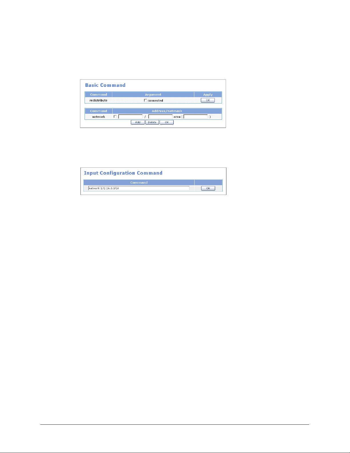
Home Page
Table of Contents
• Basic Command
After entering the items, click the [OK] button to display the applied value on the
<Current Configuration Status> window.
• Input Configuration Command
Select a command, as if selecting one from the <Command Help(RIP)> window, or
directly enter an OSPF command and click the [OK] button.
© SAMSUNG Telecommunications America, L.P.
76
Page 77

Home Page
Table of Contents
QoS Menus
Select the [QoS] menu to display the submenus of QoS on the upper left section of the window.
Menu Submenu Description
Group
Policy - Sets a class for a port
Status - Displays QoS class and filter data of a port in a tree
Management - Starts or stops the execution of a QoS and can set
Port Group Retrieves, sets, edits, or deletes a port group
IP Group Retrieves, sets, edits, or deletes an IP group
Filter Group Retrieves, sets, edits, or deletes a filter group
Class Group Retrieves, sets, edits, or deletes a class group
structure
whether to automatically execute the QoS when the
system is rebooted
© SAMSUNG Telecommunications America, L.P.
77
Page 78

Home Page
Table of Contents
Group
The [Group] menu is used to retrieve, set, edit, or delete a port group, an IP group, a filter
group, or a class group.
Port Group
Select [Port Group] to retrieve, set, edit, or delete a port group.
Click the [Add] button in the above window to display a window from which a port group can
be set. Enter the group ID, group description, and port number, click the [Add] button, and
click the [Save] button.
Item Description
Group ID Name of the port group
- Should include both letters and numbers
- Group ID shall start only with letters, not numbers
- No blanks should be left in between characters
Group description Description on the port group
Port Range of ports
Enter ‘0’ to set all ports
© SAMSUNG Telecommunications America, L.P.
78
Page 79

Home Page
Table of Contents
IP Group
Select [IP Group] to retrieve, set, edit, or delete an IP group.
Click the [Add] button in the above window to display a window from which an IP group can
be set. Enter the group ID, group description, and port number, click the [Add] button, and
click the [Save] button.
Item Description
ID Name of the IP group
- Should include both letters and numbers.
- Group ID shall start only with letters, not numbers.
- No blanks should be left in between characters.
Group description Description on the IP group
IP Address IP address
/: Used for entering subnet
-: Used for entering the range of IPs
Enter ‘0.0.0.0/0’ to set all ports.
© SAMSUNG Telecommunications America, L.P.
79
Page 80

Home Page
Table of Contents
Filter Group
Select [Filter Group] to retrieve, set, edit, or delete a filter group.
If ‘dev_voip’ is registered as the filter group as shown above, the filtering rule is as follows:
‘Source’ and ‘Destination’ are set in the [Port Group] menu and [IP Group] menu. All TCP
packet traffics of which the internal IP is Develop_Team(192.168.0.0/24) and the connection
port is VoIP(10000~20000) are filtered with a priority of ‘1’. The filter is then associated with
the class group set at the [QoS] Æ [Group] Æ [Class Group] menu.
Click the [Add] button in the above window to display a window from which a filter group can
be set. Set the items and click the [Save] button. Clicking the [Add] button displays a list of
port groups and IP groups. Select the IP and port from the list.
Setting a filter means setting a rule for filtering the values in the packet header. Values set at
the [QoS] Æ [Group] Æ [Port Group] menu and the [IP Group] menu is used, and protocols
and TOS fields can also be filtered. In addition, priorities can be set for the filters to apply the
filtering rules according to the priority.
The ‘Src IP’, ‘Src Port’ and ‘Dest IP’, ‘Dest Port’ are mandatory items and must be entered. If
these items are not entered, an error message will appear.
© SAMSUNG Telecommunications America, L.P.
80
Page 81

Home Page
Table of Contents
Class Group
Select [Class Group] to retrieve, set, edit, or delete a class group. A class includes information
on the defined filtering rule and the bandwidth that should be assigned to the filtered traffic.
Click the [Add] button in the <Class Group> window to display a window from which a class
group can be set. Set the items and click the [Save] button.
© SAMSUNG Telecommunications America, L.P.
81
Page 82

Home Page
Table of Contents
Item Description
Parent ID Due to the hierarchical characteristic of QoS, classes are classified
into the root class(highest level class) and the leaf class(lowest level
class) and into the parent class and the child class.
If the target class is a child class of another class, set the parent class
in the Parent ID item. Do not set the Parent ID if the target class is the
root class(highest level class physically connected to the device) or the
default class(class including the bandwidth for traffics that do not
belong to a filter).
Priority If several classes compete to occupy leftover bandwidths or if all
classes attempt to occupy excess bandwidth, set the priority so that
the class with the highest priority occupies the bandwidth first.
MTU The Maximum Transmit Unit(MTU) represents the maximum amount of
packets that can be transmitted at a time. It is recommended that this
setting does not exceed the maximum packet size(1504 Byte) of
Ethernet. If this item is not entered, the default value, ‘1500 Byte’, will
be applied.
Rate This is the basic bandwidth needed for setting class for an assigned
bandwidth.
Ceil Maximum value of assigned bandwidth.
Burst Size of data that can be sent by the class.
Cburst Maximum data size that can be sent at a time.
Filter List Sets filtering rules for the class.
Leaf Qdisc
Parameter
Scheduling
Parameter
1/2/3
Set a desired Qdisc for the Leaf Qdisc parameter when setting the
lowest level class.
Changes the bandwidth of the class based on day and hour.
Up to three scheduling parameter can be set.
© SAMSUNG Telecommunications America, L.P.
82
Page 83

Home Page
Table of Contents
Policy
The [Policy] menu is used for setting a class for a port. Enter the following items and click the
[Save] button to select a class for a port.
Item Description
Port Select a port(select WAN1, DMZ, LAN, WAN2, or SERIAL)
R2Q R2Q is used as a variable for calculating the amount of Deficit Round
Robin(DRR).(Bps/r2q)
Root Class Class connected to the port. Click the [Add] button and select the class
group from the class group list.
Default Class This class defines the bandwidth for incoming traffics that are not
applicable to all filtering rules. Click the [Add] button and select the
class group from the class group list.
Description Input the information on each device.
© SAMSUNG Telecommunications America, L.P.
83
Page 84

Home Page
Table of Contents
Status
The [Status] menu is used for displaying the class and filters assigned to each port in a tree
structure.
Management
The [Management] menu is used to start or stop the execution of a QoS. Execution of the
‘Scheduling Parameter’ set at the [QoS] Æ [Group] Æ [Class Group] menu can also be started
or stopped. Clicking the ‘Auto start’ item will automatically start the QoS service when the
system is rebooted.
© SAMSUNG Telecommunications America, L.P.
84
Page 85

Home Page
Table of Contents
Status Menus
Select [Status] to display the submenus of Status on the upper left section of the window.
Menu Submenu Description
Monitoring
Statistics
Serial State - Displays the current status of the serial line.
Services - Various functions of the Data Server are categorized into Security, Router, and
Sessions Displays IPs and ports connected to the Data Server.
Traffic Rate Displays the Data Server network real time statistics in a table format
History Displays the Data Server network statistics accumulated yearly, monthly,
weekly, and hourly in a graphic format
Devices Displays the network statistics of the Data Server for each device and for Tx
and Rx.
Protocols Displays the network statistics of the Data Server for each protocol.
Management, and the statuses of services are displayed in a table format.
© SAMSUNG Telecommunications America, L.P.
85
Page 86

Home Page
Table of Contents
Monitoring
The [Monitoring] menu displays the connection status of the Data Server, and the network statistics
of the Data Server in real time or in values accumulated during a certain period.
Sessions
The [Sessions] menu displays information on IPs and ports connected to the Data Server.
Item Description
Protocol Type of protocol used for session connection(UDP, TCP)
Src IP Source IP
Src Port Source port
Status - UNREPLIED: No response packets found on received packets
that requires response
- ASSURED: Response packet has occurred(‘UNREPLIED’
changes to ‘ASSURED’)
Dst IP Destination IP
Dst Port Destination port
© SAMSUNG Telecommunications America, L.P.
86
Page 87

Home Page
Table of Contents
Traffic Rate
Select [Monitoring] Æ [Traffic Rate] to display the network statistics of the Data Server in
real time. Data is updated every 5 seconds.
History
Select [Monitoring] Æ [History] to display the Data Server network statistics in values
accumulated yearly, monthly, weekly, and hourly. The History is useful for analyzing the
traffic patterns and trends on the network, and establishing the normal operating parameters.
© SAMSUNG Telecommunications America, L.P.
87
Page 88

Home Page
Table of Contents
Statistics
The [Statistics] menu displays the network statistics of the Data Server for each device and for
each protocol.
Devices
Select [Statistics] Æ [Devices] to display traffic and error statistics showing bytes, packets,
errors, drops, FIFO, Frame, Compressed, and multicast on the network. These statistics
information is useful for detecting changes in traffic and error patterns of the network.
Item Description
Devices Port type
Bytes Total bytes received or transmitted
Packets Total packets received or transmitted
Errs Number of failed packets
Drop Number of dropped packets
FIFO FIFO queue is full (FIFO overrun)
Frame Ethernet header type is invalid (Frame Alignment Error)
Compressed Number of compressed packets
Multicast Number of multicast packets
© SAMSUNG Telecommunications America, L.P.
88
Page 89
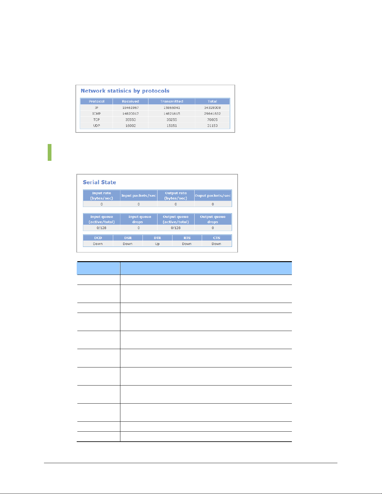
Home Page
Table of Contents
Protocols
Select [Statistics] Æ [Protocols] to display the network statistics of the Data Server for the IP
protocols, IP, ICMP, TCP, and UDP (Unit: Byte).
Serial State
This function is used to display multiple data traffic and status of the serial line.
Item Description
Input Rate Indicates the input packet rate.
Input
packets/sec
Output rate Indicates the output packet rate.
Output
packets/sec
Input queue Indicates the number of packets waiting in the input queue / maximum
Input queue
drops
Output queue Indicates the number of packets waiting in the output queue /
Output queue
drops
DCD Data Carrier Detect. Indicates the detection results of carrier sent by
DSR Data See Ready. Indicates the Tx/Rx setting status of DCE.
DTR Data Terminal Ready. Indicates the Tx/Rx status of the DTE channel.
Indicates the number of input packets per second.
Indicates the number of output packets per second.
size of the input queue.
Indicates the number of packets dropped in the input queue or
dropped in the serial network device
maximum size of the output queue.
Indicates the number of packets dropped in the output queue.
DCE.
© SAMSUNG Telecommunications America, L.P.
89
Page 90

Home Page
Table of Contents
Services
Item Description
RTS Request To Send. Indicates the status of the DTE Receive Mode.
CTS Clear To Send. Indicates the status of Tx/Rx setting.
The [Services] menu is used to display the statuses of security, router, and management
services, provided by the Data Server.
If the ‘Auto Start’ item is checked ‘On’, the service will be started automatically when the
system is rebooted. The ‘Activity’ item is set to ‘Running’ when the service is being provided,
and is set to ‘Stopped’ when the service is not being provided.
Security
This section displays the current status of security services: NAT, Packet Filtering, IPSec,
PPTP, and IDS.
Router
This section displays the current status of router services: RIP, OSPF, QoS, SIP ALG, NTP,
DHCP, SSH, and TELNET/FTP.
© SAMSUNG Telecommunications America, L.P.
90
Page 91

Home Page
Table of Contents
Management
This section displays the current status of management services: SM Module and Call, Feature
Module.
© SAMSUNG Telecommunications America, L.P.
91
Page 92

Home Page
Table of Contents
VPN Menu
The VPN capability creates encrypted ‘tunnels’ through the Internet, allowing branch offices
or remote users to securely connect into the network from off-site. VPN in OfficeServ 7200
Data Server supports both IPSec and PPTP solutions. The IPSec solution is supported for siteto-site (OS 7200 to OS 7200) connections and for individual remote access, allowing up to
100 secure tunnels. The PPTP solution is designed for remote client connection to OS 7200
only, a total of 25 PPTP connections are supported by OS 7200.
Please note that OS 7200 uses security processor (Hifn 7951) to implement the VPN functions
such as tunneling through the data encryption, decryption, and authentication to enhance the
system performance.
Select [VPN] to display the submenus of VPN on the upper left section of the window.
Menu Submenu Description
IPSec
Config Sets IPSec.
Management Allows/Disallows execution of IPSec. Sets whether to execute IPSec when the
system reboots.
Certification Creates and deletes the certification.
Status Checks if IPSec tunnel is properly connected.
Config Sets PPTP. PPTP
Management Allows/Disallows execution of PPTP. Sets whether to execute PPTP when the
system reboots.
Setting VPN Client in Windows XP/2000
OfficeServ 7200 Data Server supports Microsoft Windows PPTP and IPSec VPN clients. Please
refer to ‘APPENDIX A’ for detailed information on configuring MS Windows IPSec VPN client.
© SAMSUNG Telecommunications America, L.P.
92
Page 93

Home Page
Table of Contents
IPSec
IPSec (IP Security) is the Internet standard protocol for tunneling, encryption, and
authentication.
IP Security Protocol (IPSec) provides security services in the IP layer through implementing
Internet Key Exchange (IKE). IKE is an automatic keying mechanism, requiring two phases in
establishment of a VPN tunnel. Phase one establishes the Internet Security Association Key
Management Protocol (ISAKMP) tunnel that manages Phase two IPSec data tunnel.
OfficeServ 7200 IPSec supports the following parameters:
• Encryption cipher: DES or 3DES
• Modes: Main
• Keys: Pre-shared or Certificates
• Hash algorithm: MD5 or SHA1
• Transforms: Automatic Header (AH) or Encapsulation Security Payload (ESP)
• Diffie-Hellman Group: Group 2
• Perfect Forward Security (PFS): On or Off
OfficeServ 7200 supports the following three authentication methods:
• RSA key – for OS 7200 to OS 7200 connections only. A RSA key is literally a long
string of alphanumeric characters, which is the encoding of a public key. OS 7200 can
create new RSA key by selecting Create New Host Key under IPSec Management
menu.
• Pre-shared key – pre-shared key is simply non-encrypted passphrases stored in plain-
text. This is used to set up the connection with easy authentication.
• X.509 certificate – the X.509 certificate has the same encryption scheme as RSA keys
with certificates. The certificate contains useful auxiliary information and it allows a
trust-inheritance scheme.
OfficeServ 7200 supports Gateway to Gateway and Client to Gateway tunnels, allowing up to
a total of 100 tunnels. In the case of Gateway to Gateway tunnel configuration, in order to
establish a secure communication over the Internet with the remote site, both local gateway
and remote gateway should have the matching VPN parameters. The local VPN parameters on
one end must match the remote VPN parameters on the other end, and vice versa.
© SAMSUNG Telecommunications America, L.P.
IPSec Tunnel Mode
OfficeServ 7200 Data Server supports the IPSec tunnel mode only, it does not support the
Transport mode. If the WAN interface is used for serial, IPSec is not supported. Since the serial
line is used as leased line, you need not use IPSec for security.
93
Page 94

Home Page
Table of Contents
Config
Users are allowed to add, delete, and search an IPSec tunnel on the [IPSec] Æ [Config] menu,
and to set detailed items.
The menu buttons are defined as shown below:
Button Description
Add Creates IPSec tunnel
Delete Deletes IPSec tunnel
Edit Modifies IPSec tunnel data
Advanced Sets detailed items of IPSec tunnel
Add
Click the [Add] button from the <IPSec Connections> window to display the window below:
Enter each item value and click the [Add] button to add an IPSec tunnel.
Category Description
Connection ID ID composed of certain letters(Required)
IP Address External IP address(Required)
Router Router IP address
Subnet IP Internal IP address
Subnetmask Internal subnetmask
© SAMSUNG Telecommunications America, L.P.
94
Page 95

Home Page
Table of Contents
Category Description
RSA Key/
Pre-shared Key
/X.509 Cert
Selects host authentication method
- RSA Key: Public key is RSA key of Local settings. Click the [Download] button to store
RSA key to your PC, and send it to other PC through a path. After RSA key of Remote
settings receives file in the target PC through a path, click the [Upload] button to enter a
key value.
- Pre-shared Key: Authentication method entering password.
- X.509 Cert : Authenticate using your own certification and the CA certification. In the
Local settings side, enter the file name of your own certification directly, or click the [List]
button and select from the current authentication list.(If you select the Certification, the
Advanced Left ID is automatically entered). In the Remote settings side, click the
[Upload] button to upload the CA Certification of the other party. You can check the host
certification registered in Local and integrity.
If the ‘Router’ item value is not entered, the ‘IP address’ item of the Local settings and Remote
settings will be used as the ‘Router’ item.
If the ‘Subnet IP’ item value and the ‘Subnetmask’ item value are not entered in the Remote
settings, the security tunnel between local subnet and remote host will be added. Then, remote
IPSec client can operate as a part of local subnet.
Setting Router Value
If the IP address(in other words, the result of netmasking the IP Address)of ‘Local settings’ is the
same as the ‘IP Address’ of ‘Remote settings’, enter the ‘IP Address’ of ‘Remote settings’ in the
‘Router’ of ‘Local settings’, and enter the ‘IP Address’ of ‘Local settings’ in the ‘IP Address’ of
‘Remote settings’.
Setting Connection ID
Connection ID should be English alphabets or the combination of English alphabets and
numbers, and the first letter should start with English alphabet.(ID should not be configured
using numbers only.)
© SAMSUNG Telecommunications America, L.P.
95
Page 96

Home Page
Table of Contents
Advanced
Click the [Advanced] button from the <IPSec Connections> window to display the window
below: Detailed items of IPSec can be set.
The ‘Advanced’ menu is set only if the authentication is performed using X.509 Cert.
Item Description
Auth Select packet authentication protocol.
- Authentication Header (AH): Allows data sender authentication.
- Encapsulating Security Payload (ESP): Allows sender authentication
and data encryption.
PFS Perfect Forward Secrecy; select whether to use the security for
session key delivery
-YES, by default it is set to ‘yes’.
- NO. Set to NO if the system is connected to a third party client
software that does not support PFS.
Key lifetime Cycle of newly added key used in packet encryption through repeated
IKE 2 level.
IKE lifetime IKE duration time
If duration time passes, host authentication (IKE 1 level) is performed
again.
Re-Key Set whether to add a new key(whether to add a new key and negotiate
again in the IKE 2 level).
Keyingtries Retry count of key exchange when encryption key exchange fails in
the IKE 2 level.
Left ID Set ID if ID as well as IP address is required. Typically, IP address is
used for authenticating other host in the IKE 1 level.
Right ID Set ID if ID as well as IP address is required. Typically, IP address is
used for authenticating other host in the IKE 1 level.
© SAMSUNG Telecommunications America, L.P.
96
Page 97

Home Page
Table of Contents
You may change the values of PFS or Key lifetime for compatibility with other systems. If
‘Left ID’ and ‘Right ID’ are not set, the IP address replaces the value.
In X.509, enter the subject of a certification in ‘Left ID’ and ‘Right ID’ of ‘advanced’.
Management
The user allows/disallows executing IPSec services on the [IPSec] Æ [Management] menu.
Check the ‘Auto-start when system boots’ item, and click the [OK] button to execute the IPSec
services automatically while the system reboots.
Click the [OK] button of the ‘Create new host key’ item to add a new RSA (public key
password method) key. Use this menu to add a new RSA key if the host authentication method
of RSA key used.
© SAMSUNG Telecommunications America, L.P.
97
Page 98

Home Page
Table of Contents
Certification
This function is used to issue/delete/download the CA certification and host certification, and
to view a list of current certification.
The table below explains the menu buttons:
Item Description
(CA) Add Creates the CA certification
(CA) Delete Deletes the CA certification
(Host) Add Creates the host certification
(Host) Delete Deletes the host certification
© SAMSUNG Telecommunications America, L.P.
98
Page 99

Home Page
Table of Contents
Item Description
Country name Country name(2 characters ex. kr, cn)
State or Province name State or province name
Locality name Locality name
Organization name Company name
Organization unit name Organization(department) name
Common name User Name
Email address email address
Password Certification password
Status
Users are allowed to check if the target IPSec tunnel is connected properly on the [IPSec] Æ
[Status] menu.
Item Description
Common name User Name
Email address email address
Password Certification password
© SAMSUNG Telecommunications America, L.P.
99
Page 100

Home Page
Table of Contents
PPTP
Config
Point to Point Tunneling Protocol, PPTP, is a proposed standard sponsored by Microsoft as an
extension of the Internet’s Point-to-Point Protocol. Any user of a PC with Windows 98 or
above is able to use an Internet service provider to connect securely to OfficeServ 7200 data
network. Since PPTP setting is convenient compared with IPSec and the client S/W is
provided by Windows OS, the user can use VPN functions easily. OS 7200 supports a total of
25 PPTP connections.
Users are allowed to add, edit, delete, and search VPN tunnel data on the [PPTP] Æ [Config]
menu, and to set detailed items.
The menu buttons are defined as shown below:
Button Description
Add Create PPTP users
Delete Delete PPTP users
Edit Modify PPTP user data
© SAMSUNG Telecommunications America, L.P.
100
 Loading...