

office bricks MOBILE UNIT Installation Instructions Manual
INSTALLATION INSTRUCTIONS - SOUND
INSULATING CABIN „MOBILE UNIT“

2

CONTENT
1 . Scope of delivery ..................................................................... 4
2. Installation preparation ........................................................ 6
2.1 Work safety ........................................................................ 6
2.2 Tools ...................................................................................... 7
2.3 Location of installation / Technical Data ................. 8
2.4 Sorting the parts .............................................................. 9
3. Setting up the cabin ...................................................... 11
3.1 Scruing the floor plate with wedges ......................11
4. Installation of walls and door/windows .......................12
4.1 Instructions regarding brick connections ...........12
4.2 Row A and glass door ...................................................14
4.3 Installing the brakes .......................................................17
3
4.4 Wood fibre and floor plate .........................................18
4.5 Rows B, C, D and shelf ....................................................19
5. Roof assembly and electric connection ........................ 23
5.1 Installing the roof...........................................................23
5.2 Connections fan and LED .............................................25
6. Carpet tiles ...............................................................................30
7. Maintenance and care ..........................................................30
8. Dissassembly...........................................................................32
4
SCOPE OF DELIVERY
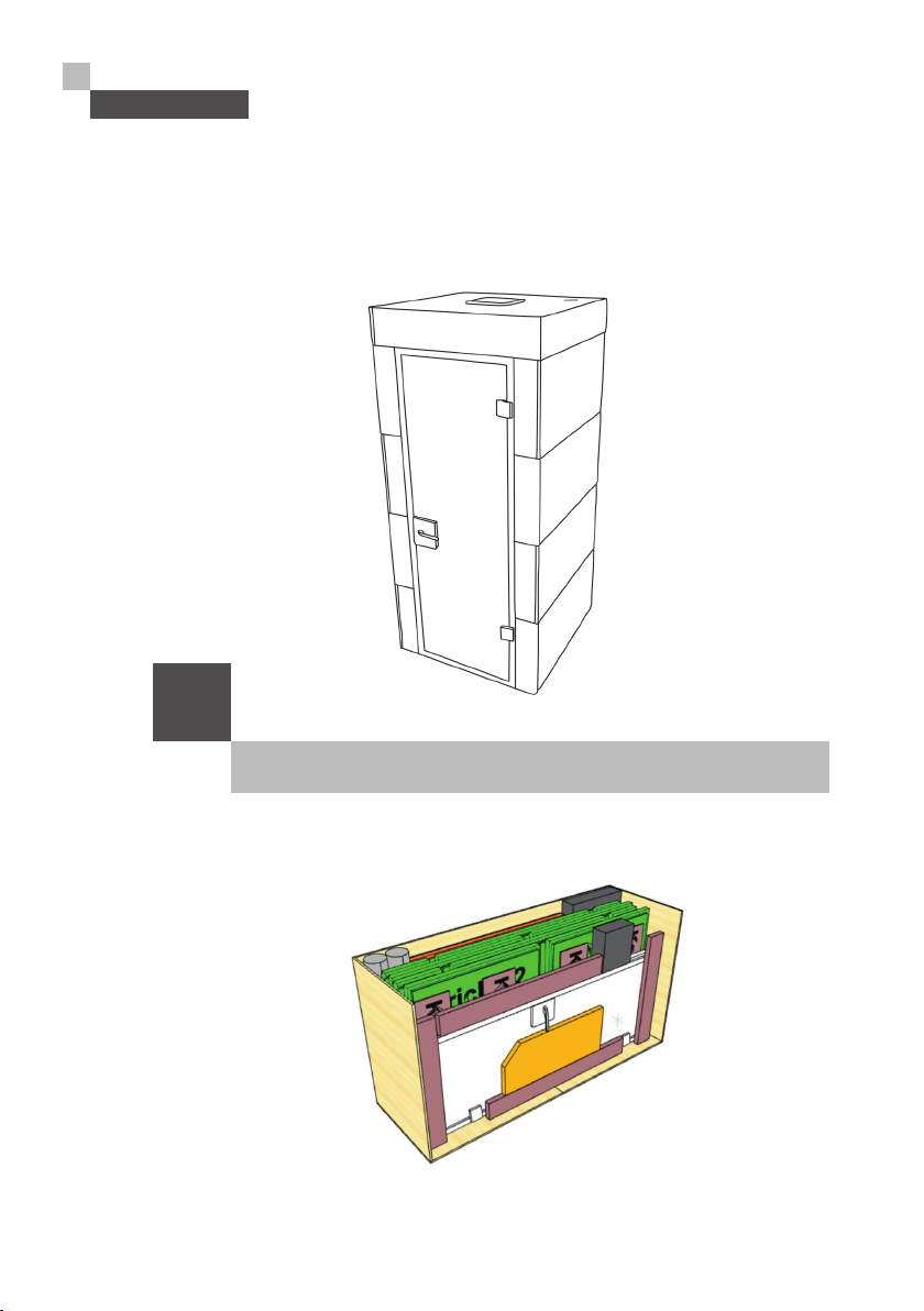
1 Scope of delivery
i
The cabin parts are delivered in one wooden box.

SCOPE OF DELIVERY
Contents Wooden Boxes:
1 x Floor plate, MDF 38 mm
4 x Skirting board
20 x Bricks (rows A-D)
1 x Glass door with wooden frame
1 x Floor insulating plate, wood fibre 35 mm
1 x Floor plate, chipboard panel white, 16 mm
1 x Shelf with screws for attachment
1 x Roof plate, chipboard 19 mm white with LED Panel, motion detector and
motion detector box
1 x Roof plate, wood fibre 35 mm
4 x Roof lining boards wood fibre
4 x Roof frames chipboard
3 x pipe elbows
2 x Ventilation tubes
1 x Fan
1 x Accessories box
1 x Box with carpet tiles
5
Contents Accessories Box:
1 x Disassembly wooden wedge
8 x Adjustable feet
2 x brakes (with screws)
4 x Wooden wedges to secure floor plate
1 x Transformer for LED Panel
1 x Ventilation valves for 8 mm roof
1 x strip with 3 sockets
1 x tapping block
6 x platelets in different sizes
6
INSTALLATION PREPARATION
2 Installation Preparation
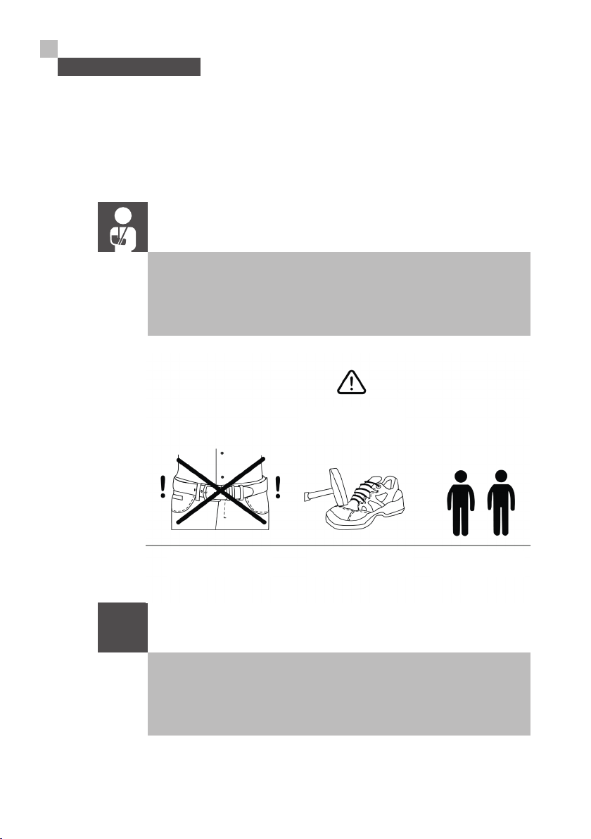
2.1 Work safety
During assembly, please wear suitable clothing and the required
protective equipment, e. g. shoes with reinforced caps. Climbing
aids or ladders will be needed. At least two fitters are required to
set up the cabin. safely.
CAUTION!
Do not we ar belt buckles
(to avoid marks/scratches)
Wear safetey shoes
2 fitt ers are necessar y
!
Important note: Avoid hard elements on clothing such as belt
buckles, rivets, protruding zippers, etc.
These could cause scratches or damage to the frames when
handling door and window elements.
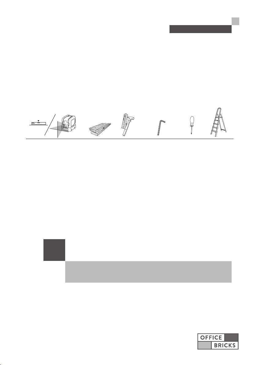
2.2 Necessary tools
7
INSTALLATION PREPARATION
Spirit level or laser levelling device
(for floor alignment)
2 wooden strips
(for door alignment)
2.3 Location of installation / Technical data
i
Please note the technical data for further information regarding
the location of inst allation.
Hammer + B oard
(to cor rect jo int pat tern if
necessary)
- NOT INCLUDED -
6 mm hex wr ench
(to ali gn the
feet screws)
Philip s head
screwdriver
(to fi x the scr ews on th e
shelf and brakes)
Ladder
(for Br ick row D & ro of)
8
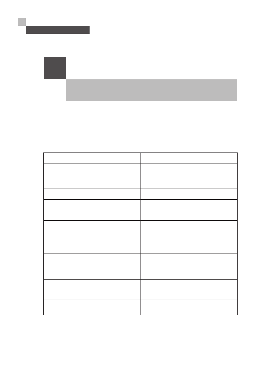
INSTALLATION PREPARATION
i
Technical data
Weight of the cabin 350 kg / incl. packaging 500 kg
Outer dimensions of assembled booth Height: 238 cm
Operating Voltage 220 V
Operating temperature 10 – 40 ° C
Air humidity during operation May be 40 - 60 %
Change interval for air filter As soon as the red diode lights up on
Cleaning interval The cabin must be cleaned on the
Mininum size 2.5 m x 2.5 m with a ceiling height of
When installing two or more cabins next to each other a mininum
distance of 5 cm bet ween the cabins has to be maintained.
Width: 106 cm
Depth: 106 cm
the fan, the filter must be replaced.
This diode can be seen underneath
the fan cover on the roof of the booth.
inside and outside every 40 operating
hours.
2.60 m
Number of users 1
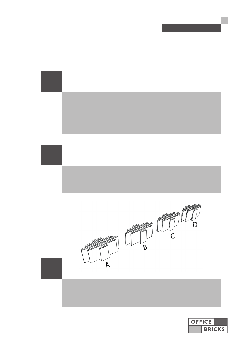
2.4 Sorting the par ts
i
Before assembly, sort all parts in the order of assembly. Divide
the components into the rows A-B-C-D, floor elements and
ceiling elements. This preparation will help you to ensure quick
and smooth assembly. When removing the parts from the
packaging, make sure that all parts are intac t and complete.
i
Complaints regarding damaged or missing parts must be made
before assembly! Please ensure that the bricks do not tip over to
avoid damage.
9
INSTALLATION PREPARATION
i
The bricks must not be pushed when lying on the visible sides,
otherwise scratches may occur. Also make sure that the bricks do
not tip over to avoid damage.
10
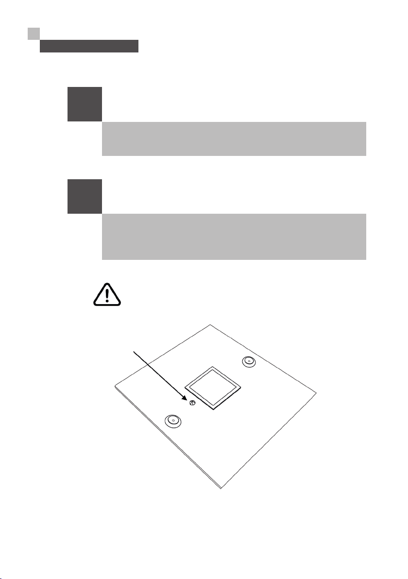
INSTALLATION PREPARATION
i
i
The elec tric brick and the fan must not be carried on the power
cable.
Do not place the inside of the ceiling panel on the floor. The
motion detector positioned there is protruding, it could be
damaged.
Caution
The moti on detect or must
not be damaged!
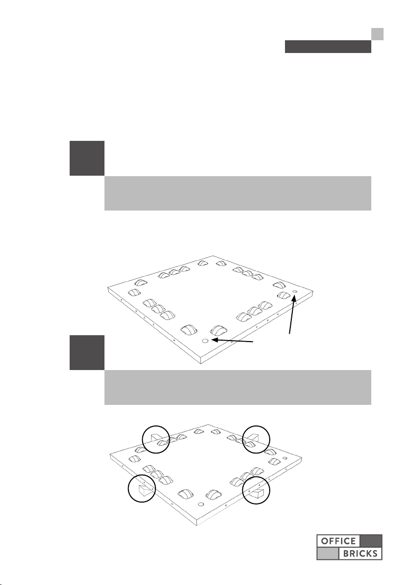
3. Setting up the cabin
3.1 Scruing the floor plate with wooden wedges
i
When positioning the floor plate make sure that the floor is not
sloping
Back
11
ASSEMBLY OF THE CABIN
Front
i
The floor plate has to be secured with the wooden wedges to
prevent it from roling away.
Back
Front
 Loading...