

OERTLI AMERICAN OE-22, OE-2, OE-21 Service Manual
MANUAL NO. 17,000
lSOOOlg-82
YI
INSTALLATION
SERVICE
CERTLI
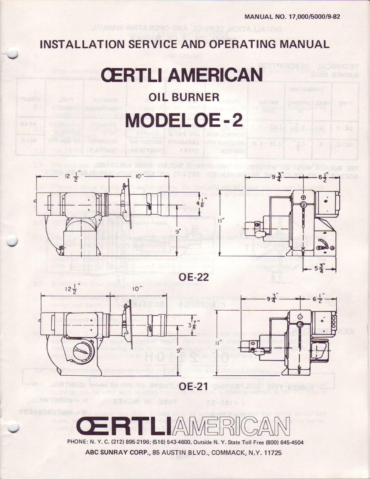
MODELOE.z
AMERICAN
OIL
AND
OPERATING
BURNER
MANUAL
,+'--1-5{
I
e
o
\
rFl
J
J
I
I
tDng
r
,a
5{'
oE-22
oE-21
J
CERTLIANtrRIGAN
PHONE:
N. Y.
ABC
C.
.2121895-2196;
SUNRAY CORP.,85
{516)
543-4600.
AUSTIN BLVD.,
Outside
N. Y.
State Toll Free
COMMACK, N.Y. 11725
(800)
645-4504
INSTALLATION.
SERVICE
ltiODEL
AND
OE-z
OPERATING
BURNER
OIL
IIANUAL
v
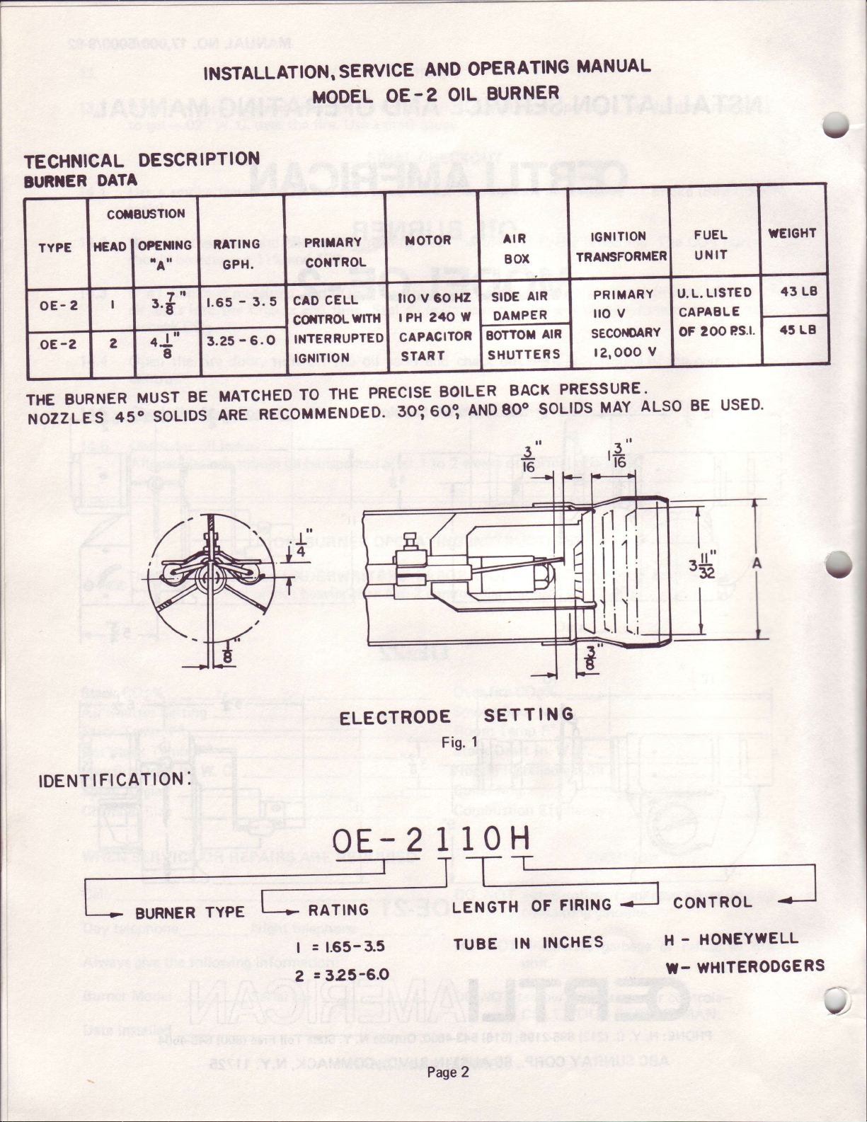
TECHNICAL
IUR]IER
BURNER
THE
NOZZLES
DESCRIPTION
DATA
MUST
450
BE
soLlDs
LISTED
L.
-
t.65
3.5
MATCHEDToTHEPREc|sEBo|LERBACKPRESSURE.
ARERECoMMENDED.So?600'ANDEoosoL|DsMAYALSoBEUSED.
CELL
CAD
COfTROLWITH
INTERRUPTED
IGNITION
lto
tPH240W
CAPACITOR
START
v 60
Hz
U.
CAPABLE
Ps.l.
200
oF
1
I
9
IDENTIFICATION:
BURNER
TYPE
ELECTRODE
0E-
RATING
=
1.65-3.5
|
:325-6.O
2
2
SETTING
1
Fig.
10H
1
LENGTH
TUBE
-
OF
INCHES
IN
FIRING
l
I
I
CONTROL
-
HONEYWELL
H
WHITERODGERS
U-
I
-
Page2
INSTALLATION
FUEL OIL
# 2
INSTR UCTIONS
BURNERS
1.
1.1
When unpacking
packing
list, electrical
2.
All oil storage
2.1
Underwriters
2.2
2.3
2.4
2.5 The
3.
3.A 275-Gal.
pipe
All
(stick
well
The filf line
The vent
the vent
ground
pipe
tank
tanks,
UNPACKING
the burner,
rating
tanks must be U.
local
or
connections on underground
well).
must
pipe
should not be lessthan
toward tank Yo"
gauge
protect
Basement
ordinances,
pitch
toward
should be
the
Tanks-Gravity Feed.
be sure all
(voltage,
To"
per
installed so that the
and
bulb
hertz) and for concealed
listed
L.
whichever
buried
per
tt.
1y4" l. P. S. and equipped
ft.
gauge
packages
loose
FUEL
TANK
installed according
and
precedence.
has
tanks must have sruing
float
vvill
inside the tank with rigid
line
PIPING
OIL
inspected
are
damage.
with an approved vent
not be
for
to the National Board of Fire
joints
under
iron
contents. Gheck
except
the fill
pipe.
the sounding
cap. Pitch
line.
On
the
under-
3.1 UseYz" O. D.
for
other
3.2 Install an approved
filter. Connect the filter to the
ly to the
3.3
3.4
3.8
3.5
3.6
3.7
A return
more than one
lf
pumps
Underground
l)se
connections.
fittings with
manufacturer's specifications
Both
Slip
bushings
preferred.
and
Tr" O.
suction and return
fittings should
copper tubing with
sizes and iron
pump.
not required for
line is
burner is connected
the size of
Vaulted
or
D. copper
tf the
double sruing
can be used
flared fittings. Consultthe
pipe
substitution.
hand
line and
Tanks.
tubing
local regulations
lines should
be used on
with wrought-iron
in the
valve
pump
this type
filter
with flared
joints
to
for other
the
with
to suction
must be increased.
require
prevent
sizes and
extend
tank for copper
tank
outlet
a copper
installation.
line,
fittings
for suction
rigid
breakage
iron
to within
pipe;
however, a
pump
and close
tube
the tank bottom
pipe,
in case the
pipe
4"
to burner
pigtail.
use
of
suction
Do
return lines
and
black wrought
tank settles.
substitutions.)
the tank
and return
bushing
manufacturer'sspecifications
pump
fuel
not connect rigid
be above both
must
to
bottom.
lines. Double-tapped
welded to the
ahead of the
pipe
underground
avoid
iron
and
(Consult
dip tube
direct-
burner
malleable
pump
the
is
valve and spring
3.8
J
Install,
check. When
install a vertical check valve
in the suction
the
line at an outside
is
tank
vaUlted
as close
and
to the
wall, an approved
the bottom of
top
of
Page
the tank
3
the tank
hand
is on the
practical'
as
same level
loaded ball
as the burner,
3.g
3.10
1
3.1
g.12
3.13
4.
thetank
bottom
the
lf
highest
the
at
lnstall
filter
lnsta
Avoid
hangers
A separate
provided , ,pting-jouJed
an
the
to
a copper
ll
fastening
with
of
Point.
approved
pump
with
tube
suction
rubber
so-ft
suction
hand
a
pigtail
line should
is above
close
valve
copper
and
lining
ball check
tube
between
return
prevent noise
to
be
levelof
the
to
pigtail'
pu
the
lines
used
installed
is
FUEL
the
burner
the
mp and
floor
to
transmission.
each
for
in the
FILTER
OIL
anti-siphon
burner,
spring-loaded
beams'
burner.
an
pump,
lf
A common
return
ahead
necessary
pipe
from
of
ball
valve
filter,
the
check
to do
return
each
is usually
and
return
in the
use
so,
line
fuel unit'
required
connect
line'
fitting
loose
be used'
may
the
4.1
4.2
4.3
5.
5.1
5.2
5.3
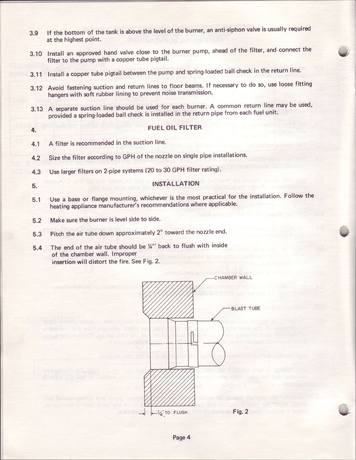
5.4
A filter
size
Use
Use
heati
Make
Pitch
The
of
insertion
is recommended
the
larger
base
a
appl
ng
sure
the
end
chamber
the
according
filter
on
filters
flange
or
iance
burner
the
tube
air
the air
of
wall.
willdistort
suction
in the
to GPH
2-pipe
mounting,
mi nufacturei's
level
is
approximately
down
tube should
lmProPer
the fire.
of
systems
whichever
recommendations
to
side
be
See
line'
toward
2o
back
is
on
the
to
nozzle
the
(20
to 30 GPH
INSTALLATION
side.
Tt"
2.
Fig.
single
filter
most
where
nozzle
the
flush
pipe
installations.
rating).
practical for
icab
appl
end.
inside
with
CHAMBER
the
le.
WALL
ELAST
installation'
TUBE
Follow
the
3
Page
Fig.2
4
v
 Loading...