

OERTLI PK 550 Assembly Manual
PK 550
Fuel oil/gas boilers
300020196-02
en
Assembly
Instructions
D000913

2
PK 550 18/03/2016 - 300020196-02
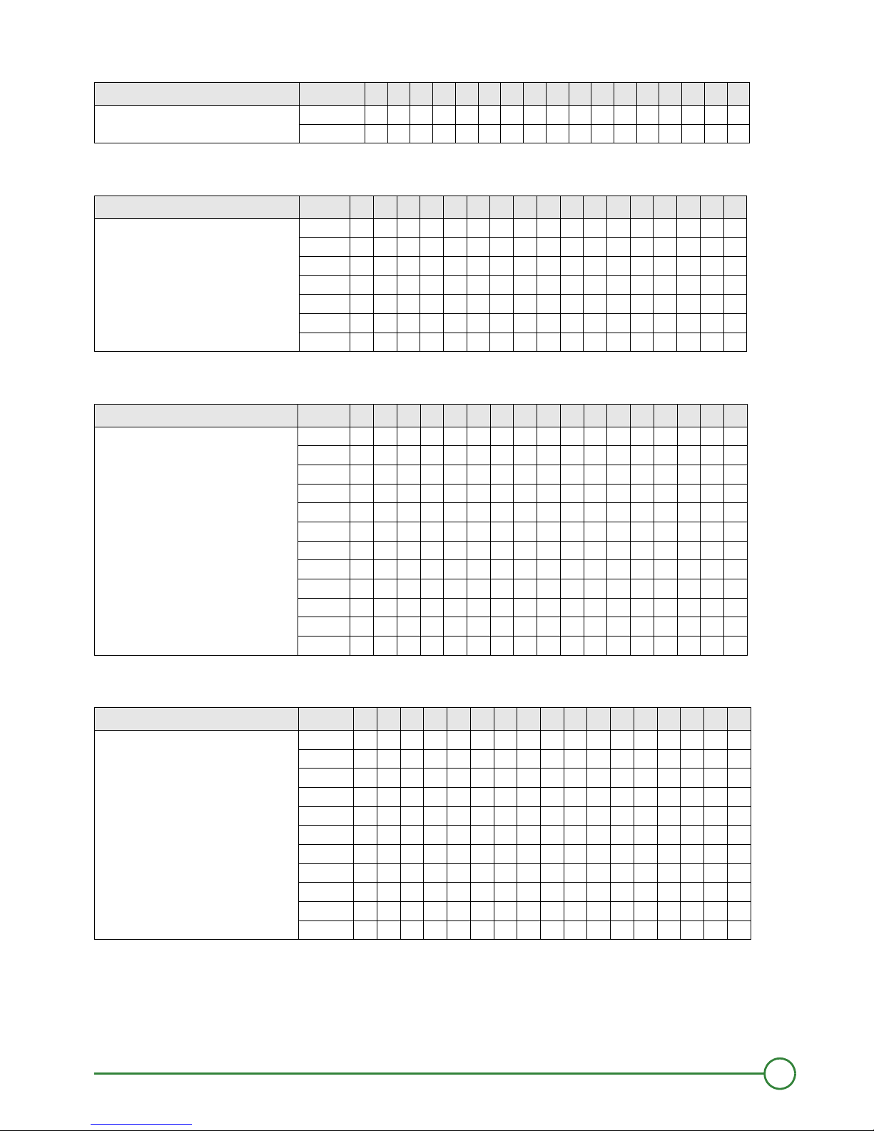
1. Package list
1 Package list
Before starting to assemble the boiler, refer to the table below to check if you have received all the packages required.
• Boiler body + Accessories
- Boilers supplied with an assembled body
- Boilers supplied with an unassembled body
(1)
The distributing tube fitting for PK 550 boilers with 15 to 19 sections is included in the accessory package.
(2)
The diaphragm for PK 550 , 13 and 14 section boilers is delivered in the additional accessory kit package.
Boiler PK 550- Number of sections 9 10 11 12 13 14 15 16 17 18 19 20 21 22 23 24 25
Assembled boiler body (contents depend upon model) 1 1 1 1 1 1 1 1 1 1 1 1 1 1 1 1 1
Cleaning tool kit (contents depend upon model) 1 1 1 1 1 1 1 1 1 1 1 1 1 1 1 1 1
Boiler PK 550- Number of sections
packag
e
9 10 11 12 13 14 15 16 17 18 19 20 21 22 23 24 25
Base frame (dimensions depend upon model) 1 1 111111111111111
Rear section 11111111111111111
Normal intermediate section 4567891011121314141516171819
Special intermediate section 33333333333444444
Front section 11111111111111111
Set of assembly rods + Cleaning tools (contents
depend upon model)
11111111111111111
Standard accessory kit
(contents depend upon model)
1
FA 44
FA 45
FA 46
FA 47
FA 48
FA 49
FA50
(1)
FA51
(1)
FA52
(1)
FA53
(1)
FA54
(1)
FA55
FA56
FA57
FA58
FA59
FA60
Additional accessory kit (contents depend upon
model)
(2)
1
FA63
FA64
FA65
FA66
FA67
(2)
FA68
(2)
FA69
FA70
FA71
FA72
FA73
FA74
FA75
FA76
FA77
FA78
FA79
Plain furnace plate 11111111111111111
Flue gas connection plate with opening
Ø 300
Ø 350
Ø 400
1
1 1 1 1
1 1 1 1 1 1 1
Plain flue gas connection plate 11111
Flue gas box 11111111111111111
Distributing tube fitting
(1)
(1) (1) (1) (1) (1)
111111
3
18/03/2016 - 300020196-02 PK 550
1. Package list
• Baffles
• Casing fittings
• Casing, variable parts
• Insulating material for body
Boiler PK 550 - Number of sections package 9 10 11 12 13 14 15 16 17 18 19 20 21 22 23 24 25
Baffles CM 22 1 11111
CM 23 1111111111222222
Boiler PK 550 - Number of sections package 9 10 11 12 13 14 15 16 17 18 19 20 21 22 23 24 25
Casing fittings MS1 111111111
MS2 11111111
MR3 1
MR4 1 1 1 1 1 1 1 1
MR5111 11 111
FA10 1 22 221 2211
FA11 11 222112332233
Boiler PK 550 - Number of sections package 9 10 11 12 13 14 15 16 17 18 19 20 21 22 23 24 25
Casing, variable parts FA16 11111111
FA17 1
FA18 1
FA19 1 1
FA20 1 1
FA21 1 1
FA22 1 1
FA23 1 1
FA24 1 1
FA25 1
FA26 1
FA27 1
Boiler PK 550 - Number of sections package 9 10 11 12 13 14 15 16 17 18 19 20 21 22 23 24 25
Insulation FA31 1
FA32 1
FA33 1 1
FA34 1 1
FA35 1
FA36 1 1
FA37 1 1
FA38 1
FA39 1 1
FA40 11
FA41 1
4
PK 550 18/03/2016 - 300020196-02
1. Package list
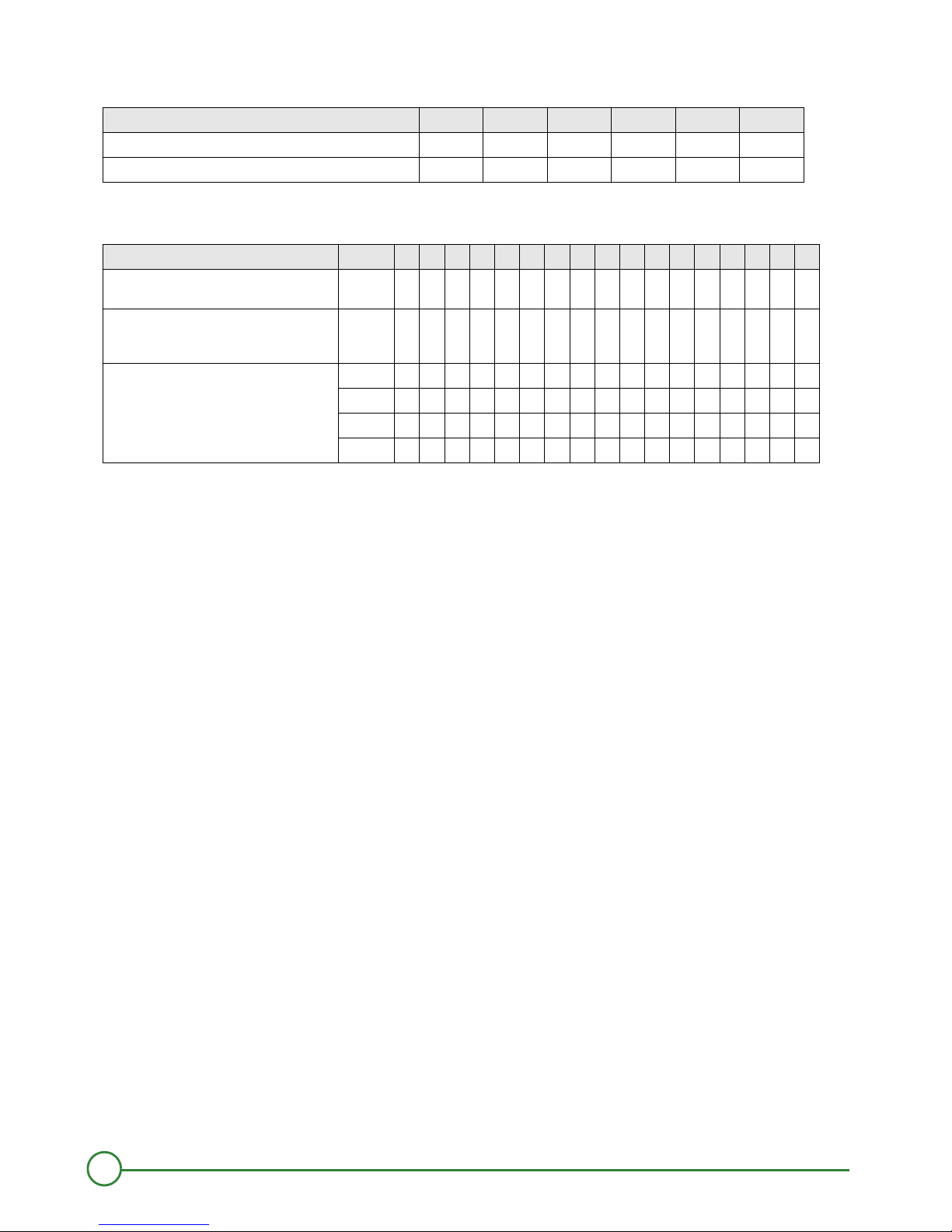
• Control panel
All models can be equiped with one of the following control panels:
• Accessories - Available as an option*
* Refer to the applicable price list for the other optional features (control units etc.) which may be used with these boilers.
Boiler PK 550 - Number of sections 9 10 11 12 13 14
Standard control panel - X 1 Package MG1 MG1 MG1 MG1 MG1 MG1
R control panel 1 Package MG2 MG2 MG2 MG2 MG2 MG2
Boiler PK 550 - Number of sections 9 10 11 12 13 14 15 16 17 18 19 20 21 22 23 24 25
Furnace plate with hole
Ø 165 / 186 / 210 / 240 or Ø 295
11111111111111111
Connecting plate with opening or plain connecting
plate - Ø 300
or Plain connection plate
11111111111111111
Set of anti-vibration studs 8208-7757 1
8208-7758 1111111
8208-7759 1111
8208-7760 11111

5
18/03/2016 - 300020196-02 PK 550
2. Mounting PK 550
2 Mounting PK 550
2.1 Introduction
Warning: Assemble the boiler in the order given by the numbers of each figure, in compliance with all the instructions.
Refer to the applicable price list for any optional features used.
Tools required
- 1 JD-TE or JD-TE Plus assembly tool
- 1 Flat screwdriver
- 1 "n°2 posidrive" screwdriver
- 1 10, 13, 16, 17 spanners, 18, 19
- 1 22 tubular box spanner
- 1 27 tubular box spanner
- 1 electric screwdriver + 1 "n°2 Philipps" screwdriver bit
- 1 Stanley knife
- Silicone filler (Supplied)
Boilers supplied with an assembled body
- Hydraulic test: See fig. 17
- Mounting: start assembly from figure 34
6
PK 550 18/03/2016 - 300020196-02
2. Mounting PK 550
Assemble the boiler body from the rear to the front:
- assemble the rear section,
- assemble all the normal intermediate sections,
- assemble all the special intermediate sections,
- assemble the front section.
The number of sections of each type is provided in the table below
Rear section
Normal intermediate section
Special intermediate section
Front section
Section type
PK 550-9 1431
PK 550-10 1531
PK 550-11 1 6 3 1
PK 550-12 1731
PK 550-13 1831
PK 550-14 1931
PK 550-15 11031
PK 550-16 11131
PK 550-17 11231
PK 550-18 11331
PK 550-19 11431
PK 550-20 11441
PK 550-21 11541
PK 550-22 11641
PK 550-23 11741
PK 550-24 11841
PK 550-25 11941
104
8228-0004
8228-0001
111
2
8228-0002
151
3
8228-0003
104
4
7
18/03/2016 - 300020196-02 PK 550
2. Mounting PK 550
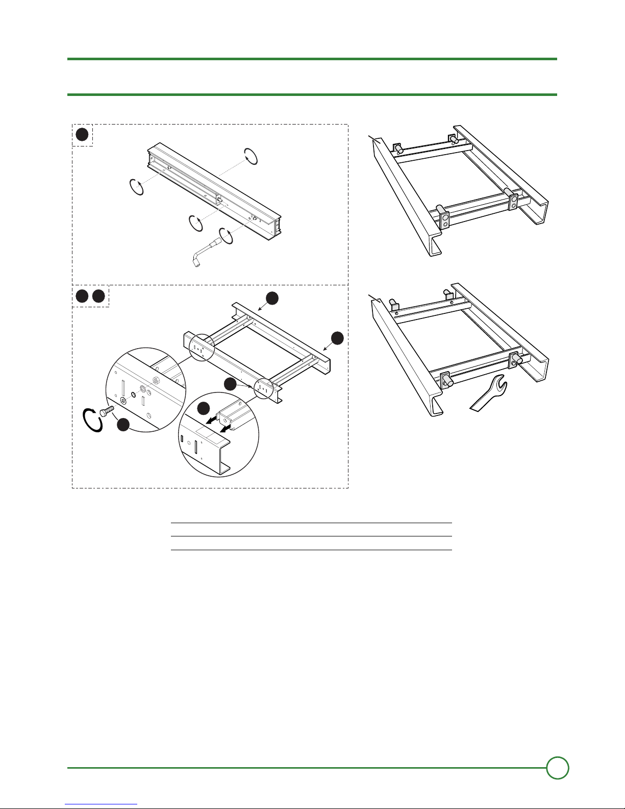
2.2 Mounting PK 550
1
`
to : Assembly of the base frame, delivered unassembled.
` Place the frame on the floor, taking care to note the TOP and FRONT positions
` Fit the fastening brackets as shown, depending on the type of boiler (1 Screw Ø 12x40 - 19 spanner)
DESS
US
NOBE
TOP
NAVA T
VORN
FRONT
DE
SSU
S
O
BE
N
TOP
ANTA
V
VORN
F
OR
NT
3
3
M000309
3
1
2
3
2
3
E
D
S
S
U
S
O
B
E
N -
T
O
P
DE
S
S
U
S
OBEN
TOP
DES
S
U
S
O
B
EN
T
O
P
D
E
SS
U
S
O
B
E
N
- TO P
48555N0 2A
F
R
ONT
V
O
R
N
A
V
A
NT
FR
O
N
T
VO
RN
A
V
ANT
F
R
O
N
T
V
O
R
N
A
V
A
N
T
F
R
O
N
T
V
OR
N
A
V
A
N
T
19
A
B
A Boilers: 10, 12, 14, 16, 18, 20, 22, 24 sections
B Boilers: 9, 11, 13, 15, 17, 19, 21, 23, 25 sections
8
PK 550 18/03/2016 - 300020196-02
2. Mounting PK 550
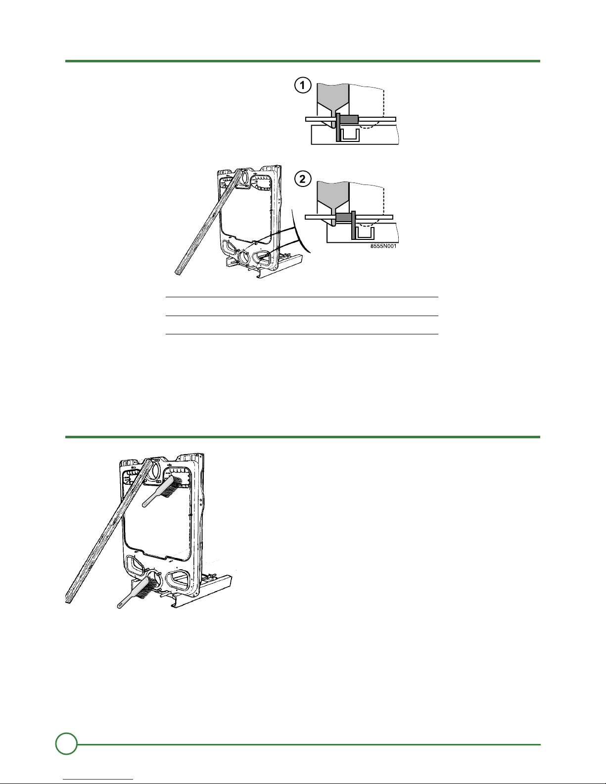
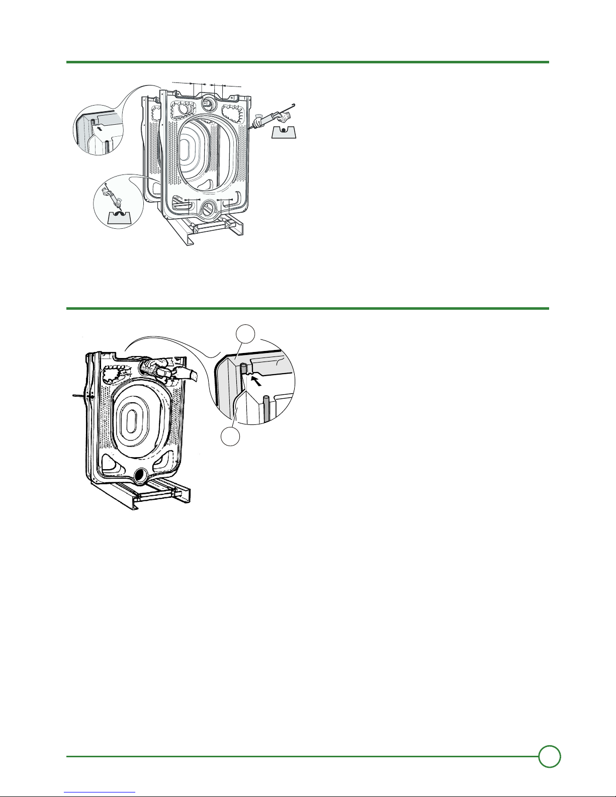
2
` Establish the location of the frame on the basis of the opening direction of the furnace door and the length of the burner. Leave enough
clearance at the rear of the boiler for water connections and the distributing tube.
` Fit the rear section on the frame, behind the fastening brackets (see detailed drawing) and prop it up.
` Insert the lower assembly rods in the holes of the rear section and the fastening brackets of the frame, in order to position the rear section
correctly according to the frame
3
` Clean all the openings in the section with a brush. Remove any deposit on the bottom of the section.
Boilers: 10, 12, 14, 16, 18, 20, 22, 24 sections
Boilers: 9, 11, 13, 15, 17, 19, 21, 23, 25 sections
00 8
M00 5
9
18/03/2016 - 300020196-02 PK 550
2. Mounting PK 550
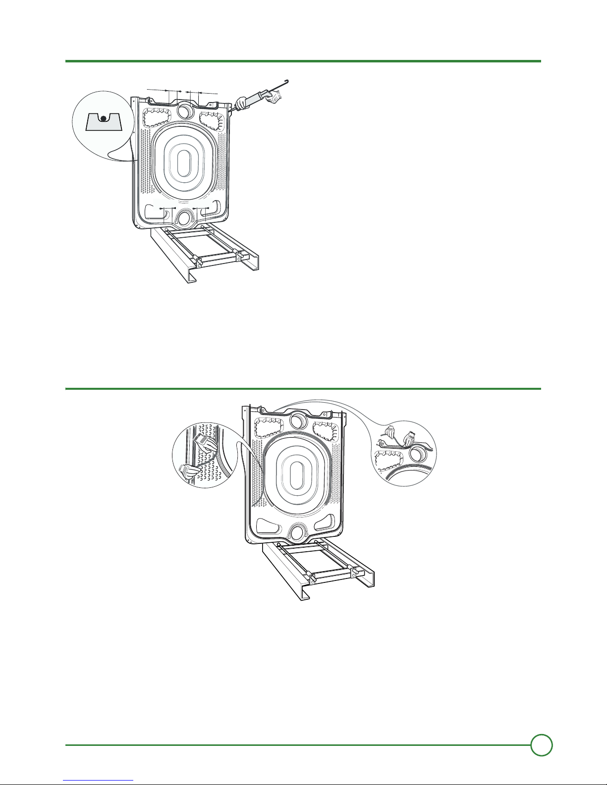
4
` Fill the bottom of the U groove (located on the periphery of the section) with a continuous bead of DOW CORNING silicon, diameter
approximately Ø 5 mm.
silicon must not be applied 100 to either side of the connection (nipple assembly area).
Dimensions are given in millimeters.
5
` Fit the Ø 10.5 mm diameter thermocord into this U groove and into the groove which circles the furnace.
Note: Do not pull on the seal while inserting it. Otherwise, you may stretch it and reduce its thickness.
M000059
100
100
001
100
a
M000060
10
PK 550 18/03/2016 - 300020196-02
2. Mounting PK 550
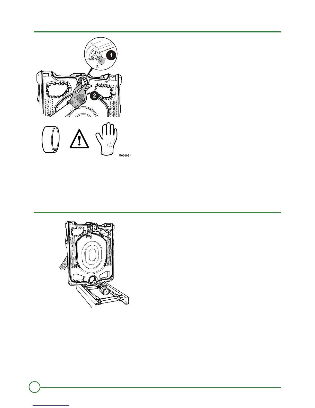
6
(1) Sandpaper
Handle the nipples with gloves, there might be sharp edges.
Remove any traces of rustprotective paint so that the surface is perfectly smooth.
Smear the nipples with the greasing product provided.
7
` Gently push in the 2 nipples.
A
R
R
I
ÈR
E
D
ES
S
US
O
B
E
N
T
O
P
VA
A
N
T
A
R
R
I
R
È
E
DE
S
S
U
S
O
EB
N
T
OP
A
V
A
NT
M000062
11
18/03/2016 - 300020196-02 PK 550
2. Mounting PK 550
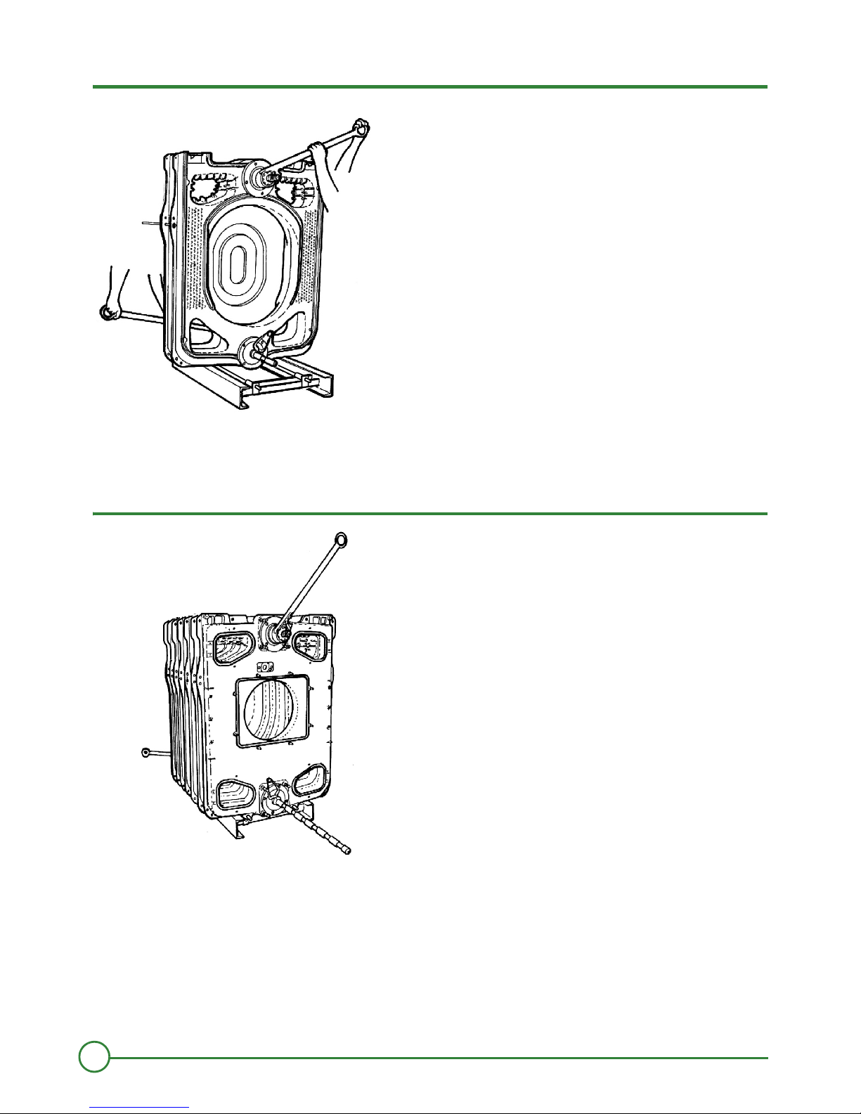
8
` Fill the bottom of the W groove opposite the U groove for the intermediary parts (located on the periphery of the section) with a continuous
bead of DOW CORNING silicon, diameter approximately Ø 5 mm.
9
Rear section
Intermediate section
` Place the first normal intermediate section, making sure that it is turned in the right direction, i.e. with the flattening groove against the
thermocord.
` For safety, insert a lateral assembly rod (supplied) in the holes of the 2 sections.
` Push the section gently and simultaneously on the 2 nipples of the rear section with a hammer and a piece of wood positioned in line with
the bores.
100
100
010
010
M000063
a
M000064
1
2
12
PK 550 18/03/2016 - 300020196-02
2. Mounting PK 550
10
` Put the assembly tool in position.
` Tighten gradually so as to bring together the upper and lower connections evenly and simultaneously.
11
` Assemble the remaining intermediate sections one by one, to the procedure stated in figures 3, 4, 5, 6, 7, 8, 9,, and 10.
` First assemble the normal intermediate sections, then the special ones.
Leave the assembly tool in place.
M000065
M000066
13
18/03/2016 - 300020196-02 PK 550
2. Mounting PK 550
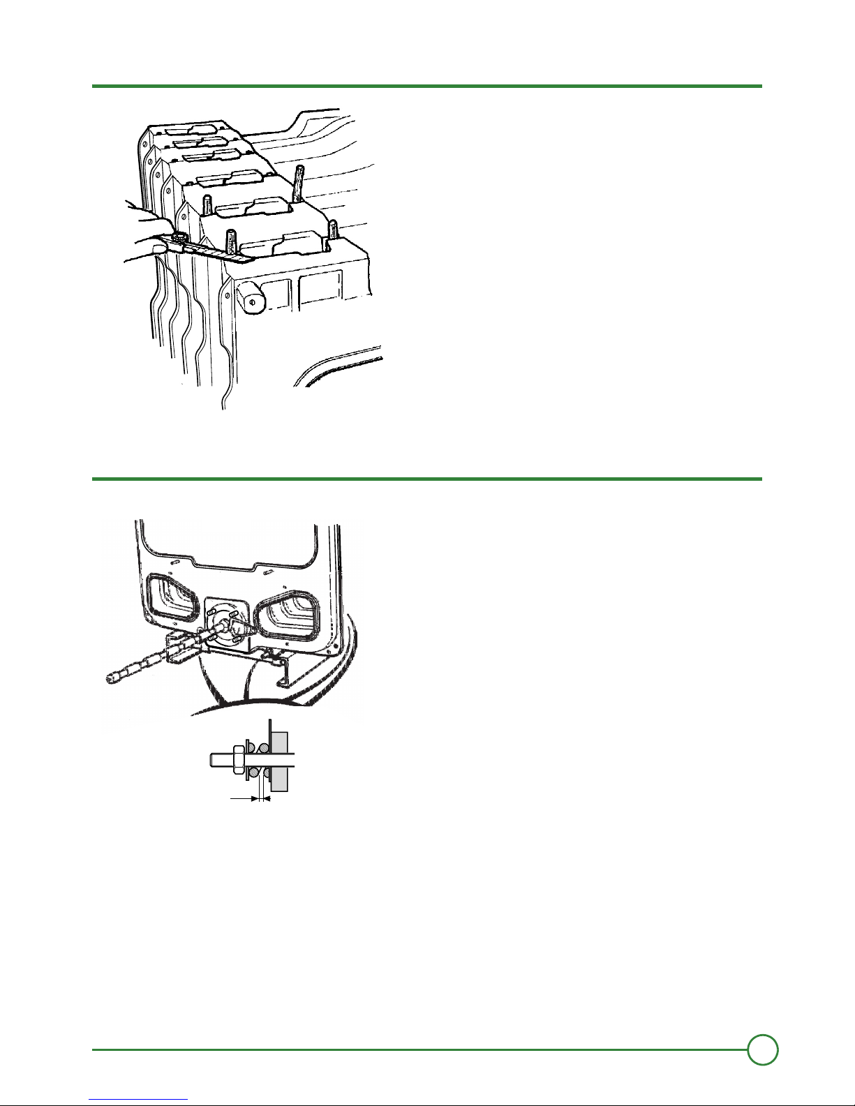
12
` Trim off any projecting ends of the thermocords the sweeping covers.
13
Fitting the upper and lower assembly rods
` On the lower assembly rods, fit the following at each end in the given order : an expansion spring, a washer and a nut (the holes of the
front lugs must be aligned with the holes of the frame brackets as the assembly rods are used to make the boiler body integral with the
frame).
` Stop tightening as soon as the gap between the spring spires is equal to about 2 mm.
M000067
M06000 8
2
14
PK 550 18/03/2016 - 300020196-02
2. Mounting PK 550
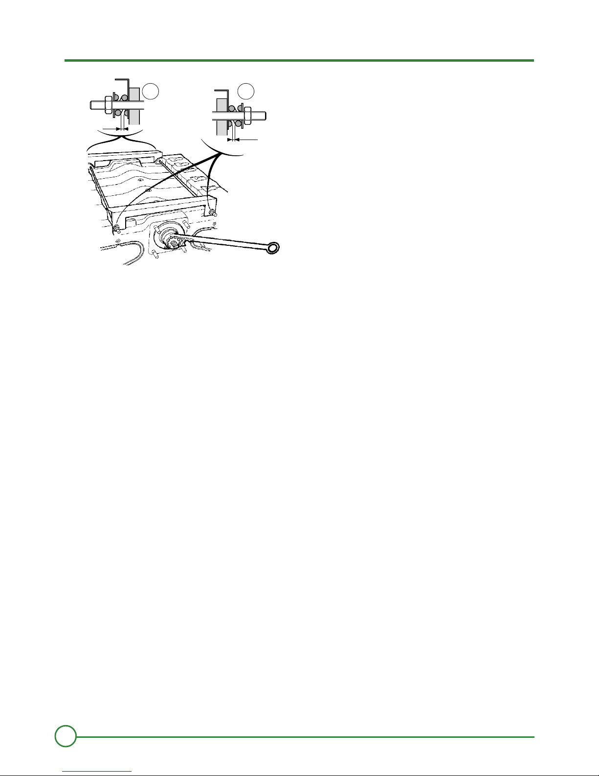
14
Rear
Front
` Put in place the upper assembly rods in the two front and rear lugs.
` Mount the 2 crosspieces (supplied in package MS1/MS2) with their bends turned backwards and fasten them to the rods with an
expansion spring, 1 nut and 1 washer
` Remove the assembly tool.
00069M0
2
2
21
15
18/03/2016 - 300020196-02 PK 550
2. Mounting PK 550
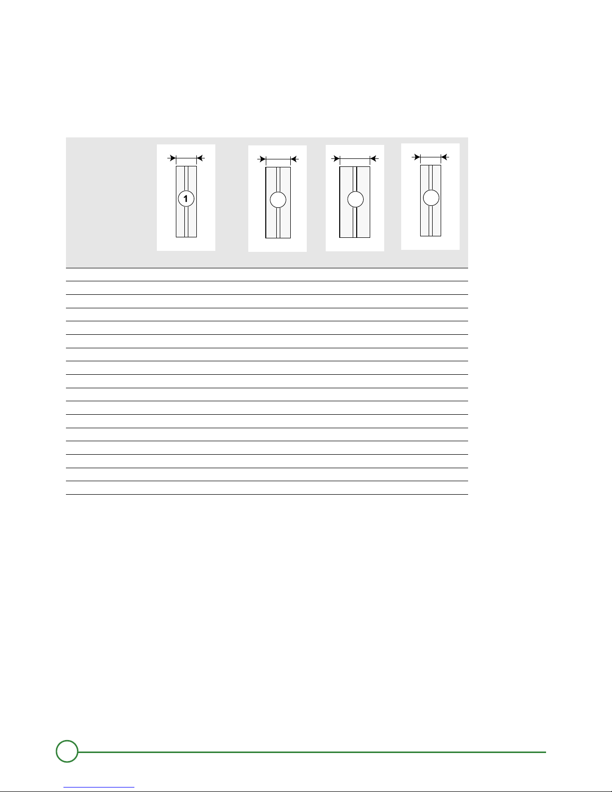
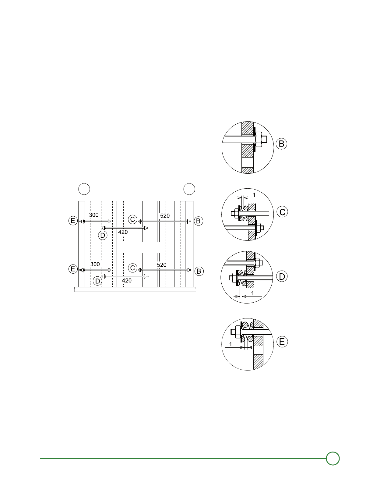
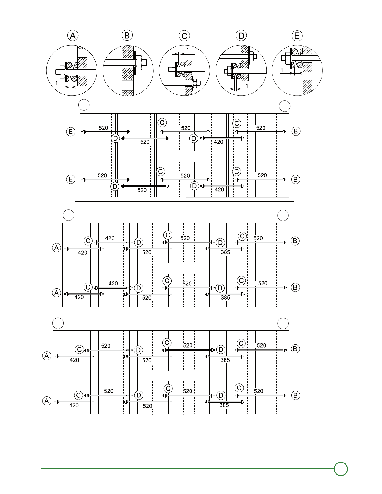
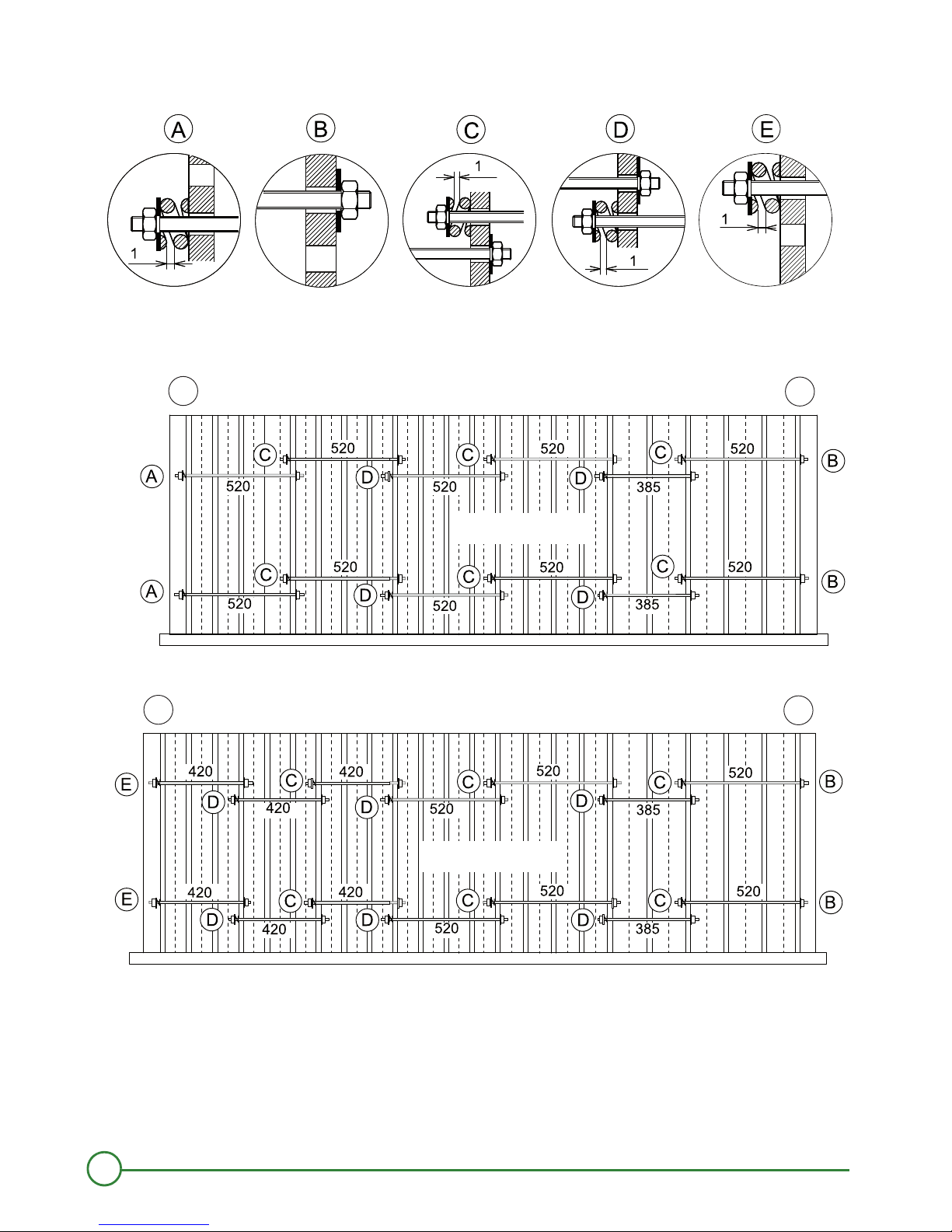
Assembling the side assembly rods
The side assembly rods must be assembled from the rear to the front.
The rods must be inserted in the holes stated in the diagrams (the lugs of the sections in which the assembly rods are to be
inserted have 2 holes).
` Place the expansion spring and washer on the rear of each rod.
` Stop tightening the nuts as soon as the gap between the spires of the springs is about 1 mm
Rear
Front
Dimensions are given in millimeters.
D000915A
1
2
PK550-9
16
PK 550 18/03/2016 - 300020196-02
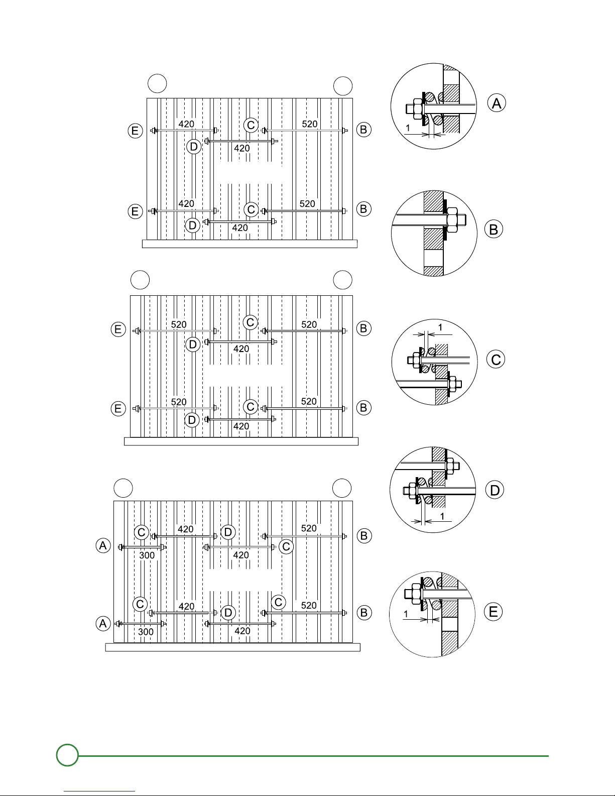
2. Mounting PK 550
Rear
Front
Dimensions are given in millimeters.
PK550-10
PK550-11
PK550-12
D000916A
1
2
1
2
1
2
17
18/03/2016 - 300020196-02 PK 550
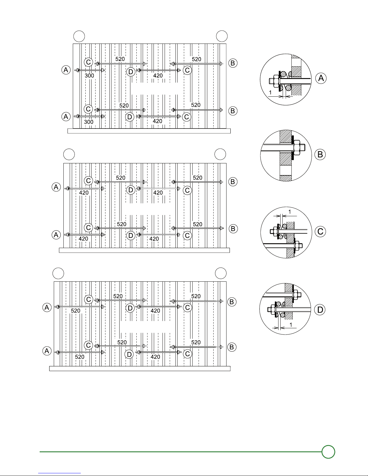
2. Mounting PK 550
Rear
Front
Dimensions are given in millimeters.
PK550-13
PK550-14
PK550-15
D000917A
1
2
1
2
1
2
18
PK 550 18/03/2016 - 300020196-02
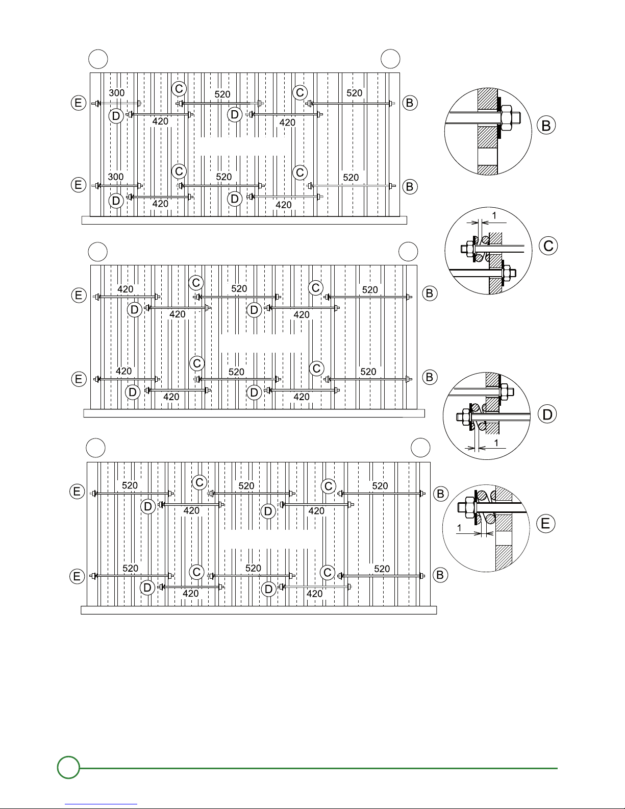
2. Mounting PK 550
Rear
Front
Dimensions are given in millimeters.
PK550-16
PK550-17
PK550-18
D000918A
1
2
1
2
1
2
19
18/03/2016 - 300020196-02 PK 550
2. Mounting PK 550
Rear
Front
Dimensions are given in millimeters.
PK550-19
PK550-20
PK550-21
D000919A
2
1
2
1
2
1
20
PK 550 18/03/2016 - 300020196-02
2. Mounting PK 550
Rear
Front
Dimensions are given in millimeters.
PK550-22
PK550-23
D000920A
2
1
2
1
 Loading...