

Page 1

Operating Instructions
OS3 Vitrex VC830201
VV016031E
0297
29.05.09 VV016031E 1
Page 2

Instructions for using the Oertli OS3 VC830201 Vitrex Module
Contents Page
1 Application and description.........................................................................................................3
2 Important points and hazards .....................................................................................................3
3 The control panel ........................................................................................................................4
3.1 Arrangement of control and indicator elements..........................................................................4
4 Foot switch and pedal.................................................................................................................5
4.1 Foot-operated switch (stand-alone operation) ............................................................................5
4.2 Duallinear pedal (interconnected operation)...............................................................................5
5 Supply connections / power on-off..............................................................................................5
5.1 Compressed air connection ........................................................................................................5
5.2 Electrical connection ...................................................................................................................5
5.3 Replacing fuses...........................................................................................................................5
6 Operation ....................................................................................................................................5
6.1 AIR ..............................................................................................................................................5
6.2 VISCO.........................................................................................................................................6
6.3 LUM light source .........................................................................................................................6
6.3.1 Changing lamps ..........................................................................................................................7
7 ParaProg settings........................................................................................................................7
8 System communication...............................................................................................................7
8.1 Visual displays ............................................................................................................................7
8.2 Acoustic signals ..........................................................................................................................7
8.3 Voice confirmation.......................................................................................................................7
9 Choice of set values....................................................................................................................7
10 Cleaning and sterilisation instructions.........................................................................................7
10.1 Cleaning......................................................................................................................................8
10.2 Sterilisation..................................................................................................................................8
11 Accessories and replacement parts............................................................................................8
12 Authorised service centres..........................................................................................................8
13 Technical data.............................................................................................................................8
14 Overview of messages, warnings and error messages..............................................................9
15 Explanation of symbols...............................................................................................................10
16 Calibration and maintenance ......................................................................................................10
17 Disposal ......................................................................................................................................10
18 OS3 Vitrex VC830201, Overview................................................................................................11
29.05.09 VV016031E 2
Page 3

1 Application and description
The OS3 Vitrex operating unit is used for surgical
procedures in the posterior segment of the eye. It can be
used as a stand-alone unit or, preferably, in conjunction
with the OS3 VC830100 base unit.
The functional features offered by the instrument include
inter-ocular lighting, an air pump to maintain inner eye
pressure and a pump for the injection and extraction of
visco-elastic substances.
IMPORTANT!
Alterations and repairs may only be undertaken by persons
authorised by the manufacturer, otherwise the proper
functioning of the unit may be impaired.
CAUTION!
The unit must never be used in areas containing
inflammable anaesthetics!
The unit actuates and controls the accompanying
instrumentation and consumable materials within the
performance limit values selected by the operator in each
case, and as set on the control panel. A foot pedal is used
for the fine adjustment of these values within the specified
range. The unit is extremely easy to operate. Frequently
used settings can be stored and recalled.
The unit may only be used with the Oertli instruments and
consumable materials recommended and supplied by the
manufacturer (see Section 11).
The unit may only be operated by trained personnel. The
surgeon is responsible for defining the correct settings.
The unit is not suitable for surgical interventions outside the
eye. If in doubt, please contact the manufacturer.
2 Important points and hazards
IMPORTANT!
Please read these instructions very carefully before using
the apparatus for the first time!
IMPORTANT!
When setting up the unit, ensure that neither the rear
ventilation holes nor the top of the unit are covered.
CAUTION!
Never look directly into the lamps when they are lit!
IMPORTANT!
Mobile telephones and other appliances that use radio
frequencies may cause unexpected or undesirable
behaviour of the unit or system!
IMPORTANT!
Never place the unit or system next to or on top of other
appliances when operating it. If it is necessary to arrange
the appliances in this way, it must be checked in each case
that the unit or system is working correctly.
NOTE!
In order to avoid the risk of electric shock, this unit may
only be connected to mains supplies with a protective earth
connection.
IMPORTANT!
The user is responsible for ensuring compliance with and
fulfilment of IEC 60601-1
IMPORTANT!
Before connecting the unit, check that the voltage shown
on the rating plate is the same as that of the operating
room!
CAUTION!
The Visco instrument connections (INJCT and EXTR) must
never come into direct contact with the eye! If a syringe is
to be used as a silicone container, care must be taken to
ensure that there is no air in the syringe reservoir!
IMPORTANT!
While in the EXTR mode, ensure that liquid is never sucked
into the unit at the Visco instrument connection, especially
during the application of substances with a lower viscosity.
IMPORTANT!
The correct choice of equipment settings is the
responsibility of the surgeon!
Settings given in this instruction manual are suggestions
only.
IMPORTANT!
Only those instruments and accessories supplied by the
manufacturer and listed in Section 11 may be used!
29.05.09 VV016031E 3
Page 4
The control panel
40 mmHg
0.50 bar
0.10 bar
All settings for operating the OS3 Vitrex unit can be entered
on the control panel (pre-settings are entered in ParaProg,
see Section 7). A visual display shows at a glance the
operating state of the system and the current values.
The buttons respond to gentle pressure which can also be
applied either with a sterile swab or the sterile operating
pen (VE850003) available from the manufacturer.
Depending on the stage of the operation or the position of
the control pedal, certain buttons will be disabled. This
feature offers increased protection against improper use.
The execution of a command is accompanied by
corresponding changes in the display field. If a disabled
button is pressed, no change is shown on the display.
The control panel cannot be separated from the unit. If you
are using it in combination with the OS3 VC830100 base
unit, a VE830020 remote controller can be attached.
2.1 Arrangement of control and indicator elements
Diplay and
setting area
Function
selection area
Injection pressure indicator
Displays the selected limit value (current value flashes
when active) of the injection pressure at the VISCO (B)
outlet. The unit of measurement can be set using ParaProg
(mmHg, PSI, kPa).
Extraction vacuum indicator
Displays the selected limit value (current value flashes
when active) of the extraction vacuum at the VISCO (B)
outlet. The unit of measurement can be set using ParaProg
(mmHg, PSI, kPa).
Arrow buttons
The arrow buttons can be used to reduce (down arrow) or
increase (up arrow) the value shown in the display field
immediately above. Exert normal pressure to change the
value slowly or in individual increments, or fully depress for
rapid value setting.
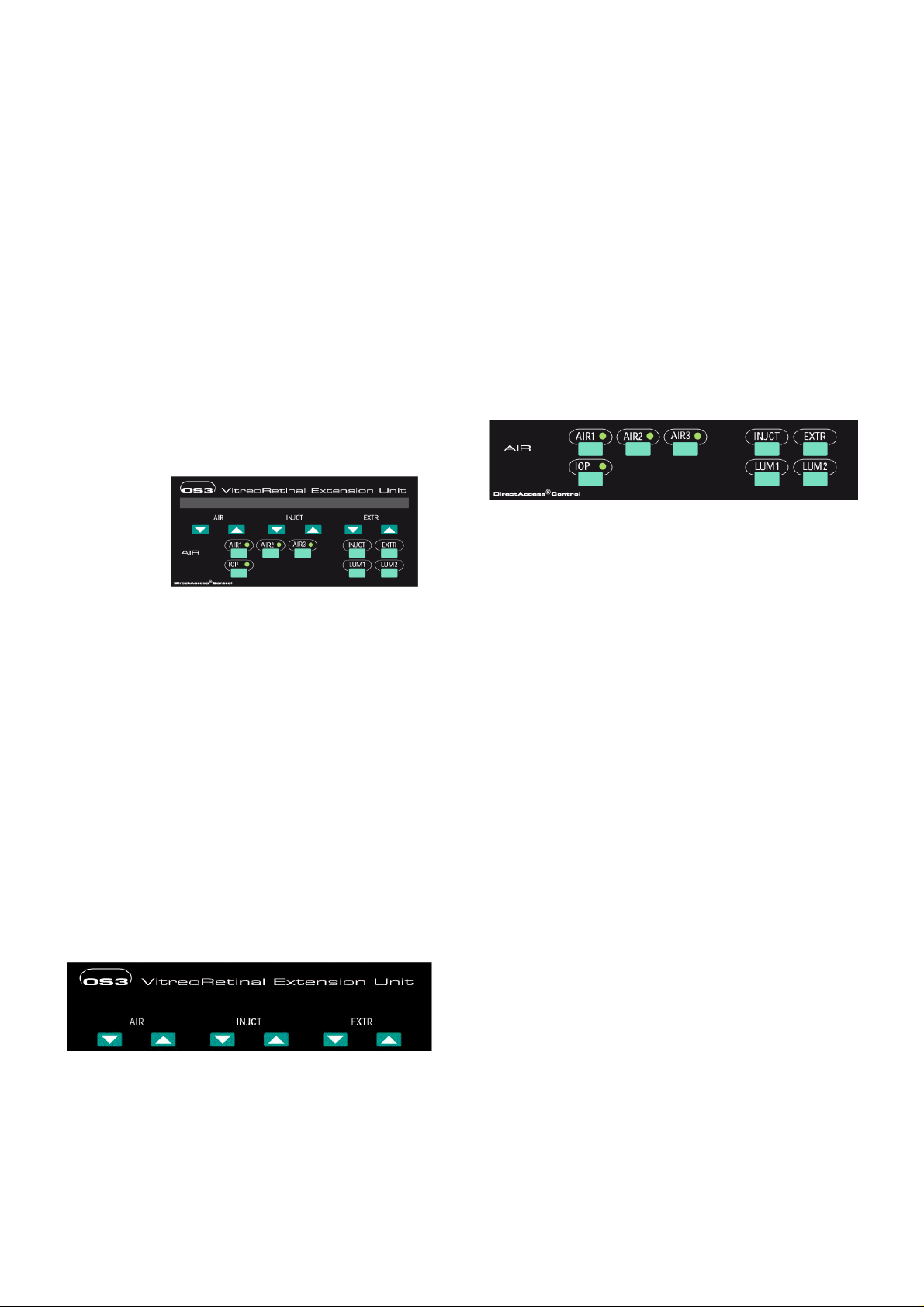
The function selection area
AIR1 button and indicator light
Activates the AIR function with the pressure value stored in
memory 1. The indicator lamp lights up.
Press again to activate the pump and reduce pressure.
Pressing once more will deactivate the pump and the
function and switch off the indicator lamp.
The control and indicator elements are grouped in such a
way that they can be operated after only a short period of
familiarisation, even in semi-darkness. The top half of the
control panel is the indicator and setting area. It is designed
to show at a glance the operating state of the unit and the
current values. The values displayed can be increased or
reduced using the dark green arrow buttons directly below
the value displays.
The lower half of the control panel houses the function
selection buttons.
Please familiarise yourself thoroughly with this ergonomic
arrangement of the control elements; it will enable you to
operate the equipment quickly almost "blind"!
The display and setting area
Air pressure indicator Injection pressure Extraction vacuum
indicator Indicator
Air pressure indicator
Displays the selected limit value (current value flashes
when active) of the air pressure at the AIR (A) outlet. The
unit of measurement can be set using ParaProg (mmHg,
PSI, kPa).
AIR2 button and indicator light
Activates the AIR function with the pressure value stored in
memory 2. The indicator lamp lights up.
Press again to activate the pump and reduce pressure.
Pressing once more will deactivate the pump and the
function and switch off the indicator lamp.
AIR3 button and indicator light
Activates the AIR function with the pressure value stored in
memory 3. The indicator lamp lights up.
Press again to activate the pump and reduce pressure.
Pressing once more will deactivate the pump and the
function and switch off the indicator lamp.
INJCT button
Activates the Visco injection function with the limit value
last used for the injection pressure. Press again to switch
off the function.
EXTR button
Activates the Visco extraction function with the limit value
last used for the extraction vacuum. Press again to switch
off the function.
IOP button and indicator light
Enables the control of AIR functions via a duallinear pedal
(illuminated display) when operated in combination with the
OS3 VC830100 base unit
When the unit is operated in stand-alone mode this button
has no function.
29.05.09 VV016031E 4
Page 5

LUM1 button
QOP
Switches the left-hand light source (LUM1) on and off.
If no pressure is detected, the message "CHECK
COMPRESSED AIR!" appears.
LUM2 button
Switches the right-hand light source (LUM2) on and off.
Note: If the light source is ON the display shows an
asterisks * between the values for Extraction and Injection
3 Foot switch and pedal
When used as a stand-alone unit, pneumatic foot switches
control the Vitrex. When used in combination with the OS3
VC830100 base unit, it is controlled by the duallinear pedal.
3.1 Foot-operated switch (stand-alone operation)
The hoses for the pneumatic foot-operated switches INJCT
(no. 1), EXTR (no. 2) and AIR (no. 3) can be inserted into
the rear of the Vitrex unit. Ensure that the foot-operated
switches are not depressed whilst the hoses are being
inserted.
3.2 Duallinear pedal (interconnected operation)
In interconnected operation, the INJCT, EXTR and AIR
functions can be controlled by the duallinear pedal. See
operating instructions VV016011D for the OS3 base unit.
4 Supply connections / power on-off
4.1 Compressed air connection
Connect the compressed air connector K to the
compressed air network using a NIST EN 397 air fitting
(VX100911).
IMPORTANT!
The compressed air supply must have a pressure of 6.5 –
10 bar!
NOTE: The LUM (light) and AIR functions can be operated
even without a pressure connection.
4.2 Electrical connection
IMPORTANT!
The mains supply voltage in the operating area must be
100 - 240 V AC / 50 - 60 Hz!
After a successful test, the message "SYSTEM READY!"
appears, and the installed software version is displayed in
weakly illuminated lettering.
The unit is now ready and can be prepared for the
operation.
4.3 Replacing fuses
Press clip on fuse holder P to the right, until it pops out.
Use a small screw driver if need be. Fully pull out holder.
Insert new fuse and push holder P back in again.
The correct fuse value is printed above the holder P on the
rear panel of the unit.
5 Operation
5.1 AIR
Connect an air delivery line with filter (VV690100) or an
alternative Oertli original air feed accessory (see Section
11) to the AIR (A) port. Observe the instructions on the
packaging note.
IMPORTANT!
Only Oertli original accessories should be used. A filter
should always be attached to the AIR port. Accessories
must not be re-used!
Press one of the buttons AIR1, AIR2 or AIR3. The stored
pressure value and the indicator lamp for the respective
memory will light up in the air pressure display field.
Use the arrow button to change the pressure value. The
range is 1-120 mmHg, unless otherwise limited in
ParaProg.
The air supply can be switched on and off in the following
ways:
With the active (light indicator) AIR1, 2, 3 button
With the AIR foot switch (pneumatic)
With the TOP right pedal switch1), if used in
conjunction with the OS3 base unit
With the active AIR1, 2, 3 button (light indicator) on the
remote controller if used in conjunction with the base
unit.
1)
If specified in ParaProg for the base unit
NOTE: If the Vitrex unit is in standby or System Ready
mode, the AIR1 function will be switched on just by
activating the foot switch or the TOP right switch.
Plug the supplied mains cable into the mains connection
socket O (on the rear panel of the unit), and connect to the
mains supply socket.
Set the mains switch Q to position I.
As soon as it is switched on, the unit performs an autotest
to check the functioning of the circuits, voltages and
pressure system.
The display will flash continuously while the air supply is
active, and it is possible to change between memories
AIR1, AIR2 or AIR3 at any time.
The AIR function can be operated in parallel with all of the
other functions of the OS3 system (Vitrex and base unit).
IOP function (only in interconnected operation)
When the IOP button is active (indicator light on), air
pressure can be changed using the HEEL switches of the
duallinear pedal (stepless, or by changing between AIR 1,
2 and 3, depending on the ParaProg setting). The air
pressure is shown in the display for the bottle height (OS3
29.05.09 VV016031E 5
Page 6

operating panel), and the corresponding arrow buttons are
functional.
The IOP function is used mainly in conjunction with the
accessories for active infusion.
Warning tone
An alarm threshold for the pressure value can be defined in
ParaProg (Section 7). When the specified pressure value is
reached, an alarm tone sounds regardless of memory
AIR1, 2 or 3.
Storing values
Press the desired button AIR1, 2 or 3. Set the pressure to
the required value using the arrow buttons. Hold down the
active button AIR1, 2 or 3 until "VALUE SET" appears. If
the button is not depressed long enough, "NOT SET" will
appear.
NOTE: When used in conjunction with the OS3 base unit,
the value stored will apply only for the surgeon whose
number has been entered.
5.2 VISCO
Connect a silicone application set, VV690210 or VV690211
or other Oertli original Visco accessory to the VISCO (B)
port. Observe the instructions on the packaging note
precisely.
IMPORTANT!
Only Oertli original accessories should be used. Always
attach the VISCO connection to an infusion syringe, and
never bring it into direct contact with the eye!
INJCT/EXTR function
Both the INJCT and EXTR functions can be operated
simultaneously. Press the INJCT and EXTR buttons to do
this. When using the duallinear pedal, INJCT is to the left
and EXTR to the right.
NOTE: In interconnected operation with the OS3 base unit,
the aspiration function may also be operated during the
INJCT and EXTR function. To do this, set the required flow
rate (venturi rate) and aspiration vacuum on the base unit.
The values used last will appear. To aspirate, move the
duallinear pedal to position 2.
5.3 LUM light source
IMPORTANT!
Never operate the light source with the cover open – risk of
being dazzled!
Always connect a light instrument to the light output before
switching on to avoid being dazzled!
Never use light instruments with other connectors and
never push foreign objects into the light output socket.
Reduce the brightness using the rotary knob before
switching on.
Connect a light instrument with Oertli original light
connector to each of the light outputs LUM1 and LUM2.
INJCT function
Press the INJCT button. The value used last appears in the
injection pressure display field (surgeon-specific in
interconnected operation). Use the arrow buttons to change
the pressure value. The range is 0.05 – 5.0 bar unless
otherwise limited in ParaProg (Section 7).
The injection pressure is switched on or off by pressing the
pneumatic foot switch (left). The display will flash and an
acoustic signal will sound. When used in conjunction with
the OS3 base unit, the injection pressure is regulated
linearly by moving the duallinear pedal to the left or right.
To exit the INJCT function, press the INJCT button or, in
interconnected operation, a function button on the OS3
base unit.
EXTR function
Press the EXTR button. The value used last appears in the
extraction vacuum display field (surgeon-specific in
interconnected operation). Use the arrow buttons to change
the vacuum value. The range is 0.01 – 1.0 bar unless
otherwise limited in ParaProg (Section 7).
The extraction vacuum is switched on or off by pressing the
pneumatic foot switch (right). The display will flash and an
acoustic signal will sound. When used in conjunction with
the OS3 base unit, the vacuum value is regulated linearly
by moving the duallinear pedal to the left or right.
The VX100940 adapter can be used to connect disposable
light instruments.
The light source is suitable for both disposable and
autoclavable light instruments.
Insert the light instrument into the connection socket until
fully engaged.
Switch on the lamps with the LUM1 and LUM2 buttons. To
switch off, press the respective button again. The cooling
fan will continue to run for a time.
The desired brightness can be set smoothly using the
rotary knobs for light dimming. The two light sources are
independent of each other.
NOTE: Hot lamps must be allowed to cool down before
they can be switched on again. The cooling time is around
30 seconds. A message will appear if an attempt is made
to switch on the lamp again within this period of time.
NOTE: If a lamp begins to flicker during operation, it has
reached the end of its service lifetime. The lamp must be
replaced before the next operation.
NOTE: if both lamps fail to light up, switch the unit off for at
least 15 seconds. Then try again to light the lamps.
To exit the EXTR function, press the EXTR button or, in
interconnected operation, a function button on the OS3
base unit.
29.05.09 VV016031E 6
Page 7

5.3.1 Changing lamps
If a lamp does not light up after frequent attempts to do so
or does not light up at all within one minute, it has reached
the end of its service life and must be replaced.
Allow the unit to cool until the fan switches off, then
switch off the mains switch Q.
Remove the middle screw from the sliding cover.
Open the sliding cover on top of the unit in the
direction of the arrow.
Remove the clamping screw next to the socket and
separate the plug halves.
Pull out the socket together with the lamp and insert a
new lamp.
Insert the clamping screw and connect the plug halves
together.
IMPORTANT!
- Risk of burns
- Do not touch the metal halide lamps with your bare hand!
Hold the lamp by the metal socket only. Use only original
VV300004 lamps.
6 ParaProg settings
Several important basic settings can be entered in the
ParaProg. These settings only affect the Vitrex unit, and
have nothing to do with the ParaProg settings for the OS3
base unit. However, if the Vitrex unit is being used in
conjunction with the OS3 base unit, the ParaProg settings
will apply only for the surgeon selected in the base unit.
The respective parameter appears in the AIR display field.
Selectable options are shown in the INJCT field. The
Illuminated value is the one previously selected; the
flashing value may be selected by pressing the ↵ -button.
To exit ParaProg, press the AIR1 function button.
7 System communication
7.1 Visual displays
Selected, stored and current values and important
information about the status of the unit are indicated by
light displays on the control panel. Warnings and
instructions appear in the language selected in ParaProg.
See Section 7.
7.2 Acoustic signals
The unit uses acoustic signals to inform you about the
generation of vacuum and pressure.
INJCT pressure: slow repeating beep tone
EXTR vacuum: slow repeating high/low acoustic signal
Volume control
The volume can be set between 0 - 100 % in ParaProg.
The volume is not surgeon-specific when used in
combination with the OS3 base unit.
7.3 Voice confirmation
If the unit is being operated in conjunction with the OS3
base unit, the voice confirmation function of the OS3 base
unit will also include the Vitrex unit. See operating
instructions VV016011D for the OS3 base unit for detailed
information.
IMPORTANT!
For ParaProg settings in interconnected operation, it is
essential that the surgeon number in the base unit is
observed!
To access the ParaProg function, switch off the Vitrex unit
at the mains switch Q Then press and hold down the
INJCT button whilst switching on the mains switch Q again.
Release the INJCT button as soon as "ParaProg" is
displayed.
ParaProg Vitrex
To page forward in the program, press the ↓ button.
Alternatively, the arrow buttons beneath AIR can be used
to page forwards or backwards.
The ParaProg parameters are defined in the VV016032D
appendix. Make sure that they agree with the installed
software.
UnitAIR mmHg
8 Choice of set values
Every surgeon develops his own preferred operating
technique, which also requires specific set values for the
various stages of the operation.
The OS3 unit enables a high level of compatibility with
these individual requirements.
The unit is supplied with the values set during the last trial
or internal works test. These values are certainly not
recommended or suggested values. The correct choice of
equipment settings is the responsibility of the surgeon!
Please also note that set values cannot necessarily be
transferred from other makes of operating equipment to the
OS3 unit.
As a general principle, we recommend that you work
initially with moderate set values.
Our sales consultants will be pleased to advise you on the
basis of our experience during the trial and induction
period.
9 Cleaning and sterilisation instructions
IMPORTANT!
Under no circumstances may accessories for air supply,
active infusion and visco application be reused!
29.05.09 VV016031E 7
Page 8

9.1 Cleaning
Autoclavable light instruments must be immersed in BSS or
distilled water and thoroughly rinsed immediately after the
operation!
The cleaning instructions supplied with the instruments
should be strictly observed!
Consumable material, AIR/VISCO (disposable)
VV690100 Air delivery line with filter, pack of 10
VV690110 Air application set for IOP control, anterior
VV690111 Air application set for IOP control, posterior
VV690210 Silicone application set, 20 cc, pack of 10
VV690211 Silicone application set, Opsia, pack of 10
Use only distilled or de-ionised water, neutral detergents
and a soft lint-free cloth or a soft sponge!
Ensure that all instruments are free of blood, tissue and
impurities caused by saline deposits or other substances.
Rinse carefully and thoroughly with distilled water, and
carefully clean with compressed air.
Do not use oxygen or other gases!
9.2 Sterilisation
Steam sterilisation is the prescribed method for light
instruments. ETO sterilisation is not recommended, and
gamma sterilisation is not permitted owing to the instability
of the materials!
IMPORTANT!
The user is responsible for the proper application of
sterilisation methods including precautions taken to ensure
bacteriological safety.
After cleaning (as described in Section 10.1), the
instruments must be sterilised in the autoclave with the
supporting air extraction device.
The recommended values are: temperature 134°C - 138°C,
minimum cycle duration of 3 minutes.
When the instruments are removed from the sterilisation
unit, they should be cooled to room temperature before
operating.
IMPORTANT!
Instruments must always be sterilised before every use!
10 Accessories and replacement parts
IMPORTANT!
The use of accessories other than those listed, or of other
converters and cables may lead to increased interference
emission or reduced interference immunity of the unit or
system!
IMPORTANT!
Accessories, converters and cables are listed in the
following table for which the manufacturer guarantees EMC
compatibility!
Consumable material, light (disposable)
VV300101 Endo illuminator, straight, pack of 10,
microconnection
VV300131 Endo illuminator, 30°, pack of 10,
microconnection
VV300201 Endo illuminator with microhook, pack of 10,
micro-connection
Light instruments, autoclavable
VE201728 Endo illuminator with diathermy, "plug-on"
VE301005 Endo illuminator with microhook, 2 m cable
VE302003 Light sleeve for SDS instruments, 1.6 mm
VE302004 Light sleeve for SUS instruments, 1.6 mm
VE308130 Endo illuminator, 30°, 2 m cable
VE308160 Endo illuminator, 60°, 2 m cable
VE308190 Endo illuminator, straight, 2 m cable
11 Authorised service centres
Switzerland Oertli Instrumente AG
(Manufacturer) Hafnerwisenstr. 4
CH–9442 Berneck
Phone: +41–71–7474200
Germany Domilens GmbH
Holsteiner Chaussee 303a
D–22457 Hamburg
Phone: +49–40–5598800
Austria Mositech GmbH
Schwefel 93
A–6850 Dornbirn
Phone: +43–5572–34534
Information about other service centres can be obtained
from the manufacturer.
Authorised representative in the EU
Germany Oertli Instrumente GmbH
Magnolienweg 14
D–63741 Aschaffenburg
Unit accessories
VC830100 OS3 base unit
VE830001 Unit trolley with infusion pole drive
VE830010 Programmable duallinear pedal
VE830020 Remote control with illumination
VX100940 Light adapter for disposable leads
VX100907 Pneumatic foot switch AIR
VX100908 Pneumatic foot switch INJCT/EXTR (VISCO)
VX100911 Pressure hose with NIST air connection
VX100912 OS3/Vitrex pneumatic connection cable
VX100913 OS3/Vitrex COM connection cable
VV300004 Replacement metal halide lamps
VX520010 3.15 AT fuses, high breaking capacity
12 Technical data
Supply pressure* Air 6.5 - 10 bar, max. 25l/min
NIST EN-739 connection
Supply voltage 100 – 240 V AC
Supply voltage frequency 50 – 60 Hz
Power consumption 320 VA
Fuses 3.15 AT, high breaking
capacity
Operating mode continuous
Application parts non-electrically powered
Protection class I
CE classification IIb
Visco injection 0.05 - 5 bar ±0.2 bar
Visco extraction 0.01 - 1 bar ±0.05 bar
Air pump 1 - 120 mmHg ±10 mmHg
29.05.09 VV016031E 8
Page 9

Light Metal halide
24 V/21 W
2 x 1460 Lumen
Noise emission < 70 dB (A)
Dimensions 380 x 110 x 340 mm (W/H/D)
Weight 8.7 kg
Transport and Temperature 20°C - +55°C
storage conditions Atmos. pressure 500hPa -
1060hPa
Relative humidity
10% - 95%
non-condensing
Operating conditions Temperature 10°C - 35°C
Atmos. pressure 700hPa -
1060hPa
Relative humidity 20% - 80%
non-condensing
*If there is no compressed air connection, the INJCT and EXTR functions
cannot be operated
13 Overview of messages, warnings and error
messages
Pressure deviation
The actual value deviates considerably from the desired
value.
Automatic safety venting.
No pressure
Pressure at the compressed air connection is too low.
Check supply pressure (min. 6.5 bar).
Not set.
Values were not stored.
System ready
The autotest has been successfully completed.
Values set
Values were stored.
Set values
Values will be stored.
Temperature too high
Allow the light to cool.
Replace lamp 1
Lamp 1 is defective, replace it.
Replace lamp 2
Lamp 2 is defective, replace it.
Call Service Error 101
Call service (internal voltages defective).
Unit cannot be operated.
Adjust Unit Error 102
Call service (pressure measurement incorrect).
Unit cannot be operated.
Extr Deviation Error 103
Pressure instead of vacuum.
Call service.
HW Lum Error 104
Incorrect light source set.
Call service.
29.05.09 VV016031E 9
Page 10

14 Explanation of symbols
COM
Use only mains fuses with the specified
value
Risk of burns!
Follow the operating Instructions
Dangerous voltages.
Do not open the unit!
Footswitch connection
Grounding pin
Operating Instructions
WEEE – have the appliance disposed of
correctly
Connection for communication with OS3
base unit
15 Calibration and maintenance
The unit requires the following calibration and
maintenance:
Yearly calibration:
Adjustment of the pressure sensor as described in the
service manual
Yearly maintenance:
Checking of electrical cables (instrument and power
leads) for signs of wear and tear, and replacement as
necessary.
16 Disposal
This unit should be disposed of in accordance with local
regulations for the disposal of electronic equipment, or it
should be returned to the manufacturer for disposal.
Items designed for single use should be disposed of in
accordance with local regulations for the disposal of
contaminated medical waste.
Instruments for repair should be cleaned and sterilised prior
to their return to the service centre.
29.05.09 VV016031E 10
Page 11

17 OS3 Vitrex VC830201, Overview
Front view
Rear view
A Air hose connection (air pump)
B Visco application set connection (INJCT/EXTR)
C Light cable connections (Oertli standard)
D Rotary knobs for light dimming
E Sliding cover for replacing lamps
F Control panel
G Connection for injection footswitch
H Connection for extraction footswitch
J Connection for air footswitch
K Compressed air connection (see service manual)
L Slot for smart card (see service manual)
M Connection for data cable to the base module
N Grounding pin
O Mains connection socket
P Fuse holder
Q Mains switch
29.05.09 VV016031E 11
Page 12

Table 201:
Guidelines and manufacturer’s declaration – electromagnetic compatibility
The unit is intended for operation in the electromagnetic environment described below. The customer or the user of the
unit should ensure that it is used in such an environment.
Emission measurement Conformity Electromagnetic environment - guidelines
HF emissions
according to CISPR 11
HF emissions according to
CISPR 11
Group 1 The unit uses HF energy exclusively for its own
internal functions. Its HF emission level is therefore
very low and it is unlikely that adjacent electronic
equipment will be affected.
Class B The unit is intended for use in all facilities including
residential areas and those directly connected to
public supply networks that also supply residential
buildings.
Table 202:
Guidelines and manufacturer’s declaration – electromagnetic immunity
The unit is intended for operation in the electromagnetic environment described below. The customer or the user of the unit
should ensure that it is used in such an environment.
Immunity
tests
Electrostatic discharge
(ESD)
according to IEC 610004-2
Fast transient electrical
interference
variables/bursts according
to IEC 61000-4-4
Surge voltages
(Surges)
according to IEC 610004-5
Voltage drops, short
interruptions and
fluctuations of the supply
voltage
according to IEC 610004-11
Magnetic field at the
mains supply frequency
according to IEC 610004-8
NOTE: UTis the mains AC voltage before application of the test level
IEC 60601
Conformity level Electromagnetic environment - guidelines
test level
± 6kV
contact discharge
± 6kV
contact discharge
Floor should be made of wood or concrete or
covered by ceramic tiles. If the floor is
covered with synthetic material, the relative
± 8kV
air discharge
± 2kV
for mains cable
± 8kV
air discharge
± 2kV
for mains cable
humidity must be at least 30 %.
The quality of the supply voltage should be
equivalent to that in a typical commercial or
hospital environment.
± 1kV
for input and output
cables
± 1kV
voltage external
conductor – external
conductor
± 2kV
voltage external
conductor – earth
< 5 % U
T
for ½ cycle
(> 95 % drop)
40 % U
T
for 5 cycles
(60 % drop)
70 % U
T
for 25 cycles
(30 % drop)
< 5 % U
T
for 5 sec.
(> 95 % drop)
± 1kV
for input and output
cables
± 1kV
voltage external
conductor – external
conductor
± 2kV
voltage external
conductor – earth
< 5 % U
T
for ½ cycle
(> 95 % drop)
40 % U
T
for 5 cycles
(60 % drop)
70 % U
T
for 25 cycles
(30 % drop)
< 5 % U
T
for 5 sec.
(> 95 % drop)
The quality of the supply voltage should be
equivalent to that in a typical commercial or
hospital environment.
The quality of the supply voltage should be
equivalent to that in a typical commercial or
hospital environment.
3 A/m 30 A/m Magnetic fields at the rated frequency should
be equivalent to the typical values found in
commercial and hospital environments.
29.05.09 VV016031E 12
Page 13

Table 204:
Guidelines and manufacturer’s declaration – electromagnetic immunity
The unit is intended for operation in the electromagnetic environment described below. The customer or the user of the
unit should ensure that it is used in such an environment.
Immunity
tests
Conducted
HF interference
variables
according to IEC
61000-4-6
Radiated
HF interference
variables
according to IEC
61000-4-3
IEC 60601
test level
3 V eff
150 kHz to 80 MHz
3 V/m
80 MHz to 2.5 GHz
Conformity level Electromagnetic environment - guidelines
Portable and mobile radio devices are not used at a
distance closer to the unit including its cables than
the recommended safe distance calculated by
means of an equation appropriate for the
transmission frequency.
Recommended safe distance:
10 V eff
Pd 35.0
10 V/m
Pd 35.0 80MHz to 800MHz
Pd 70.0 800MHz to 2.5GHz
Where P is the rated power of the transmitter in
Watts (W) according to the transmitter
manufacturer’s specifications and d is the
recommended safe distance in metres (m).
The field strength of all stationary radio transmitters
is less than the conformity levelbfor all frequencies
according to a local examination3.
Table 206:
Recommended safe distances between portable and mobile
HF telecommunication devices and the unit
The unit is intended for operation in the electromagnetic environment described below, in which the HF interference
variables are controlled. The customer or the user of the unit can help to avoid electromagnetic interference by
maintaining the recommended minimum distance between portable and mobile HF telecommunication devices
(transmitters) and the unit as given in the table below according to the maximum output power of the communication
device.
Rated power
of the transmitter (P) W
0.01 0.035 0.035 0.070
0.1 0.11 0.11 0.22
1 0.35 0.35 0.70
10 1.1 1.1 2.2
100 3.5 3.5 7.0
For transmitters whose maximum rated power is not given in the above table, the recommended safe distance d in metres
(m) can be determined using the equation given in the respective column, where P is the maximum rated power of the
transmitter in Watts (W) according to the transmitter manufacturer’s specifications.
NOTE 1 Thehigher value applies at 80 MHz and 800 MHz.
NOTE 2 These guidelines may not apply in all situations. The propagation of electromagnetic waves is affected by
absorption and reflection from buildings, objects and persons.
Safe distance in metres depending on the transmission frequency
150kHz to 80MHz
Pd 35.0
80MHz to 800MHz
Pd 35.0
800MHz to 2.5GHz
Pd 70.0
Interference is possible in the vicinity of equipment
NOTE 1: The higher value applies at 80 MHz and 800 MHz.
NOTE 2: These guidelines may not apply in all situations. The propagation of electromagnetic waves is affected by
a
b
absorption and reflection from buildings, objects and persons.
The field strength of stationary transmitters, e.g. base stations for radio telephones and mobile agricultural broadcast
services, amateur radio stations, AM and FM radio and television transmitters cannot be precisely determined
theoretically in advance. In order to determine the electromagnetic environment resulting from stationary transmitters,
an examination of the location is recommended. If the field strength determined at the location of the unit exceeds the
conformity level stated above, the unit must be observed with regard to its normal operation at each place of use. If
unusual performance characteristics are observed it may be necessary to take additional measures, such as realigning
or moving the unit.
The field strength should be smaller than 10 V/m above the frequency range from 150 kHz to 80 MHz.
bearing the following symbol.
29.05.09 VV016031E 13
 Loading...