

Oerlikon Leybold Vacuum Sogevac SV300 B Operating Instructions Manual

Part Numbers
960 700 to 960 703
960 706 to 960 708
960 711 to 960 713
960 716 to 960 718
Sogevac SV300 B
Single-stage, oil-sealed
Rotary Vane Pump
Operating Instructions GA02330_002_06
Document 300270042/002/06

Important Safety Information 3
1 Description 4
1.1 Design and function 4
1.2 Standard specification 5
1.3 Technical data 6
1.4 Connection fittings 11
1.5 Accessories 12
1.6 Spare parts 13
1.7 Lubricants and grease 13
1.8 Manipulation and stock 13
2 Operation 14
2.1 Installation 14
2.2 Connection to system 14
2.3 Electrical connections 17
2.4 Start-up 19
2.5 Operation 19
2.6 Shutdown 21
2.7 Pump ultimate pressure 21
3 Maintenance 22
3.1 Maintenance schedule 22
3.2 Checking the oil 23
3.3 Oil change, Replacing the Oil Filter 24
3.4 Cleaning the dirt trap 25
3.5 Checking the anti-suckback valve 25
3.6 Cleaning the gas ballast intake filter 26
3.7 Disassembly of electrical motor 26
3.8 Radiator cleaning 26
3.9 Exhaust filter exchange 26
3.10 Heat exchanger cleaning 27
4 Troubleshooting Guide 28
EC Declaration of Conformity
Declaration of contamination
Spare Parts list
Sales and Service
Contents
2 GA02330_002_06 - 01/2010 - © Oerlikon Leybold Vacuum
Page
Important Safety Information
It is mandatory that these operating instructions be read and understood prior
to the vacuum pump installation and start-up.
The SOGEVAC vacuum pumps have been manufactured according to the
newest technical standards and safety regulations. If not installed properly or
not used as directed, dangerous situations or damages might occur.
Under certain operating conditions, dangerous situations may occur when
running the vacuum pump. If this happens, please contact our local office.
Indicate procedures that must be strictly observed to prevent hazards to
persons.
Indicate procedures that must be strictly observed to prevent damage to, or
destruction of the appliance.
The references to figures, e. g. (2/10) consist of the Fig. No. and the item No. in
that order.
We reserve the right to alter the design or any data given in these Operating
Instructions.
When working on the pump system, always observe the Operating Instructions.
Disconnect the unit from the power supply before starting any work. Take
appropriate precautions to ensure that the pump cannot start.
If the pump has pumped hazardous gases, it will be absolutely necessary to
determine the nature of the hazard involved and take the appropriate safety
precautions.
Observe all safety regulations !
Take adequate safety precautions prior to opening the intake or exhaust port.
If you send a pump to Oerlikon Leybold Vacuum, indicate whether the pump
is free of substances damaging to health or whether it is contaminated. If it is
contaminated also indicate the nature of hazard.
For this you must use the form we have prepared and which will be provided
upon request.
A copy of this form, «Declaration of Contamination of Vacuum Instruments and
Components» is reproduced at the end of the Operating Instructions.
Please attach this form to the pump, or enclose it with it. This Declaration is
required to meet the law and to protect our personnel.
Oerlikon Leybold Vacuum will return any pump received without a "Declaration
of Contamination" to the sender's address.
The pump must be packaged in such a way that it will not be damaged during
shipping, and so that no harmful substances can escape from the package.
Safety Information
3
GA02330_002_06 - 01/2010 - © Oerlikon Leybold Vacuum
Warning
Warning
Warning
Caution
Notes
Figures
Oerlikon Leybold
Vacuum Service
Warning

1 Description
1.1 Design and function
The SOGEVAC SV300 B are single- stage, oil-sealed rotary vane pumps. The antisuckback valve, gas ballast valve (optional), exhaust filter, oil return circuit and
oil cooling oil are integrated functional elements. The pumps are driven by a
directly flanged motor.
The rotor mounted eccentrically in the pump cylinder has three vanes which
divide the pump chamber into several compartments. The volume of each changes periodically with the rotation of the rotor.
As the rotor rotates, the intake portion of the pumping chamber expands and
sucks gas through the intake port. The gas passes through the dirt trap and the
open anti-suckback valve and enters the pump chamber. As the rotor rotates
further, the vane separates part of the pump chamber from the intake port.
This part of the pump chamber is reduced, and the gas is compressed. At slightly above atmospheric pressure the gas is expelled from the chamber via the
exhaust valve.
Oil injected into the pump chamber serves to seal, lubricate and cool the pump.
The oil entrained with the compressed gas is coarsely trapped in the oil case by
deflection. Then fine filtering occurs in the exhaust filter elements. The proportion of oil in the exhaust gas is thus reduced below the visibility threshold (over
99 % entrapment rate).
Oil trapped in the exhaust filters is returned to the inlet chamber via an oil
return transfer. To prevent gas flowing at atmospheric pressure from the oil
reservoir into the intake port, the oil return line is controlled by a float valve.
The oil cycle is maintained by the pressure difference existing between the oil
case (pressure above or equal to atmospheric pressure) and the intake port
(pressure below atmospheric pressure).The ball bearings are greased for 30 000
hours.
A fan running on the pump shaft generates the necessary cooling air. The oil
cools down through a radiator.
Water cooled pumps with en oil-water heat exchanger and thermostatic valve
are also available (as specific variants).
By opening the gas ballast valve, a controlled amount of air so called «gas
ballast» is admitted into the pump chamber. This gas ballast prevents condensation (up to the limit of water vapor tolerance specified in the Technical Data)
when pumping condensable gases or vapors.
There are different types of gas ballast :
- small gas ballast ( 4 m
3
/h)
- standard gas ballast ( 7.5 m3/h)
- large gas ballast ( 15 m3/h)
- gas ballast with electromagnetical valve ( 10 m3/h) - See § 2.5.2
On pumps supplied without gas ballast valve, the valve can be retrofitted. The
gas ballast flows are indicative and valid at ultimate pressure.
Description
4
GA02330_002_06 - 01/2010 - © Oerlikon Leybold Vacuum
Description
5
GA02330_002_06 - 01/2010 - © Oerlikon Leybold Vacuum
Unintentional venting of the vacuum chamber as well as oil suckback when
shutting down the pump are prevented by the integrated anti suck-back valve .
In applications where an oil suckback must be avoided by all means, it is
recommended to install a dedicated valve.
1.1.1 Range of use
SOGEVAC pumps are designed for pumping of inert gases in the range of rough
vacuum, between atmospheric pressure and ultimate pressure of the pump.
SOGEVAC pumps are not designed for pumping of agressive, corrosive,
flammable or explosive gases. By presence of agressive, flammable, corrosive
or explosive gases, contact Oerlikon Leybold Vacuum. These pumps are not
designed for working in flammable or explosive environment.
In case of doubt, contact Oerlikon Leybold Vacuum for the ATEX pump range.
The pumps are not suitable for pumping liquids or media which contain dust.
Corresponding protective measures must be introduced.
In case of doubt, contact Oerlikon Leybold Vacuum.
Before pumping greater than atmospheric concentrations of oxygen (> 20 %)
or other highly reactive gases, the pump must be modified, degreased and a
special oil (such as PFPE) must be used
Take adequate safety precautions. Contact Oerlikon Leybold
Vacuum for important safety instructions.
1.2 Standard Specification
The pump is supplied with drive motor in ready-to-use condition. It is supplied
with GS77 mineral oil, which is filled in.
Specific variants are delivered with different oils. In any case, the oil type is indicated on the pump. No warranty claims could be accepted with use of another
oil than specified.
The connection ports are blanked off by plastic protective caps.
Take these caps away before turning on the pump.
Warning
Caution
Description
6
GA02330_002_06 - 01/2010 - © Oerlikon Leybold Vacuum
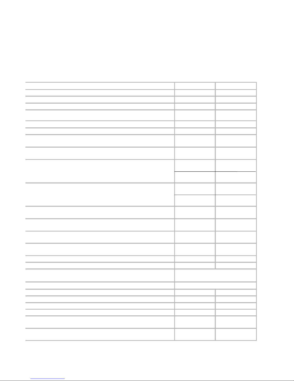
50Hz 60Hz
Nominal speed
1)
m3.h
-1
280 340
Pumping speed
1)
m3.h
-1
240 290
Ultimate partial pressure without gas ballast mbar
≤ 8.10
-2
≤ 8.10
-2
Ultimate total pressure with small gas ballast 4 Nm3/h mbar ≤ 0,5 ≤ 0,5
Ultimate total pressure with standard gas ballast 7.5 Nm3/h
also for EM gas ballast 10 Nm
3
/h
mbar
≤ 0,7 ≤ 0,7
Ultimate total pressure with big gas ballast 15 Nm3/h mbar
≤ 2,0 ≤ 2,0
Ultimate total pressure with two big gas ballasts 28 Nm3/h mbar
≤ 3,0 ≤ 3,0
Water vapour tolerance with small gas ballast 4 Nm3/h mbar
4
with turbine 220 mm5with turbine 220 mm
Water vapour capacity with small gas ballast 4 Nm
3
/h kg.h
-1
0,4
with turbine 220 mm
0,6
with turbine 220 mm
Water vapour tolerance with standard gas ballast 7.5 Nm
3
/h
also for EM gas ballast 10 Nm
3
/h
mbar
10
with turbine 220 mm
40
with turbine 150 mm
12
with turbine 220 mm
50
with turbine 150 mm
Water vapour capacity with standard gas ballast 7.5 Nm
3
/h
also for EM gas ballast 10 Nm
3
/h
kg.h
-1
1,3
with turbine 220 mm
6,0
with turbine 150 mm
1,8
with turbine 220 mm
8,0
with turbine 150 mm
Water vapour tolerance with big gas ballast 15 Nm
3
/h mbar
70
with turbine 150 mm70with turbine 150 mm
Water vapour capacity with big gas ballast 15 Nm
3
/h kg.h
-1
11
with turbine 150 mm14with turbine 150 mm
Water vapour tolerance with two big gas ballasts 28 Nm
3
/h mbar
95
with turbine 150 mm95with turbine 150 mm
Water vapour capacity with two big gas ballasts 28 Nm
3
/h kg.h
-1
15
with turbine 150 mm17with turbine 150 mm
Noise level
2)
dB(A) 70 74
Leak rate mbar.l.s
-1
≤ 1.10
-3
≤ 1.10
-3
Mains voltage (std) - for other voltages please contact Oerlikon Leybold
Vacuum
V
See
Ordering data
Motor power kW
See Ordering data
Type of protection IP55 IP55
Rated rotational speed min.-1 1450 1750
Weight (with oil filling) kg 200 200
Oil capacity (min./max.) l 8,5/11,5 8,5/11,5
Intake connection
G2 G2
NPT2
3)
nN
Exhaust connection G2 G2
NPT2
3)
1.3 Technical Data
1) according to DIN28400 and following numbers, with standard gas ballast
2) operated at ultimate pressure without gas ballast, free-field measurements at a distance of 1m
3) please contact Oerlikon Leybold Vacuum

7GA02330_002_06 - 01/2010 - © Oerlikon Leybold Vacuum
WATER COOLING
WATER QUALITY
TH(°F)
0°
CORROSION
(WATER TOO SOFT)
4° 8° 12° 20°
CARBONAT CONTENT
PPm
0
CORROSION
(AGRESSIVE WATER)
30 90 160 300
PH
CORROSION
(AGGRESSIVE WATER)
5 7.5
PRESSURE OF WATER NETWORK : 2 Bar MINI / 8 Bar MAXI
MINIMUM WATER SUPPLY : 600 L/H FOR WATER TEMPERATURE 15°C
VALVE REGULATION ON 2 FOR WARM AMBIANCES 40°C
MAX . WATER TEMPERATURE : 30°C
SERVICE AREA
INCRUSTING WATER
(DEPOSIT OF SCALE
SERVICE
AREA
INCRUSTING
WATER
VERY INCRUSTING
WATER
SERVICE AREA
INCRUSTING WATER
Description
Ordering data Ref. No. SV300 B
Pump with three-phase motor CEI w/o gas ballast
230 V/400 V, +/-10% , 50 Hz, 5,5kW
460 V, +/-10% , 60Hz, 6,3 kW
960 700
Pump with three-phase motor CEI and integrated gas ballast valve
230 V/400 V, +/-10% , 50 Hz, 5,5kW
460 V, +/-10% , 60Hz, 6,3 kW
960 702
Pump with three-phase motor NEMA and integrated gas ballast
208V +/-10% and 230/460 +/-10%, 60Hz, 10 hp
400V +/-10% 50Hz, 10 hp
960 707
Pump with three-phase motor JIS and integrated gas ballast valve
200V +10% -15%, 50/60Hz, 7,5 kW
960 712
Pump with wide range motor and integrated gas ballast valve
200V -15% ... 230V +10% / 380 ... 400 V +/-10%, 50Hz, 5,5 kW
200V -15% ... 230V +10% / 380 ... 400 V +/-10% & 460 +/-10%, 60Hz, 6,6 kW
960 717
Other gasballast variants available.
8 GA02330_002_06 - 01/2010 - © Oerlikon Leybold Vacuum
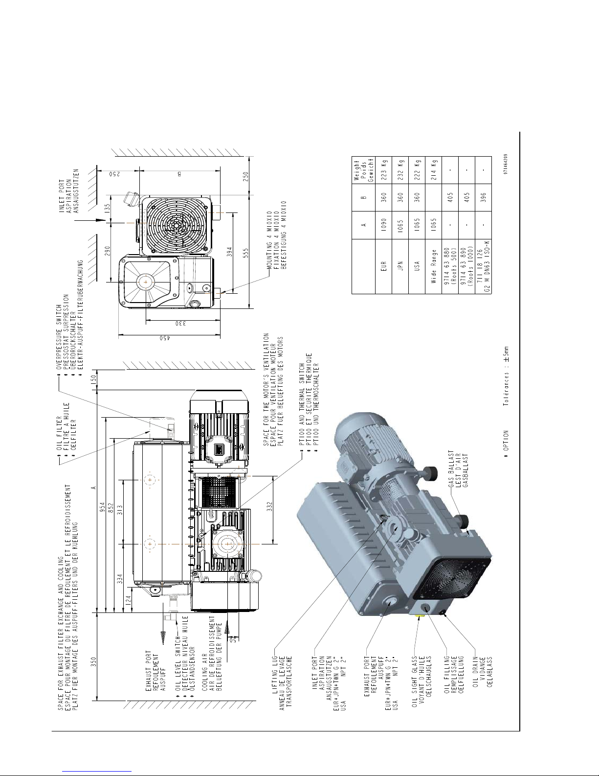
Description
Fig. 1a
384
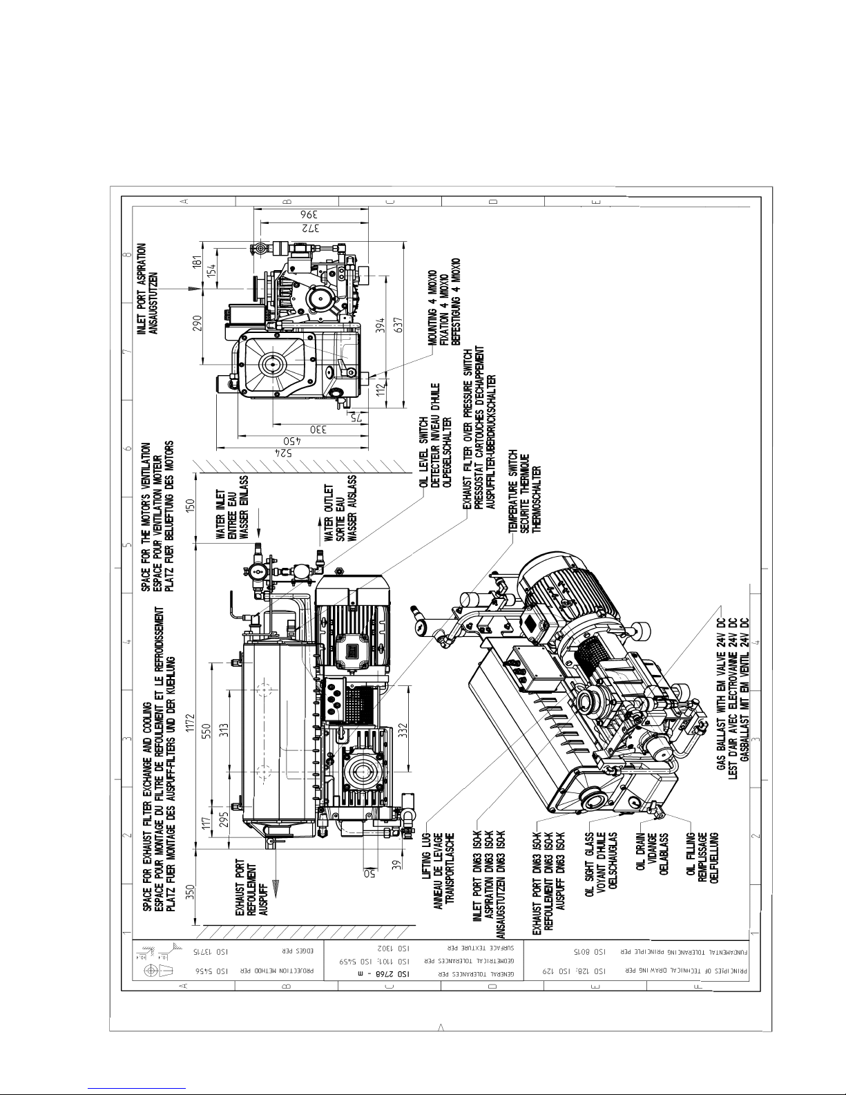
9GA02330_002_06 - 01/2010 - © Oerlikon Leybold Vacuum
Description
Fig. 1b
1 0 GA02330_002_06 - 01/2010 - © Oerlikon Leybold Vacuum
Description
without gas ballast with gas ballast
at 60Hz
mbar (millibar) torr
inches Hg
vacuum
1lb = 0.453 kg 1013 760 0
1 qt = 0.946 l 400 300 18.12
1 hp = 0.735 kW 133 100 25.98
1 inch = 25.4 mm 4 3 29.80
1 r.p.m. = 1 min - 1 0,75 29.89
0,1 0,75 29.92
1 atm (atmosphere) = 1013 mbar
1 Pa (pascal) = 0.01 mbar =10-2 mbar
1 bar = 1000 mbar
1 torr = 1.33 mbar
Different pressure units Different pumping speed units
m
3
.h-1 l.s
-1
cfm
m3. h-1 = m3/h 1 1 0.278 0.589
I.s-1 = I/s 3.60 1 2.12
cfm (cubic feet per minute) 1.699 0.472 1
Example : 1m
3.h-1
= 0.589 cfm
Note : the nominal pumping speed of a pump at 60Hz is
20% higher than at 50Hz
Conversion factors
at 50Hz
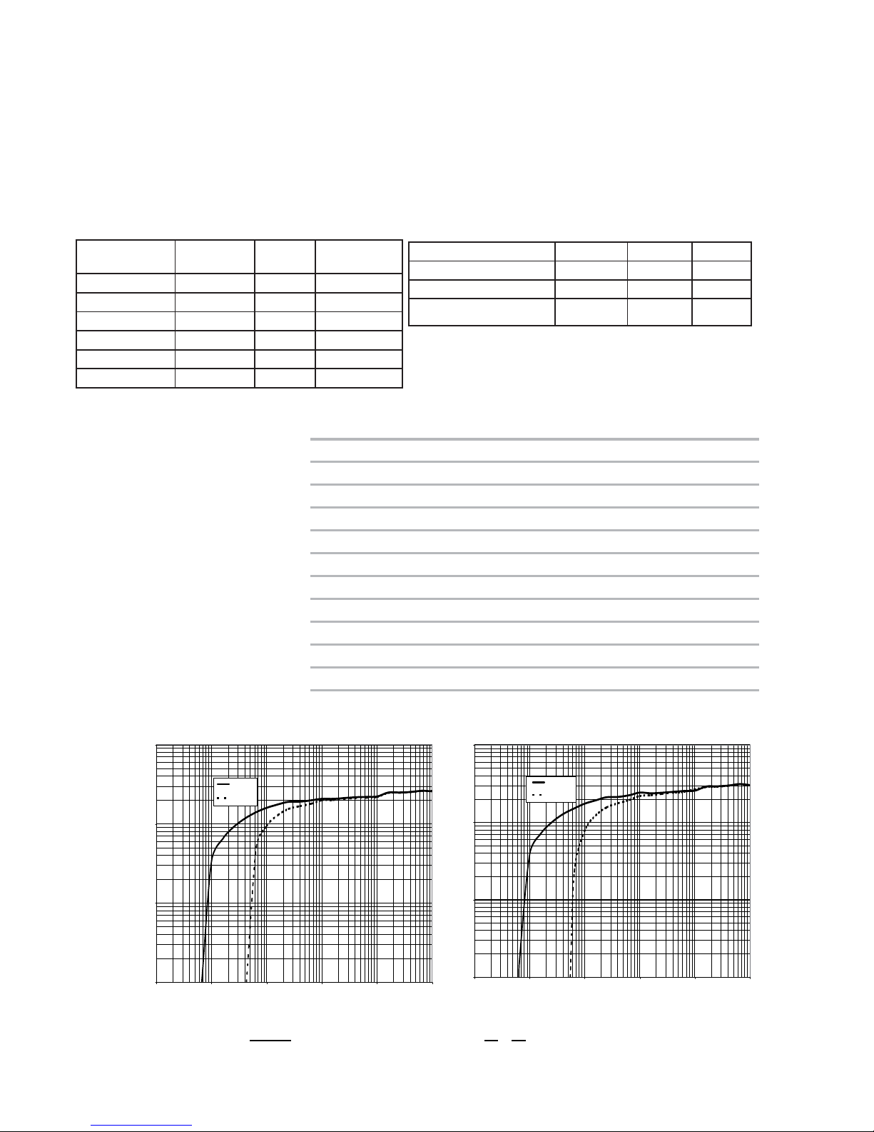
1
10
100
1000
0,01 0,1 1 10 100 1000
Pressure (mbar)
Pumping speed (m3/h)
60 Hz
GB 7,5 m3/h
1
10
100
1000
0,01 0,1 1 10 100 1000
Pressure (mbar)
Pumping speed (m3/h)
50 Hz
GB 7,5 m3/h
Fig. 2
60Hz
Nominal speed
1)
cfm 200
Pumping speed
1)
cfm 171
Ultimate partial pressure without gas ballast Torr
6.10
-2
Ultimate total pressure with gas ballast Torrr
0.5
Water vapour tolerance with standard gas ballast standard
1)
Tor r ≤ 30
Motor power hp 10.5
Rated rotational speed rpm 1750
Weight (with oil filling) lb 430
Oil capacity (min./max.) qt 9/12.2
Intake connection NPT (F) inches NPT2
Exhaust connection NPT (F) inches NPT2
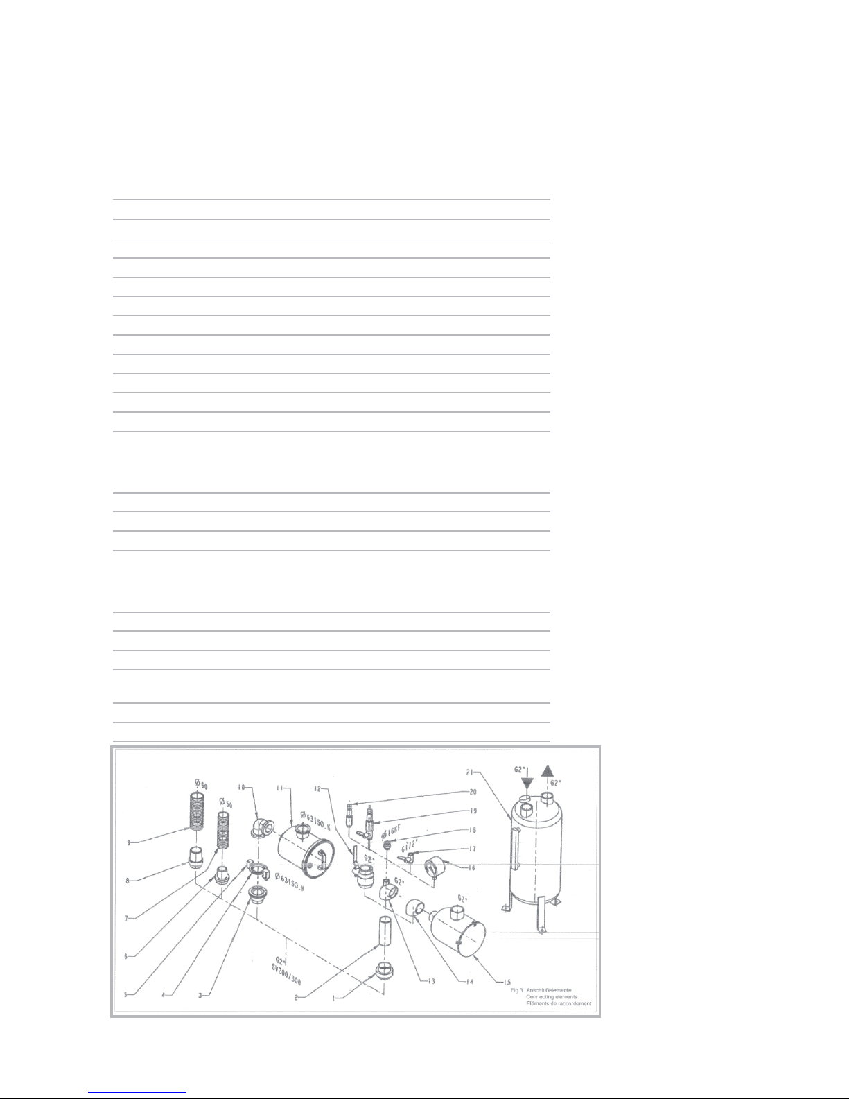
Item Description Size Cat. Nr.
1 Union coupling + seal G2 F/M 711 18 025
2 Nipple G2 M/M - 150 mm long 711 18 035
3 Threaded flange adapter G2 M - DN 63 ISO-K 711 18 126
4 Centering ring 63 ISO-K AL/NBR 268 07
5 Set of 4 clamps for M10 x 24 267 01
ISO-K flanges
6 Adapter for tubing G2 DN 50 711 18 015
7 PVC tubing 50 mm, 1 m long 711 18 325
8 Adapter for tubing G2 DN 60 711 18 016
9 PVC tubing 60 mm, 1 m long 711 18 326
10 Right-angle bend 90° 63 ISO K 887 25
11 Dust filter, paper
Dust filter, charcoal
Dust filter metal
Dust filter polyester
63 ISO K 951 68
711 27 125
711 27 126
711 27 127
12 Ball valve G2 F/F 711 30 107
13 Tee reducer bush G2-G2-G1/2 F/F/F 711 18 265
14 Elbow 90° G2 F/F 711 18 215
15 Dust filter, paper
Dust filter, charcoal
Dust filter, metal
Dust filter polyester
G2 M/F 951 65
711 27 122
711 27 123
711 27 124
16 Vacuum gauge G1/2 M 951 92
17 Ball valve G1/2 M/F 711 30 113
18 Threaded flange adapter G1/2 M - DN 16 KF 711 18 120
19 Regulation valve
with isolation valve
G1/2 M 951 87
20 Regulation valve G1/2 M 951 86
21 Condensate Trap G2 F -G2 F 951 44
Fig. 3
1 1GA02330_002_06 - 01/2010 - © Oerlikon Leybold Vacuum
1.4 Connection fittings
Description
 Loading...