

Oerlikon Leybold Vacuum PHOENIX L300i, PHOENIX L300i DRY, PHOENIX L300i MODUL Operating Manual
Operating Manual
GA10218_002_A7
Part numbers
250000V01
250001V01
250002V01
251000V01
251001V01
251100V01
251101V01

Contents
Important safety informations 5
1 Description 9
1.1 Design and Function .................................................................... 9
1.1.1 Vacuum Diagram PHOENIX L300i .............................................. 10
1.1.2 Vacuum Diagram PHOENIX L300i DRY ...................................... 11
1.1.3 Vacuum Diagram PHOENIX L300i MODUL ................................ 12
1.1.4 Vacuum Method ........................................................................ 13
1.1.5 Partial Flow Method ................................................................... 14
1.1.6 Sniffer Mode .............................................................................. 14
1.2 Supplied Equipment ................................................................... 14
1.3 Technical Data ........................................................................... 15
1.3.1 Technical Data PHOENIX L300i ................................................. 15
1.3.2 Technical Data PHOENIX L300i DRY ......................................... 17
1.3.3 Technical Data PHOENIX L300i MODUL .................................... 19
1.3.4 Dimensional Drawings ................................................................ 21
1.4 Ordering Information .................................................................. 24
1.5 Accessories ............................................................................... 24
1.6 Default Settings .......................................................................... 26
2 Installation 28
2.1 Placement ................................................................................. 28
2.2 Conforming Utilisation ................................................................ 28
2.3 Ambient Conditions ................................................................... 28
2.4 Electrical Connections ................................................................ 28
2.4.1 Mains Power .............................................................................. 28
2.4.2 Connection for the Controller Signal and Accessories ................ 30
2.4.3 Vacuum Connections ................................................................. 33
3 Operation 35
3.1 Media Compatibility/Purge Gas .................................................. 35
3.2 Start-Up ..................................................................................... 35
3.2.1 Display ....................................................................................... 35
3.2.2 The Display in Run-Up Mode ..................................................... 36
3.2.3 The Display in Standby Mode ..................................................... 36
3.2.4 Gas Ballast/Purge ..................................................................... 36
3.2.5 The Display in Measurement Mode ............................................ 36
3.2.6 Call for Calibration ...................................................................... 37
GA10218_002_A7 - 9/2015 - © Oerlikon Leybold Vacuum
2

3.2.7 Speaker Volume ........................................................................ 37
3.2.8 Status Line in the Display ........................................................... 37
3.2.9 Measurement Mode with Bargraph ............................................ 38
3.2.10 Measurement Mode with Trend Information ............................... 38
3.3 First Operation Check ................................................................ 38
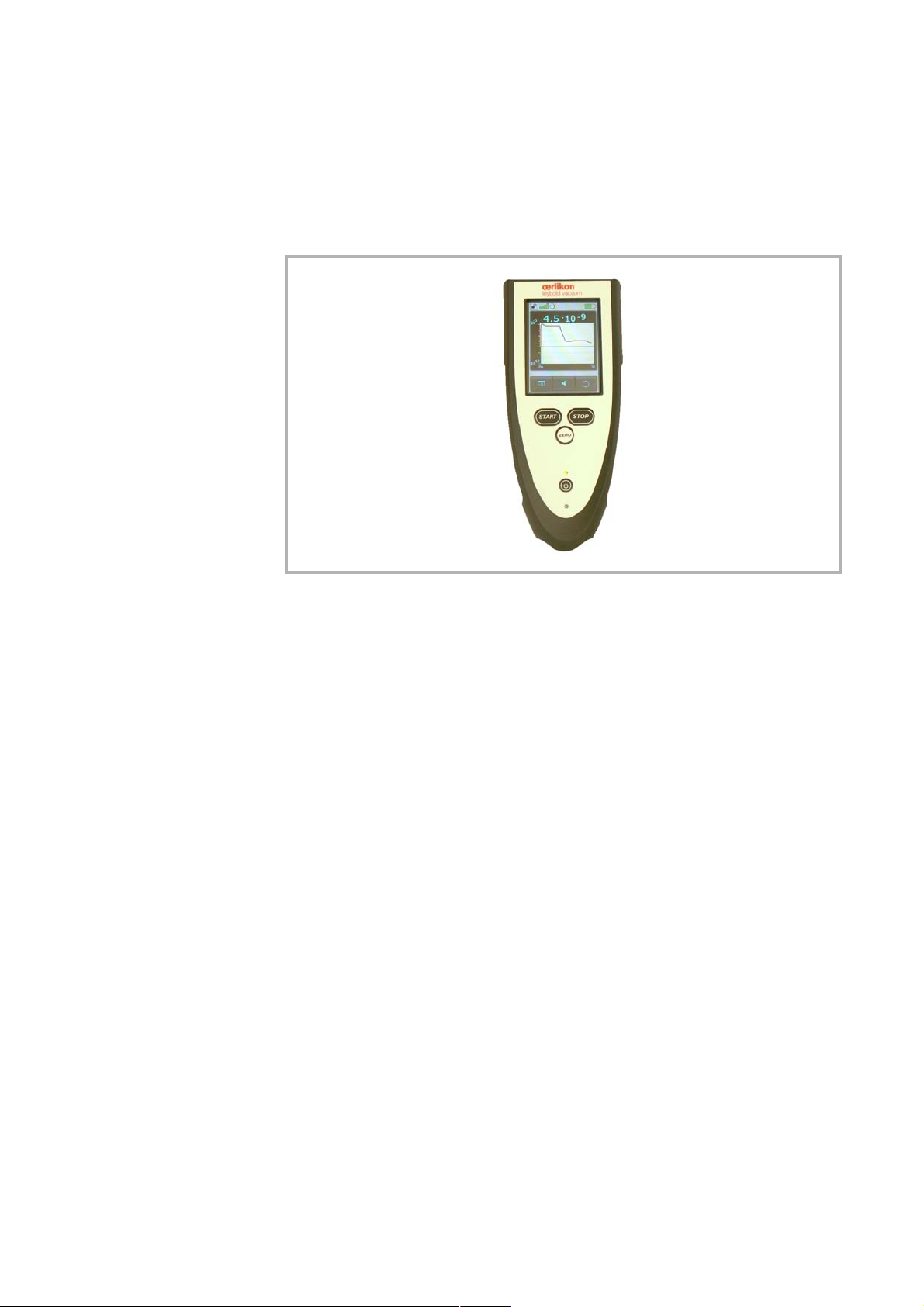
3.4 Control Panel ............................................................................. 40
3.5 Interfaces ................................................................................... 45
3.6 Operation .................................................................................. 52
3.6.1 Main Menu ................................................................................ 53
3.6.2 View .......................................................................................... 55
3.6.3 Scale Linear/Logarithmic ........................................................... 55
Contents
3.6.4 Display-Range Auto/Manual ...................................................... 56
3.6.5 Time Axis ................................................................................... 57
3.6.6 Contrast .................................................................................... 57
3.6.7 Background in standby .............................................................. 58
3.6.8 Lower Display Limit .................................................................... 58
3.7 Mode ......................................................................................... 59
3.8 Trigger & Alarms ........................................................................ 60
3.8.1 Trigger Level 1 ........................................................................... 60
3.8.2 Trigger Level 2 ........................................................................... 61
3.8.3 Trigger Level 3 ........................................................................... 61
3.8.4 Units .......................................................................................... 61
3.8.5 Volume ...................................................................................... 62
3.8.6 Alarm Delay ............................................................................... 62
3.8.7 Audio Alarm Type ...................................................................... 63
3.9 Calibration ................................................................................. 64
3.10 Settings ..................................................................................... 65
3.10.1 Vacuum Settings ....................................................................... 66
3.10.2 Filter & Background ................................................................... 74
3.10.3 Mass ......................................................................................... 76
3.10.4 Miscellaneous (Language, Calibration request, Service interval...) 76
3.10.5 Parameter Save/Load ................................................................ 79
3.10.6 Monitoring Functions ................................................................. 79
3.11 Information ................................................................................ 83
3.11.1 Service ...................................................................................... 83
GA10218_002_A7 - 9/2015 - © Oerlikon Leybold 3

Contents
3.12 Access Control .......................................................................... 84
3.12.1 Zero ........................................................................................... 84
3.12.2 Access to CAL Function ............................................................ 85
3.12.3 Change Menu-PIN ..................................................................... 85
3.13 Calibration ................................................................................. 85
3.13.1 Introduction ............................................................................... 85
3.13.2 The calibration Routines ............................................................. 86
3.13.3 Internal Calibration ..................................................................... 86
3.13.4 External Calibration .................................................................... 87
3.14 Switching Off/Shutting Down ..................................................... 89
4 Maintenance 90
4.1 Safety Information ...................................................................... 90
4.2 Maintenance Intervals ................................................................ 90
4.3 Oerlikon Leybold Vacuum Service .............................................. 90
4.4 Maintenance Work ..................................................................... 91
4.4.1 Opening of the PHOENIX L300i ................................................. 91
4.4.2 Exchanging the Filter Mats ......................................................... 92
4.4.3 Exchanging the Oil ..................................................................... 93
4.4.4 Cleaning .................................................................................... 93
4.4.5 Exchanging the Fuses ................................................................ 93
4.4.6 Exhaust Oil Filter ........................................................................ 95
4.4.7 Turbo Molecular Pump ............................................................... 95
4.5 Calibrated Leak TL7 ................................................................... 96
4.5.1 Technical Data ........................................................................... 96
4.5.2 Factory Inspection ..................................................................... 96
5 Troubleshooting 97
5.1 Hints for Troubleshooting ........................................................... 97
5.2 List of Errors & Warnings ............................................................ 97
6 Waste Disposal 105
GA10218_002_A7 - 9/2015 - © Oerlikon Leybold Vacuum
4
Important Safety Information
Safety Information
Indicates procedures that must be strictly observed to prevent hazards to persons.
Indicates procedures that must be strictly observed to prevent damage to, or
destruction of the product.
Emphasizes additional application information and other useful information provided within these Operating Instructions.
The Oerlikon Leybold Vacuum PHOENIX L300i leak detector has been
designed for safe and efficient operation when used properly and in accordance
with these Operating Instructions. It is the responsibility of the user to carefully
read and strictly observe all safety precautions described in this section and
throughout the Operating Instructions. The PHOENIX L300i must only be oper
ated in the proper condition and under the conditions described in the Operating Instructions. It must be operated and maintained by trained personnel only.
Consult local, state, and national agencies regarding specific requirements and
regulations. Address any further safety, operation and/or maintenance ques
tions to our nearest office.
Failure to observe the following precautions could result in serious
personal injury!
Electrical hazards
During all maintenance and connection work, make sure that the mains cable have
been reliable disconnected and do not carry a mains voltage.The leak detector
must only be used in with the hoods closed. The electrical connections must only
be provided by a trained electrician as specified, for example, by the regulations EN
50110-1.
-
-
Warning
Caution
Note
Warning
Avoid exposing any part of the human body to the vacuum. Only handle the leak
detector when the pump is vented.
After a mains power failure the leak detector can run up automatically once more.
Before changing oil or fuses, make sure that the mains cable have been disconnected.
The leak detector is not suited for operation in explosion hazard areas.
GA10218_002_A7 - 9/2015 - © Oerlikon Leybold 5

Safety Information
During operation the pump can become so hot that there is a danger of burns
(>70°C, 158°F).Provide protection against contact with the hot components.
Contaminated parts can be detrimental to health and environment. Before beginning to work, find out whether any parts are contaminated. Adhere to the relevant
regulations and take the necessary precautions when handling contaminated
parts.
Caution
Failure to observe the following precautions could result in damage to
the pump!
Unauthorized opening or modifications of the mechanical or electrical components
of the leak detector void the warranty.
The leak detector must only be opened by such persons who have been authorised by Oerlikon Leybold Vacuum to do so.
The leak detector can be damaged when using the wrong voltage. The voltage
must be in the range 230V (+/- 5%), 115V (+/- 5%) e.g. 100V (+/- 5%) depending
on the leak detector version. Make sure that the mains voltage rating on the PHOE
NIX L300i coincides with the locally available mains voltage.
When the PHOENIX L300i is running in closed rooms the exhaust has to be put out
of doors so that the oil vapor can not be breathed in.
Ensure a sufficient air cooling. The air inlet as well the air discharge openings must
never be obstructed. By using the optional iPad it is recommended to pull the fix
ture of the iPad into a raised position to optimize the cooling.
The PHOENIX L300i is designed for indoor use only.
Operate the PHOENIX L300i only in the permitted temperature range between
+10°C and +40°C.
-
-
Only Leybonol-LVO-310 (cat. no. L31001) must be used in the TIVAC D2,5E.
Pumping condensable gases and steams: When pumping test sample water
vapour that is inside the test object can attain to the forepump. With the water
vapor that is in the air - especially in humid areas or when using humid or wet test
samples - the acceptable compatibility of water vapor or capacity of water vapor
respectively can be exceeded.
The steam in the oil of the pump condenses when the water vapor rises over the
acceptable value. So the attribute of the oil changes and danger of corrosion
occurs for the pump.
While using the leak detector with condensable gases and steams the oil of the
forepump has to be controlled regularly. So you can recognize a condensation of
water vapor in the pump. Usually the oil is light and lucent. When water vapor is
GA10218_002_A7 - 9/2015 - © Oerlikon Leybold Vacuum
6
Safety Information
inside it gets blear and milky at operating state temperature.
When turning the pump off water vapor condensates and raises the part of water in
the oil.
The leak detector must not directly be switched off after the process, in which condensable gases or steams are pumped, is finished. It must be running (at least 20
minutes) with opened gas ballast valve until the oil of the pump is freed from
detached steam.
When not taking care of this instruction there can be a corrosion within the pump,
which will not be covered by our warranty.
The height of the oil of the pump has to be controlled regularly.
The normal intervals of changing the oil from the producer have to be taken care of.
See instructions of the rotary vane pump.
The references to diagrams, e.g. (1/2) consist of the Fig. no. and the item No. in
that order.
We reserve the right to alter the design or any data given in these Operating
Instructions. The illustrations are not binding.
Retain the Operating instructions for further use.
Figures
Symbols of vacuum technology
Given in the following are some important symbols which are used in this Operating
Instructions.
Vacuum pump in general
Turbo molecular pump
Measuring instrument
Valve
Definition of Terms
The range of the preamplifier and the vacuum ranges are selected automatically.
The auto ranging feature of the PHOENIX L300i covers the entire range or leak
rates depending on the selected operating mode. Not only the leak rate signal, but
also the pressure in the test sample (inlet pressure P1) and the fore vacuum pres
sure (P2) are used for control purposes. Range switching between the main ranges
is performed via valves. Fine range switching within the main ranges is imple
mented by switching over the gain factor of the preamplifier.
Auto ranging
-
-
GA10218_002_A7 - 9/2015 - © Oerlikon Leybold 7

Safety Information
Mass alignment
Mass alignment
This function automatically aligns the mass spectrometer so that a maximum leak
rate is displayed. The control processor changes the voltage which accelerates the
ions in the selected mass range until a maximum ion current is detected by the ion
Auto Zero
GROSS
detector. During each calibration the mass alignment is run automatically.
Determination and automatic adaptation of the internal background.
Through this function, the internal zero level of the instrument is determined which
is then subtracted from the current leak rate signal. This function is run during the
calibration process or when operating the start push button, provided the PHOE
NIX L300i has been running previously for at least 20 seconds in the standby or
vent mode.
GROSS is a measurement mode which allows high inlet pressure (15 to 0,2 mbar).
The smallest detectable leak rate is 1
-
· 10-7 mbar l / s.
FINE
PRECISION
Fore-Vacuum Pressure
Internal helium background
Minimum detectable leak
rate
Menu
Measurement mode
Default
FINE is a measurement mode with inlet pressure < 0.2 mbar. The minimum detectable leak rate is 5 · 10
Precision is a measurement mode for the PHOENIX L300i DRY only from an inlet
pressure < 0,01 mbar. In this mode the PHOENIX L300i DRY has the highest sen
sitivity, the minimum detectable leak rate is 3 · 10
Pressure in the fore vacuum between turbo pump and rotary vane pump.
The existing helium partial pressure in the measurement system. The level of the
internal helium background is measured in the standby mode and subtracted from
the measured signal.
The smallest leak rate the PHOENIX L300i is able to detect ( 5·10
vacuum mode.
The menu allows the user to program the PHOENIX L300i according to his requirements. The menu has a tree architecture.
The PHOENIX L300i measures the leak rate of the test sample.
Status of the PHOENIX L300i when supplied by the factory.
-12
mbar l / s.
-11
mbar l / s.
-12
mbar l / s) in
-
GA10218_002_A7 - 9/2015 - © Oerlikon Leybold Vacuum
8
1 Description
1
2
The PHOENIX L300i is a leak detector for helium or hydrogen. This instrument may
be used to detect the location and the size of leaks on objects under test in two dif
ferent ways:
When the test sample has been evacuated first and is sprayed with helium on the
outside. It is required that a vacuum connection is provided between the PHOENIX
L300i and the test sample (vacuum mode).
or
when a helium overpressure is provided in the test sample and the test sample is
searched from the outside with a sniffer probe which is attached to the inlet port
(sniffer mode).
Description
-
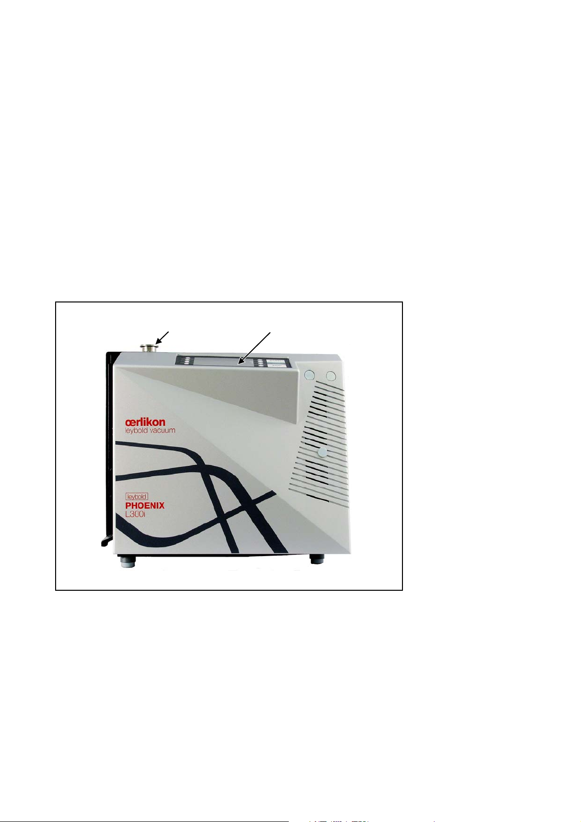
Fig. 1 View of the PHOENIX L300i
1 inlet flange 2 control panel
1.1 Design and Function
The PHOENIX L300i basically is a helium leak detector for vacuum applications, i.e.
the part under test is evacuated while the test is performed. The vacuum is
achieved with a pumping system that is part of the PHOENIX L300i. In addition the
vacuum can be generated by pumps which are set up in parallel to the PHOENIX
L300i.
The PHOENIX L300i MODUL needs a fore vacuum pump, dry or wet version, to be
connected because this unit has no internal roughing pump. The connection
(DN25 KF) is on the side or under the bottom of the PHOENIX L300i MODUL (
7).
Fig.
GA10218_002_A7 - 9/2015 - © Oerlikon Leybold 9

Description
1
2
7
4
6
5
3
Another operating mode of the PHOENIX L300i is the Sniffer mode which can only
be used when a sniffer line (See Chapter
1.1.6) is hooked up.
1.1.1 Vacuum Diagram PHOENIX L300i
The vacuum diagram below shows the major components inside the PHOENIX
L300i.
Fig. 2 Vacuum diagram PHOENIX L300i
Pos. Description
1 MS: Mass Spectrometer, Helium sensor (180° magnetic field mass
spectrometer)
2 Turbo molecular pump (TMP, provides high vacuum conditions in
the MS)
3 Pirani gauge P2 (fore vacuum pressure)
4 Fore pressure pump (provides the fore vacuum pressure for the
TMP and pumps down the parts under test)
5 Inlet Port
6 Pirani gauge P1 (inlet pressure)
V1 … V7: Electromagnetic Valves to control the gas flows
The mass spectrometer (MS) is mainly composed of the ion source with cathode,
the magnetic separator and the ion collector.
Gas molecules getting into the mass spectrometer are ionized by the ion source.
These positively charged particles are accelerated into the magnetic field following
a circular path, the radius of which depends on the mass-to-charge ratio of the
ions. When mass 4 is selected (Default setting) only helium ions can pass this filter
and reach the ion collector where the stream of the ions is measured as an electri
-
GA10218_002_A7 - 9/2015 - © Oerlikon Leybold Vacuum
10
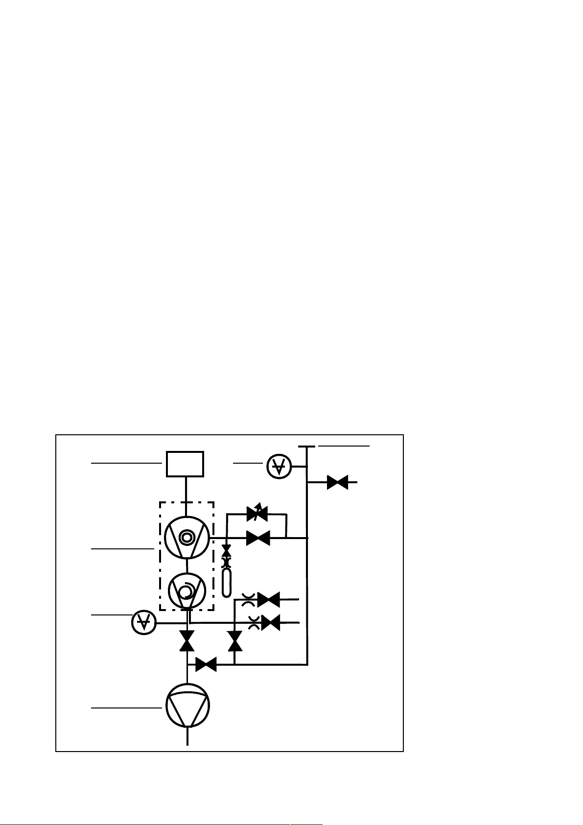
cal current. When selected another mass than 4, only the corresponding ions can
MS
P
1
V
1
V
2a
V
3
V
2b
P
2
V
V
4 a
4 b
V
6
V
5
V
7
1
2
3
6
5
4
Diaphragm pump
pass the filter.
For operation the mass spectrometer requires a vacuum level in the range of 1·10
4
mbar and lower. This pressure is provided by the turbo molecular pump which in
turn is backed up by a fore vacuum pump.
Besides maintaining the pressure in the mass spectrometer the pump system is
used to evacuate the test parts. It is made sure that the pressure in the mass spec
trometer is low enough under all circumstances. The valves V1, V2a, V2b, V4a
control the gas flows when measuring. Valves V3 and V5 are used to vent the sys
tem and the Turbo pump, valve V6 controls the gas ballast function of the fore vacuum pump. Valve V7 opens and closes the internal test leak during calibration.
With the pressure in the test part being lower than ambient pressure sprayed
helium (or Hydrogen as forming gas) can penetrate into the part in case of a leak
age. As soon as the pressure conditions allow it one of the valves to the TMP
opens. Now Helium can penetrate into the mass spectrometer contrary to the
pumping direction of the TMP.
Description
-
1.1.2 Vacuum Diagram PHOENIX L300i DRY
The PHOENIX L300i DRY has a diaphragm pump as fore vacuum pump, making it
suitable for applications where oil sealed systems can not be used. Furthermore
the PHOENIX L300i DRY contains one more valve, the valve 4b. This valve opens
step by step to regulate the inlet pressure into the turbo pump.
Fig. 3 Vacuum diagram PHOENIX L300i DRY
GA10218_002_A7 - 9/2015 - © Oerlikon Leybold 11

Description
MS
P
1
V
1
V
2a
V
3
V
2b
V
6
P
2
V
4a
external pump
V
5
V
7
1
2
4
5
3
6
Pos. Description
1 MS: Mass Spectrometer, Helium sensor (180° magnetic field mass
spectrometer)
2 Turbo molecular pump (TMP, provides high vacuum conditions in
the MS)
3 Pirani gauge P2 (fore vacuum pressure)
4 Diaphragm pump (provides the fore vacuum pressure for the TMP
and pumps down the parts under test)
5 Inlet Port
6 Pirani gauge P1 (inlet pressure)
V1 … V7: Electromagnetic Valves to control the gas flows
1.1.3 Vacuum Diagram PHOENIX L300i MODUL
The PHOENIX L300i MODUL has no roughing pump integrated as the other models. Therefore it can be used with an external pump only. This pump can be oil
sealed or a dry version with a roughing capacity between 2.5 and 65 m
3
/h. This
pump has to be connected to the DN25 KF at the side or under the bottom of the
PHOENIX L300i MODUL.
Fig. 4 Vacuum diagram PHOENIX L300i MODUL
GA10218_002_A7 - 9/2015 - © Oerlikon Leybold Vacuum
12

Pos. Description
1 MS: Mass Spectrometer, Helium sensor (180° magnetic field mass
spectrometer)
2 Turbo molecular pump (TMP, provides high vacuum conditions in
the MS)
3 Pirani gauge P2 (fore vacuum pressure)
4 Fore pressure pump (provides the fore vacuum pressure for the
TMP and pumps down the parts under test)
5 Inlet Port
6 Pirani gauge P1 (inlet pressure)
V1 … V7: Electromagnetic Valves to control the gas flows
1.1.4 Vacuum Method
For the purpose of leak detection on a test sample (vacuum method), the sample
has to be evacuated so that Helium or Hydrogen which is sprayed on to the out
side, can enter through any leaks due to the pressure differential for detection by
the PHOENIX L300i.
Description
-
The test sample is evacuated - START button (Fig 16./10) - by the backing pump
or the external pump. In the case of larger test samples an additional external par
tial flow pump with a corresponding linking valve may be connected in parallel as
required.
Inlet valve V1 is opened so that the evacuation can take place. At the same time all
other valves are closed in order to prevent an unacceptable pressure increase in
the mass spectrometer.
In this context (valve V2a closed) the turbo molecular pump is operated without
being supported by the rotary vane pump. Since generally no gas is pumped out of
the mass spectrometer, p
The condition for the evacuation process described here is maintained until the
inlet pressure p1 has dropped <15
additionally. Possibly present Helium or Hydrogen may now flow upstream against
the pumping direction of the turbo molecular pump into the mass spectrometer
where it is detected. This measurement mode is called GROSS. In this mode, leak
rates down to 10
Since the rotary vane vacuum pump continues to evacuate the test sample via
valves V2a, V2b and V1 the inlet pressure p
sure drops below p1 < 0.2 mbar, the PHOENIX L300i will switch to the FINE mode,
i.e. valve V1and V2b closes and valve V4a opens so that the gas flow enters the
turbo molecular pump at the side. This offer two advantages:
-8
mbar l/s can be detected.
remains constant or increases only slowly.
2
mbar. Now the valves V2a and V2b are opened
will continue to drop. When the pres-
1
-
a) A part of the high pumping speed of the turbo molecular pump
remains available for further evacuation of the test sample. The
response time is inversely proportional to pumping speed.).
b) The advantages offered by the counter flow principle can still be uti-
lized
In the FINE mode the full sensitivity of the PHOENIX L300i is reached.
Because of the higher base pressure of the diaphragm pump the switching from
GROSS to FINE mode of the PHOENIX L300i DRY is done by the valve V4b. When
the pressure drops below 3,5
mbar the valves V1 and V2b will be close and V4b
GA10218_002_A7 - 9/2015 - © Oerlikon Leybold 13

Description
opens step by step. When valve V4b is open completely, pressure < 0,1 mbar, V4a
will open also to get the maximum pumping speed. In PRECISION mode the
PHOENIX L300i DRY opens the valve V4b only, with the disadvantage of low
pumping speed but with the highest sensitivity.
When the leak detection process is stopped – STOP-button – all valves except
valve V2a are closed.
Valve V3 is opened during venting of the inlet or test sample.
1.1.5 Partial Flow Method
In the partial flow mode the test sample is additionally evacuated by an auxiliary
pump. Using the optional partial flow pump set offers to the user the following
advantages (PHOENIX L300i
- faster response time
- entry into the measure mode already at an inlet pressure of 1000 mbar
- faster venting of large test objects
and PHOENIX L300i MODUL:
Alternatively to a partial flow pump set an external auxiliary pump may also be connected via a tee, this option is possible for the PHOENIX L300i dry and PHOENIX
L300i MODUL also. However, in such a case the PHOENIX L300i will not be able to
make measurements already at an inlet pressure of 1000
1.1.6 Sniffer Mode
The PHOENIX L300i may simply be converted into a sniffer leak detector via the
rugged sniffer line (Cat. No. 252003)
For this the KF flange of the sniffer line is connected to the inlet flange (Fig. 1/1) and
the sniffer mode is selected through menu mode. After pressing START, the inlet
valve V1 (
PHOENIX L300i is operated in the FINE mode. If the fore vacuum pressure P2
increases over 0,2 mbar respectively 0,1 mbar a warning sign and audio alarm
comes up in the display
In the measurement mode the helium present in the ambient air is now indicated as
the leak rate (about 2
the ZERO-button. In sniffer mode the smallest detectable leak rate is < 1· 10
mbarl/s.
1.2 Supplied Equipment
The PHOENIX L300i will be shipped in a special cardboard packed separately in a
plastic foil as protection against dust.
Supplied equipment includes:
Fig. 2) opens. The sniffer lines have been designed in such a way that the
· 10-6 mbar l/s). Smaller leaks may be detected by pressing
mbar.
-7
Leak Detector PHOENIX L300i
Set of fuses
Power cord
Folder with documents (Operating instructions, Spare part list)
2 L-type screwed connections (hose connections)
1 hose nozzle
Blank flange DN 25 KF
Clamping ring DN 25 KF
Centering ring DN 25 KF
GA10218_002_A7 - 9/2015 - © Oerlikon Leybold Vacuum
14

1.3 Technical Data
1.3.1 Technical Data PHOENIX L300i
Physical data
Max. inlet pressure 15 mbar
Minimum detectable Helium leak rates
- in vacuum mode
- in sniffer mode
Minimum detectable Hydrogen leak rates
- in vacuum mode
- in sniffer mode
Maximum Helium leak rate which can be displayed 0.1 mbar l / s
Measurement range 12 decades
Time constant of the leak rate signal (blanked off,
63% of the final value)
Pumping speed (Helium) at the inlet
- GROSS mode 0.4 l/s
- FINE mode > 2.5 l/s
Detectable masses 2, 3 and 4
Mass spectrometer 180° magnetic sector
Ion source 2 filaments;
Inlet port DN 25 KF
Run-up time (after starting) < 2 min
To get down to the minimum detected leak rate range some conditions must be
fulfilled:
-12
<5·10
<1·10-7 mbar l / s
<1·10-8 mbar l / s
<1·10-7 mbar l / s
<1 s
field
Iridium/Yttrium-oxide
mbar l / s
Description
Physical data
PHOENIX L300i has to run at least 20 minutes
Ambient conditions must be stable (temperature, no vibration/accelerations.)
The part under test has been evacuated long enough without using the zero function (background is no longer decreasing)
ZERO must be active
GA10218_002_A7 - 9/2015 - © Oerlikon Leybold 15

Description
Electrical data
Other data
Electrical data
Power supply Cat.-No.250000V01
Cat.-No.251000V01
Cat.-No.251100V01
Power consumption 420 VA
Type of protection IP40
Other data
Valves solenoid
Dimensions (L × W × H) in mm 495 x 456 x 314
Weight in kg 40.0
Noise level dB (A) < 54
max. Audio alarm dB (A) 90
Contamination level (to IEC 60664-1) 2
Overvoltage category (to IEC 60664-1) II
230 V, +/- 5%, 50/60 Hz
115 V, +/- 5%, 60 Hz
100 V, +/- 5%, 50/60 Hz
Ambient conditions
Ambient conditions
For use within buildings
Permissible ambient temperature (during operation) +10 °C … +40 °C
Permissible storage temperature -10 °C … +60 °C
Maximum relative humidity 80% (up to 31°C) lin-
ear decreasing to
50% at 40°C
Max. permissible height above sea level
(during operation)
2000 m
GA10218_002_A7 - 9/2015 - © Oerlikon Leybold Vacuum
16

Description
1.3.2 Technical Data PHOENIX L300i DRY
Physical data
Max. inlet pressure 15 mbar
Minimum detectable Helium leak rates
- in vacuum mode
- in sniffer mode
Minimum detectable Hydrogen leak rates
- in vacuum mode
- in sniffer mode
Maximum Helium leak rate which can be displayed 0.1 mbar l / s
Measurement range 11 decades
Time constant of the leak rate signal (blanked off,
63% of the final value)
Pumping speed (Helium) at the inlet
GROSS mode 0.02 l / s
PRECISION mode 0,4 l / s
FINE mode > 2.5 l / s
Detectable masses 2, 3 and 4
Mass spectrometer 180° magnetic sector
Ion source 2 filaments;
Inlet port DN 25 KF
Run-up time (after starting) < 2 min
-11
< 3·10
< 1·10-7 mbar l / s
< 1·10-8 mbar l / s
< 1·10-7 mbar l / s
<1 s
field
Iridium/Yttrium-oxide
mbar l / s
Physical data
To get down to the minimum detected leak rate range some conditions must be
fulfilled:
PHOENIX L300i has to run at least 20 minutes
Ambient conditions must be stable (temperature, no vibration/accelerations.)
The part under test has been evacuated long enough without using the zero function (background is no longer decreasing)
ZERO must be active
GA10218_002_A7 - 9/2015 - © Oerlikon Leybold 17

Description
Electrical data
Other data
Electrical data
Power supply Cat.-No.250001V01
Cat.-No.251001V01
Cat.-No.251101V01
Power consumption 350 VA
Type of protection IP40
Other data
Valves solenoid
Dimensions (L × W × H) in mm 495 x 456 x 314
Weight in kg 35.5
Noise level dB (A) < 54
max. Audio alarm dB (A) 90
Contamination level (to IEC 60664-1) 2
Overvoltage category (to IEC 60664-1) II
230 V, 50 Hz
115 V, 60 Hz
100 V, 50/60 Hz
Ambient conditions
Ambient conditions
For use within buildings
Permissible ambient temperature (during operation) +10 °C … +40 °C
Permissible storage temperature -10 °C … +60 °C
Maximum relative humidity 80% (up to 31°C) lin-
ear decreasing to
50% at 40°C
Maximum permissible height above sea level
(during operation)
2000 m
GA10218_002_A7 - 9/2015 - © Oerlikon Leybold Vacuum
18

Description
1.3.3 Technical Data PHOENIX L300i MODUL
Physical data
Max. inlet pressure 15 mbar
Minimum detectable Helium leak rates
in vacuum mode
- with Scroll pump
- with oil sealed pump
in sniffer mode
Minimum detectable Hydrogen leak rates
- in vacuum mode
- in sniffer mode
Maximum Helium leak rate which can be displayed 0.1 mbar l / s
Measurement range 12 decades
Time constant of the leak rate signal (blanked off,
63% of the final value)
Pumping speed (Helium) at the inlet
GROSS mode 1,0 l / s
FINE mode > 2.5 l / s
Detectable masses 2, 3 and 4
Mass spectrometer 180° magnetic sector
Ion source 2 filaments;
Inlet port DN 25 KF
Run-up time (after starting) < 2 min
-12
< 8·10
< 5·10
<1·10-7 mbar l / s
< 1·10-8 mbar l / s
< 1·10-7 mbar l / s
< 1 s
field
Iridium/Yttrium-oxide
mbar l / s
-12
mbar l / s
Physical data
To get down to the minimum detected leak rate range some conditions must be
fulfilled:
PHOENIX L300i has to run at least 20 minutes
Ambient conditions must be stable (temperature, no vibration/accelerations.)
The part under test has been evacuated long enough without using the zero function (background is no longer decreasing)
ZERO must be active
GA10218_002_A7 - 9/2015 - © Oerlikon Leybold 19

Description
Electrical data
Other data
Ambient conditions
Electrical data
Power supply Cat. No. 250002V01 100 - 240 V
50/60 Hz
Power consumption 200 VA
Type of protection IP40
Power cords (EU, USA, UK) 2.5 m
Other data
Valves solenoid
Dimensions (L × W × H) in mm 495 x 456 x 314
Weight in kg 35.5
Noise level dB (A) < 54
max. Audio alarm dB (A) 90
Contamination level (to IEC 60664-1) 2
Overvoltage category (to IEC 60664-1) II
Ambient conditions
For use within buildings
Permissible ambient temperature (during operation) +10 °C … +40 °C
Permissible storage temperature -10 °C … +60 °C
Maximum relative humidity 80% (up to 31°C) lin-
ear decreasing to
50% at 40°C
Maximum permissible height above sea level
(during operation)
2000 m
GA10218_002_A7 - 9/2015 - © Oerlikon Leybold Vacuum
20
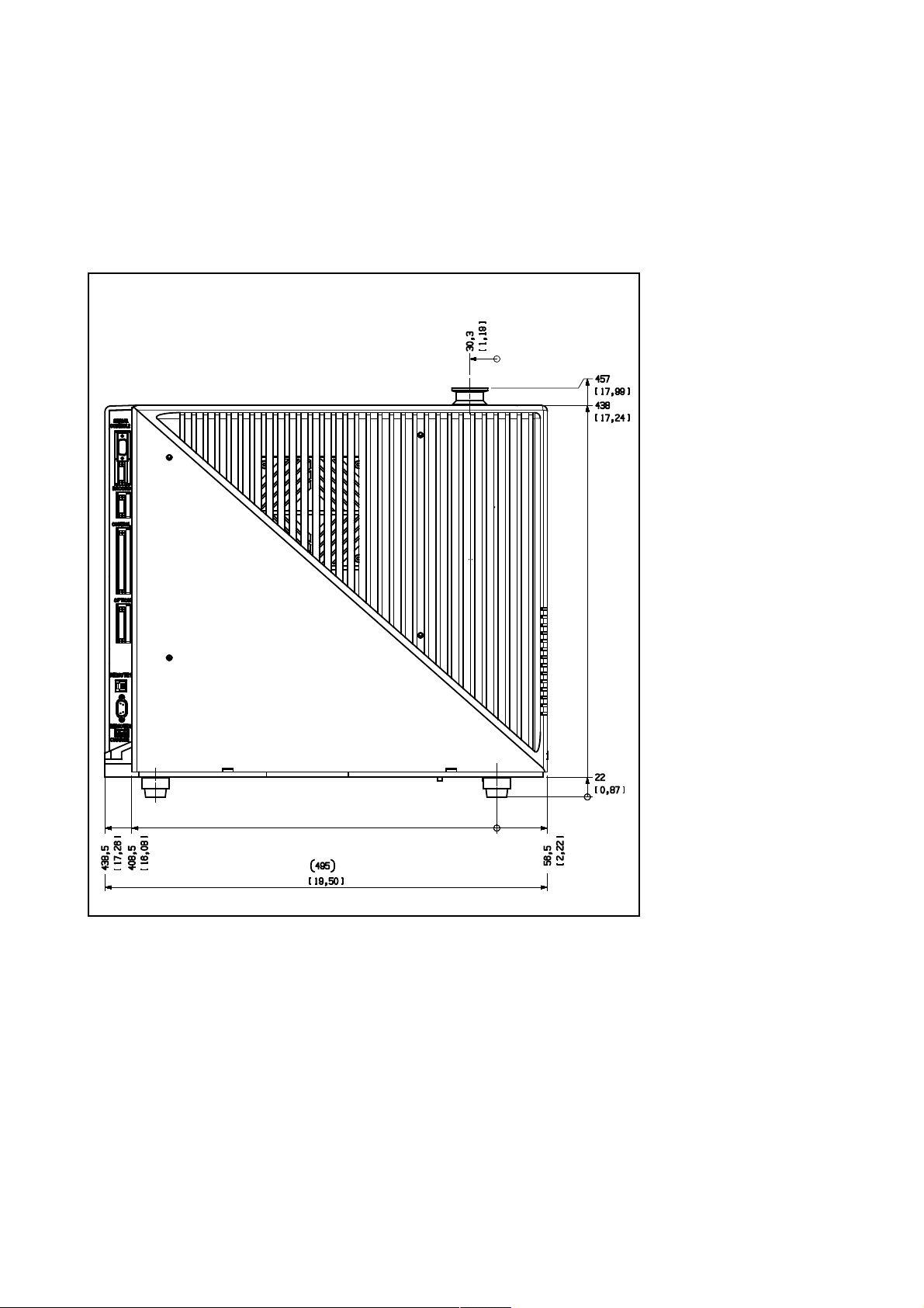
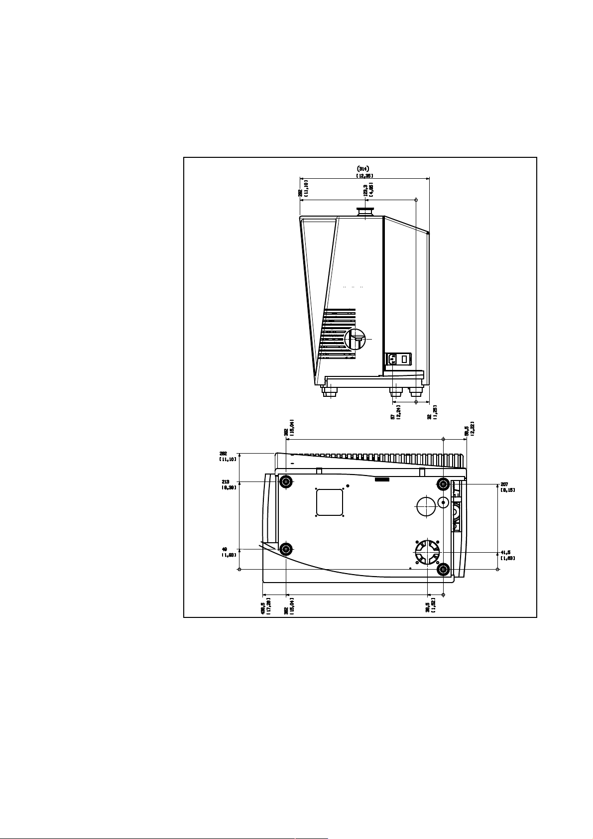
1.3.4 Dimensional Drawings
Abmaße PHOENIX L300i Familie in mm und inch. (in Klammern)
Dimensions PHOENIX L300i family in mm and inches (in brackets).
Description
Fig. 5 Dimensions PHOENIX L300i
GA10218_002_A7 - 9/2015 - © Oerlikon Leybold 21
Description
Abmessungen PHOENIX L300i Familie
in mm und inch. (in Klammern)
Dimensions family inPHOENIX L300i
mm and inches (in brackets)
GA10218_002_A7 - 9/2015 - © Oerlikon Leybold Vacuum
22
Fig. 6 Dimensions PHOENIX L300i side view
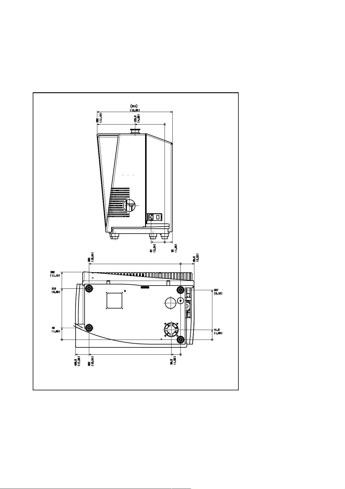
Description
Abmessungen
PHOENIX L300i in mm
und inch (in Klammern).
Dimensions PHOENIX L300i
in mm and inches (in brackets).
Fig. 7 Dimensions PHOENIX L300i MODUL
GA10218_002_A7 - 9/2015 - © Oerlikon Leybold 23

Description
1.4 Ordering Information
PHOENIX L300i EU-Version 250000V01
PHOENIX L300i DRY EU-Version 250001V01
PHOENIX L300i MODUL 250002V01
PHOENIX L300i US-Version 251000V01
PHOENIX L300i DRY US-Version
PHOENIX L300i JP-Version 251100V01
PHOENIX L300i JP-Version 251101V01
1.5 Accessories
The following parts can be ordered additionally:
251001V01
Sniffer line SL300 252003
Leak Ware (Software for data acquisition) 14090
Helium Sniffer QUICK-TEST Qt 100 15594
Remote control set RC310C consisting of:
- Remote control
- cable 4 m
- mounting parts
Extension cable for remote control,10m
Remote control set RC310WL wireless
consisting of:
- Remote control
- Radio transmitter
- mounting parts
Radio transmitter for remote control 252015V01
Spray gun with hose 16555
Set of connection plugs 20099024
Partial flow system (PHOENIX L300i and PHOENIX
L300i MODUL)
Adapter USB/RS232 800110V0103
iPad inclusive Software-APP & Protection Case
(IP67) PHOENIX L300i
WLAN Module iPad 252006V01
iPad holder PHOENIX L300i 252007V01
BARCODE Scanner iPad Phoenix L300i 252008V01
iPad table stand 252009V01
iPad theft protection 252010V01
iPad communication cable 252011V01
252013V01
14022
252014V01
14020
252005V01
GA10218_002_A7 - 9/2015 - © Oerlikon Leybold Vacuum
24

Description
Sniffer line SL300
By use of the sniffer line the PHOENIX L300i can easily be converted to a sniffer
leak detector. The length of the sniffer line is 4m (i.e. 12 feet).
Installation:
The sniffer line is to be adapted to the KF 25 of the PHOENIX L300i (Fig. 1/1) with
the small flange. The electrical plug of the sniffer line is to be connected to the input
„Options“ (
Function:
The green LED is on when
- the PHOENIX L300i is ready for use and
- the selected trigger level is not exceeded
The red LED is on when
- the PHOENIX L300i is not ready for use or
- the selected trigger level is exceeded.
The push button in the grip is for the zero function. When pushing the button the
helium background will be suppressed. For cancelling the zero function push the
button once more.
Options for the sniffer line:
Fig. 9/9) of the PHOENIX L300i.
Sniffer line SL300
Sniffer tip rigid 120 mm 12213
Sniffer tip rigid 385 mm 12215
Sniffer tip flexible 120 mm 12214
Sniffer tip flexible 385 mm 12216
Capillary filter metal (for rough conditions) 12217
Spare parts for the sniffer line
Capillary filter plastic (5 pcs) 20003501
Sinter filter with seal (5 pcs) 20003500
Felt disc for capillary filter (50 pcs) 200001116
GA10218_002_A7 - 9/2015 - © Oerlikon Leybold 25
Description
Remote control
Partial flow system
Remote Control RC310WL Wireless and RC310C Wired
Fig. 8 Remote Control RC310WL wireless
For further information of the remote control RC310WL and RC310C see instruction manual with the document number 300306406_002_A1.
Partial Flow System (PHOENIX L300i and PHOENIX L300i
In the partial flow mode the test sample is additionally evacuated by an auxiliary
pump. Using the optional partial flow pump set offers to the user the following
advantages:
- faster response time
- entry into the measurement mode already at an inlet pressure of 1000 mbar
- faster venting of large test objects
The partial flow system consists of the components partial flow valve block, right
angle valve DN 25 KF, control cable and vacuum hose with flange connections.
The partial flow valve block with the right angle valve has to be connected to the
inlet flange of the PHOENIX L300i. Connect the control cable to the Option port
and the vacuum hose to the auxiliary pump. The PHOENIX L300i has to be config
urated as described in chapter.
For further detailed information please refer to operating instructions GA 10.277
partial flow system.
1.6 Default Settings
The following parameters are set like shown when in the menu of the PHOENIX
L300i under Settings > Parameters, Load / Save is chosen.
Scale linear
Display range: 4 decades
Time axis: 32 seconds
LCD inverted off
Background in standby mode: off
-
GA10218_002_A7 - 9/2015 - © Oerlikon Leybold Vacuum
26

Calibration request: off
Mass: 4 (helium)
Recorder: leak rate
Volume: 2
Leak rate unit: mbar l/s
Mode: Vacuum
Trigger level 1: 1E-9 mbar l/s
Trigger level 2: 1E-8 mbar l/s
Trigger level 3: 1E-7 mbar l/s
Leak rate external test leak (vacuum): 1E-7 mbar l/s
Leak rate external test leak (sniffer): 1E-5 mbar l/s
Vent delay: 2 seconds
Automatic purge (PHOENIX L300i DRY
and PHOENIX L300i MODUL only)
Pressure: mbar
Minimum volume: 0
Beep: on
Maximum evacuation time: 30 minutes
Audio Alarm Type: Trigger Alarm
Max. pressure limit for sniff mode 0.15 mbar
Min. pressure limit for sniff mode 0.05 mbar
Control location local
Alarm delay: 30 seconds
Leak rate filter: auto
Zero: enable
Vacuum ranges normal
Upper display limit 1E-5 mbar l/s
Service message exhaust oil filter
(PHOENIX L300i only)
Contamination protection Off
Switch-off limit for contamination protection:
(Limits: 1E-6 mbar*l/s … 1E+3 mbar*l/s)
on
on
1E-3 mbar*l/s
Description
GA10218_002_A7 - 9/2015 - © Oerlikon Leybold 27

Installation
2 Installation
2.1 Placement
Unpack the PHOENIX L300i immediately after delivery, even if it will be installed
later on.
Examine the shipping container for any external damage. Completely remove the
packaging materials.
Check the PHOENIX L300i is complete (see Chapter 1.2) and carefully examine the
PHOENIX L300i visually.
If any damage is discovered, report it immediately to the forwarding agent and
insurer. If the damaged part has to be replaced, please contact the orders depart
ment.
Retain the packaging materials in the case of complaints about damage.
2.2 Conforming Utilisation
The PHOENIX L300i is a leak detector for Helium or Hydrogen. This instrument
may be used to detect the location and the size of leaks on objects under test in
two different ways:
-
Ambient temperatures
when the test sample has been evacuated first and is sprayed with helium on the
outside. It is required that a vacuum connection is provided between the PHOENIX
L300i and the test sample (vacuum mode).
or
when a helium overpressure is provided in the test sample and the test sample is
searched from the outside with a sniffer probe which is attached to the inlet port
(sniffer mode).
The PHOENIX L300i is to be used for leak detection only. It must not be used as a
pumping system (esp. pumping aggressive or humid gases.)
The leak detector is not suitable for
- pumping liquids or gases containing dust or particles
- pumping corrosive or reactive gases
2.3 Ambient Conditions
The permissible ambient temperature is between +10°C (50°F) and +40°C (104°F).
The PHOENIX L300i must not be operated in explosive gas atmospheres.
Make sure to avoid dripping water.
Ensure a sufficient air cooling.
2.4 Electrical Connections
2.4.1 Mains Power
Warning
GA10218_002_A7 - 9/2015 - © Oerlikon Leybold Vacuum
28
Generally the local regulations for electrical connections must be observed.
Before connecting the PHOENIX L300i to the mains you must make sure that the
mains voltage rating of the PHOENIX L300i coincides with the locally available
mains voltage. The instrument must exclusively be connected to a single phase
supply with fuses for installation (Circuit breaker 10A max. according to IEC/EN
60898 with tripping characteristic B).
Only 3-core mains cables having a protection ground conductor must be used.
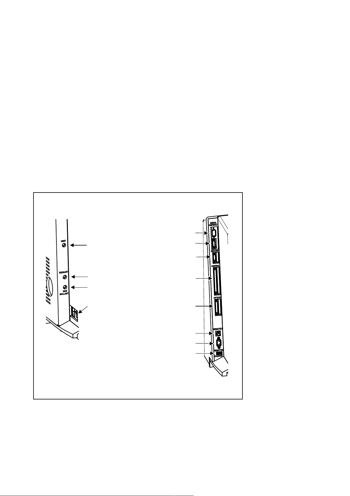
1
2
3
4
5
9
7
11
8
12
6
10
Operation of the PHOENIX L300i where the ground conductor has been left
unconnected is not permissible. The PHOENIX L300i can be damaged when using
the wrong voltage. The voltage must be in the range 230V (+/- 5%), 115V (+/- 5%)
or 100V (+/- 5%) depending on the version.
The mains voltage rating for the PHOENIX L300i can be read off from the name
plate beneath the mains socket
not be changed.
A separate fuse for each of the mains conductors has been integrated into the
mains switch.
The mains voltage is applied to the instrument via the detachable mains cable
which is supplied with the instrument. A mains socket
purpose at the side of the instrument.
Fig. 9/4 at the side. This voltage is fixed and can
Fig. 9/4 is available for this
Installation
Left side:
1. VENT
2. EXHAUST
3. GASBALLAST
4. On / Off switch, mains
socket
Right side:
5. SERIAL
6. CONTROL2
7. RECORD
8. CONTROL
9. OPTION
10. REMOTE1
11. REMOTE2
12. CHARGE (iPad)
Fig. 9 Side views of the PHOENIX L300i
GA10218_002_A7 - 9/2015 - © Oerlikon Leybold 29

Installation
2.4.2 Connection for the Controller Signal and Accessories
OPTION
Digital out (CONTROL)
Caution
Option (Accessories)
The sniffer line SL300 or the partial flow system may be connected to the option
port (
Fig. 9/9):
Contact pins 1 and 3 are fused together with a 0.8 A slow-blow fuse. The amount
of power which can be drawn is limited to 10 W.
The contacts are numbered from bottom to top.
Pin Assignment
1 +24 V, constantly applied, power supply for the Leybold
partial flow valve or sniffer line.
2 GND
3, +24V switched by the PHOENIX L300i for an external
venting valve
4, 5, 6, 7, 8 These pins are used in connection with accessories.
Digital Out (CONTROL)
The following relay outputs Fig. 9/8 are available for further signal processing. The
maximum rating for the relay contacts is 60V AC/1A.
All pins of digital I/O, digital out and recorder must not be connected with voltages higher than 60V DC/25V AC (to grounding equipment conductor) or reach
this threshold.
The contacts are numbered from bottom to top.
Pin Assignment
1 PLC in free selectable
2 PLC in free selectable
3 PLC in free selectable
4 GND
5 to 7 Digital out free selectable, 5 center contact, 6 normally open
contact, 7 normally closed contact
8 to 10 Digital out free selectable
11 to 13 Digital out free selectable
14 to 16 Digital out free selectable
The pin assignment for contacts 8 to 16 follows the same order as for pins 5 to 7.
For further information see chapter 3.5.
GA10218_002_A7 - 9/2015 - © Oerlikon Leybold Vacuum
30
 Loading...