

Page 1

Water Specialist
1” Control Valve Series Model: WS1EI
1.25” Control Valve Series Model: WS1.25EI
Operation and Instruction Manual for OEM Only.
Please Note: This operation and instruction manual is for the training of the
OEM and for the OEM to use to train their customers. This document is not
to be used as the complete system manual.
Page 2

Page 3

WS1EI & WS1.25EI Man u al
Table of Contents
Programming Instructions Refer to 1.5&2L Manual
Control Valve Function and Cycles of Operation Control Valve Function and Cycles of Operation 1 - 2
Drawings and Part Numbers
Front Cover and Drive Assembly Drawings and Part Numbers 1
WS1EI Drive Cap, Pistons and Spacer Stack Drawings and Part Numbers 2a
WS1.25EI Drive Cap, Pistons and Spacer Stack Drawings and Part Numbers 2b
WS1 & WS1.25 Identifi cation Figure Drawings and Part Numbers 2c
FOR INFORMATION COMMON TO ALL 1” & 1.25” CONTROL VALVEaS REFER TO THE WS1&WS1.25 COMMON
INFORMATION MANUAL
The common manual contains the Table of Contents shown below
Other Drawings and Part Numbers
Compliance T able No page number
Injector Cap, Injector Screen, Injector, Plug and O-ring Drawings and Part Numbers 3a
Injector Order Information Drawings and Part Numbers 3b
Injector Graphs US Units: Injector Draw, Slow Rinse and Total Flow Rates Drawings and Part Numbers 3c-3d
Injector Graphs Metric Units: Injector Draw, Slow Rinse and Total Flow Rates Drawings and Part Numbers 3e-3f
Refi ll Flow Control Assembly and Refi ll Port Plug Drawings and Part Numbers 4
Drain Line – 3/4” Drawings and Part Numbers 5
Drain Line – 1” Drawings and Part Numbers 6
Water Meter, Meter Plug and Mixing Valve Drawings and Part Numbers 7
Installation Fitting Assemblies Drawings and Part Numbers 8a – 8b
Bypass Valve Drawings and Part Numbers 9
Flow Diagrams – Service and Backwash Drawings and Part Numbers 10
Flow Diagrams – Downfl ow and Upfl ow Drawings and Part Numbers 11
Flow Diagrams – Rinse and Fill Drawings and Part Numbers 12
WS1 Wrench Drawings and Part Numbers 13
General Information General Information 1
General Warnings (Must appear in OEM’s manual) General Information 1
Specifi cations which must be included in OEM’s Manual General Information 2
Quick Reference Specifi cations General Information 2
Drive Assembly General Information 3
Drive Cap Assembly, Main Piston and Regenerant Piston General Information 3
Spacer Stack Assembly General Information 4
Injector Cap, Screen, Injector Plug and Injector General Information 4
Refi ll Flow Control Assembly or Refi ll Port Plug General Information 4
Drain Line Flow Control and Fitting Assembly General Information 5
Water Meter or Meter Plug General Information 6
Mixing Valve General Information 6
Installation Fitting Assemblies General Information 6
Bypass Valve General Information 7 - 8
Installation Installation 1 - 2
Service Instructions Service Instructions 1 - 5
Troubleshooting Troubleshooting 1 - 2
Limited W arranty Last Page
Page 4

Control Valve Function and Cycles of Operation • Page 1
WS1EI & WS1.25EI Man u al
Control Valve Function and Cycles of Operation
This glass fi lled Noryl1 (or equivalent) fully automatic control valve is designed as the primary control center to direct and regulate
all cycles of a water softener or fi lter. The WS1EI and WS1.25EI control valves are only available in downfl ow regeneration. When
the WS1EI or WS1.25EI control valve is set up as a fi lter, the control valve can be set to perform downfl ow regeneration or simply
backwash. The control valve can be set to regenerate on demand (consumption of a predetermined amount of water) and/or as a
time clock (passage of a particular number of days). The control valve can be set so that a softener can meet the Water Quality
As so ci a tion (WQA) Standard S100 or NSF/ANSI Standard 44 effi ciency rating.
The control valve is compatible with a variety of regenerants and resin cleaners. The control valve is capable of routing the fl ow
of water in the necessary paths to regenerate or backwash water treatment systems. The injector regulates the fl ow of brine or
other regenerants. The control valve regulates the fl ow rates for backwashing, rinsing, and the replenishing of treated water into a
regenerant tank, when applicable.
The control valve uses no traditional fasteners (e.g. screws); instead clips, threaded caps, nuts and snap type latches are used. Caps
and nuts only need to be fi rmly hand tightened because radial seals are used. Tools required to service the valve include one small
blade screw driver, one large blade screw driver, pliers and a pair of hands. A plastic wrench is available which eliminates the need
for screwdrivers and pliers. Disassembly for servicing takes much less time than com pa ra ble products currently on the market.
Control valve in stal la tion is made easy because the distributor tube can be cut 12.7 mm (½”) above to 12.7 mm (½”) below the top
of tank thread. The distributor tube is held in place by an o-ring seal and the control valve also has a bayonet lock feature for upper
distributor baskets.
The AC adapter power pack comes with a 4.6 meter (15 foot) power cord and is designed for use with the control valve. The AC
adapter power pack is for dry location use only.
Table 1 shows the order of the cycles and available time for the WS1EI or WS1.25EI control valve. The WS1EI and WS1.25EI can
be used for downfl ow softener and fi lter applications as well as backwash-only fi lters.
Table 1
Regeneration Cycles and Times
WS1EI & WS1.25EI Cycles of Operation
Cycle
1. Backwash 1
st
(upfl ow)
2. Regenerant Draw/Slow Rinse (downfl ow)
3. Backwash 2
nd
(upfl ow)
4. Fast Rinse (downfl ow)
5. Regenerant Refi ll (with treated water)
Range of times (min.)
1 - 20 or OFF
1 - 99 or OFF
1 - 20 or OFF
1 - 20 or OFF
0.1 - 99.9 or OFF
6. Service (downfl ow)
1
Noryl is a trademark of General Electric.
Page 5

WS1EI & WS1.25EI Man u al
The user can initiate manual regeneration. The user has the option to request the manual regeneration at the delayed regeneration
time or to have the regeneration occur immediately:
1. Pressing and releasing the REGEN button. “ ” will fl ash towards Regen on the display and the regeneration will occur at the
delayed re gen er a tion time. The user can cancel the request by pressing and releasing the REGEN button.
2. Pressing and holding the REGEN button for approximately 3 seconds will immediately start the regeneration. The user cannot
cancel this request, except by resetting the control by pressing NEXT and REGEN buttons simultaneously for 3 seconds.
For additional software features and specifi c setup refer to the 1.5 & 2L manual for this software.
▲
Control Valve Function and Cycles of Operation • Page 2
Page 6
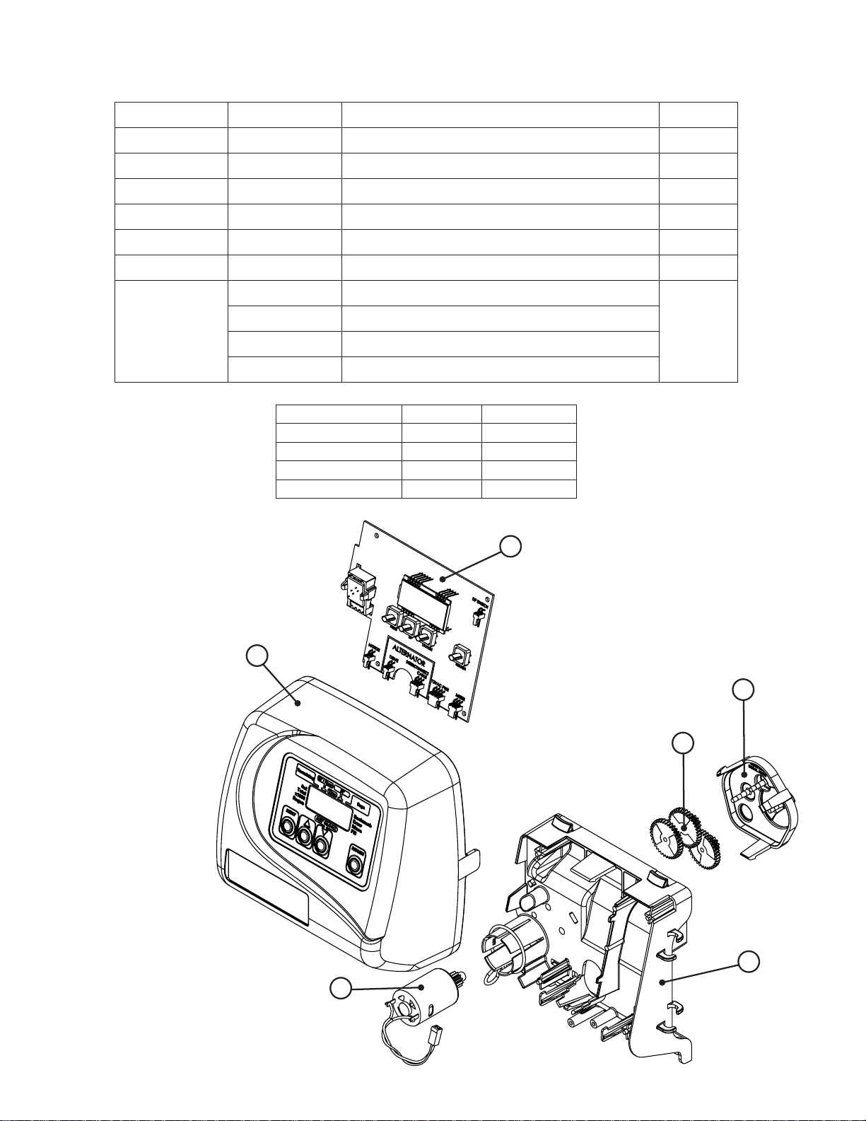
Drawings and Part Numbers • Page 1
EI Front Cover and Drive Assembly
Drawing No. Order No. Description Quantity
1 V3175EI-01 WS1EI FRONT COVER ASSEMBLY 1
2 V3107-01 WS1 MOTOR 1
3 V3106-01 WS1 DRIVE BRACKET & SPRING CLIP 1
4 V3408EI-01 WS1THRU2L EI PC BOARD ALT 1
5 V3110 WS1 DRIVE REDUCING GEAR 12X36 3
6 V3109 WS1 DRIVE GEAR COVER 1
V3186 WS1 AC ADAPTER 110V-12V
WS1EI & WS1.25EI Man u al
Not Shown
V3186EU WS1 AC ADAPTER 220-240V -12V EU
1
V3186UK WS1 AC ADAPTER 220-240V-12V UK
V3186-01 WS1 AC ADAPTER CORD ONL Y
AC Adapter U.S. International
Supply Voltage 120 V AC 230V AC
Supply Frequency 60 Hz 50 Hz
Output Voltage 12 V AC 12 V AC
Output Current 500 mA 500 mA
4
1
6
5
3
2
Page 7
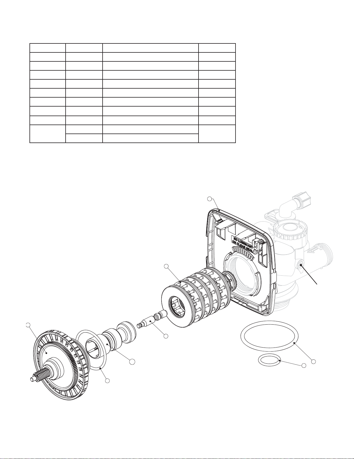
WS1EI & WS1.25EI Man u al
WS1EI Drive Cap Assembly, Downfl ow Piston, Regenerant Piston and Spacer Stack Assembly
Drawing No. Order No. Description Quantity
1 V3005 WS1 Spacer Stack Assembly 1
2 V3004 Drive Cap ASY 1
3 V3178 WS1 Drive Back Plate 1
4 V3011* WS1 Piston Downfl ow ASY 1
5 V3174 WS1 Regenerant Piston 1
6 V3135 O-ring 228 1
7 V3180 O-ring 337 1
8 V3105 O-ring 215 (Distributer Tube) 1
Not Shown
*V3011 is labeled with DN.
Note: The regenerant piston is not used in backwash only applications.
V3001 WS1 Body ASY Downfl ow
V3001-02 WS1 Mixing Valve Body ASY
1
Drawings and Part Numbers • Page 2a
3
1
4b
2
5
4a
4
Black Plug
7
8
6
Page 8
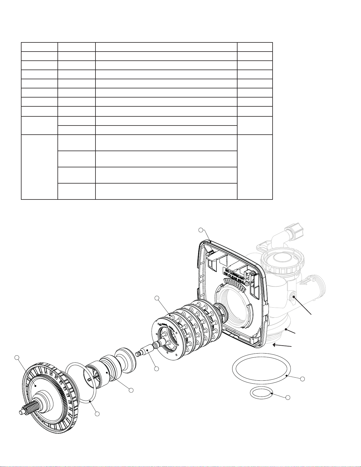
Drawings and Part Numbers • Page 2b
WS1EI & WS1.25EI Man u al
WS1.25EI Drive Cap Assembly, Downfl ow Piston, Regenerant Piston and Spacer Stack Assembly
Drawing No. Order No. Description Quantity
1 V3430 WS1.5 Spacer Stack Assembly 1
2 V3004 Drive Cap ASY 1
3 V3178 WS1 Drive Back Plate 1
4 V3407 WS1.5 Piston Downfl ow ASY 1
5 V3174 WS1 Regenerant Piston 1
6 V3135 O-ring 228 1
7 V3180 O-ring 337 1
8
V3358 O-ring 219 (Distributor Tube Opening 33.5 mm (1.32"))
V3357 O-ring 218 (Distributor Tube Opening 32 mm)
1
V3020 WS1.25 Body ASY Downfl ow
(Distributor Tube Opening 33.5 mm (1.32"))
V3020-01 WS1.25 Mixing Valve Body Downfl ow ASY
Not Shown
V3020-02 WS1.25 Body ASY Downfl ow
(Distributor Tube Opening 33.5 mm (1.32"))
1
(Distributor Tube Opening 32mm)
V3020-03 WS1.25 Mixing Valve Body Downfl ow ASY
(Distributor Tube Opening 32mm)
Note: The regenerant piston is not used in backwash only applications.
1
2
5
3
Grey Plug on all
WS1.25 bodies
*Grey Ring
*Grey Distributor
O-ring retainer
7
4
8
6
*Only for valves that have a
32mm Distributor Tube Opening
Page 9
WS1EI & WS1.25EI Man u al
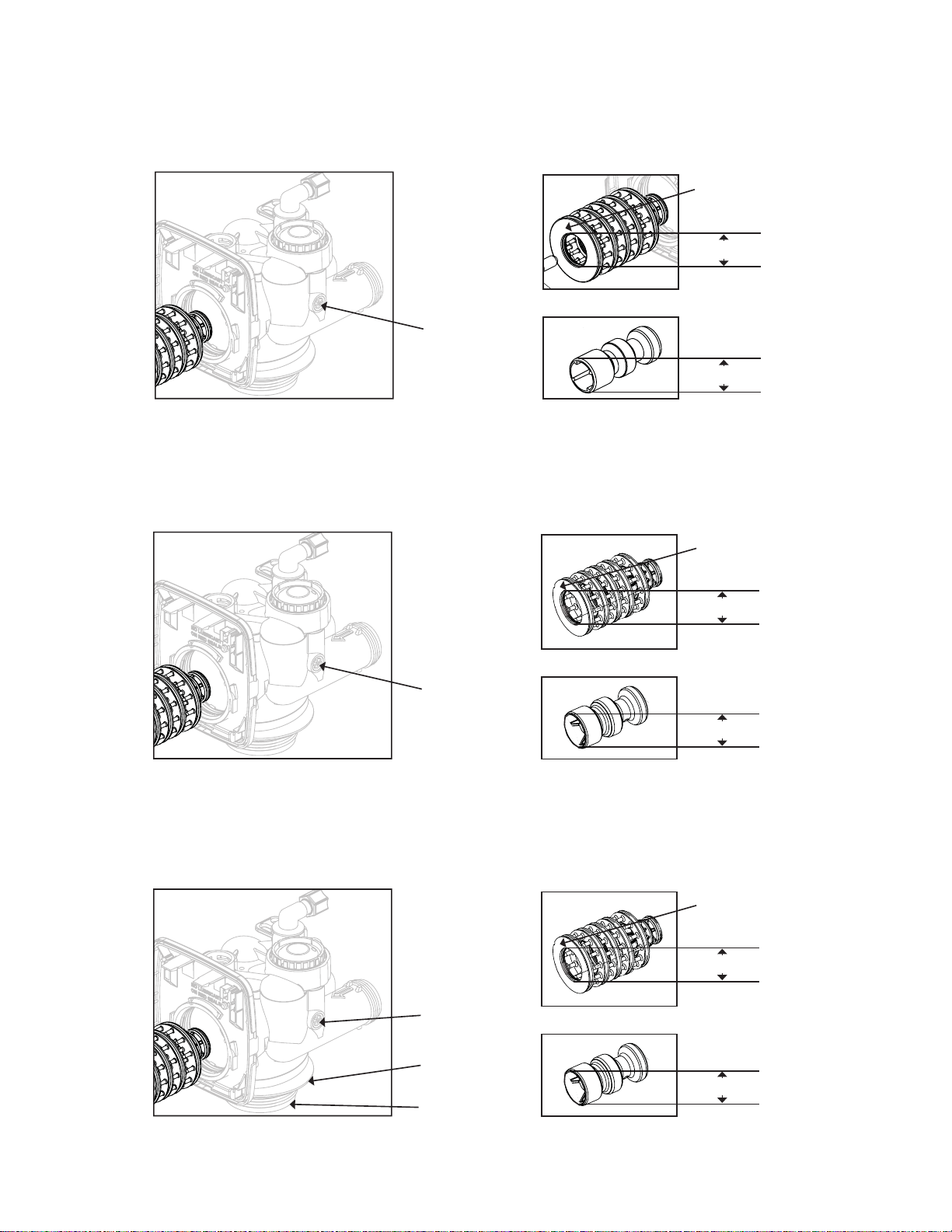
Drawings and Part Numbers • Page 2c
WS1 & WS1.25 Identifi cation Figure
WS1 with 1.050" Distributor Tube Opening Identifi cation
Black Plug
D
Note: The WS1 downfl ow piston is a solid amber color.
WS1.25 with 1.32" Distributor Tube Opening Identifi cation
Spacer Color:
Grey
1.25"
1.25"
Spacer Color:
Black
1.5"
Grey Plug
WS1.25 with 32mm Distributor Tube Opening Identifi cation
Grey Plug
Grey Ring
Grey
Distributor
O-ring
Retainer
1.5"
Spacer Color:
Black
1.5"
1.5"
Page 10

WS1EI & WS1.25EI Man u al
Page 11

WS1EI & WS1.25EI Man u al
FOR INFORMATION COMMON TO ALL 1” & 1.25” CONTROL VALVES REFER TO THE WS1&WS1.25 COMMON
INFORMATION MANUAL
The common manual contains the Table of Contents shown below
Other Drawings and Part Numbers
Compliance T able No page number
Injector Cap, Injector Screen, Injector, Plug and O-ring Drawings and Part Numbers 3a
Injector Order Information Drawings and Part Numbers 3b
Injector Graphs US Units: Injector Draw, Slow Rinse and Total Flow Rates Drawings and Part Numbers 3c-3d
Injector Graphs Metric Units: Injector Draw, Slow Rinse and Total Flow Rates Drawings and Part Numbers 3e-3f
Refi ll Flow Control Assembly and Refi ll Port Plug Drawings and Part Numbers 4
Drain Line – 3/4” Drawings and Part Numbers 5
Drain Line – 1” Drawings and Part Numbers 6
Water Meter, Meter Plug and Mixing Valve Drawings and Part Numbers 7
Installation Fitting Assemblies Drawings and Part Numbers 8a – 8b
Bypass Valve Drawings and Part Numbers 9
Flow Diagrams – Service and Backwash Drawings and Part Numbers 10
Flow Diagrams – Downfl ow and Upfl ow Drawings and Part Numbers 11
Flow Diagrams – Rinse and Fill Drawings and Part Numbers 12
WS1 Wrench Drawings and Part Numbers 13
General Information General Information 1
General Warnings (Must appear in OEM’s manual) General Information 1
Specifi cations which must be included in OEM’s Manual General Information 2
Quick Reference Specifi cations General Information 2
Drive Assembly General Information 3
Drive Cap Assembly, Main Piston and Regenerant Piston General Information 3
Spacer Stack Assembly General Information 4
Injector Cap, Screen, Injector Plug and Injector General Information 4
Refi ll Flow Control Assembly or Refi ll Port Plug General Information 4
Drain Line Flow Control and Fitting Assembly General Information 5
Water Meter or Meter Plug General Information 6
Mixing Valve General Information 6
Installation Fitting Assemblies General Information 6
Bypass Valve General Information 7 - 8
Installation Installation 1 - 2
Service Instructions Service Instructions 1 - 5
Troubleshooting Troubleshooting 1 - 2
Limited W arranty Last Page
Page 12

Revision History:
11/12/07
DRAWINGS AND PART NUMBERS • PAGE 1
4 V3408EI-01 WS1THRU2L EI PC BOARD ALT 1
WS1EI & WS1.25EI Man u al
Form No. V3115EI – Updated 11/12/07
 Loading...