

OEM Optical IVS-CCAM3, IV-CCAM3P Operating Manual

Miniature Color CCD Camera
IVS-CCAM3 / IV-CCAM3P
OPERATING MANUAL
For Customer Use :
Please record the model No. and the serial
No. in the spaces provided below. These
numbers located on the bottom of the
camera.
Keep this manual for future reference.
Model No. Serial No.
This lightning flash with arrowhead
symbol is intended to alert the user to the
presence of uninsulated “dangerous
voltage” within the product’s enclosure
that may be of sufficient magnitude to constitute a
risk of electric shock to persons.
1
CAUTION
RISK OF ELECTRIC SHOCK
DO NOT OPEN
CAUTION : TO REDUCE THE RISK OF ELECTRIC SHOCK, DO NOT REMOVE
COVER (OR BACK). NO USER SERVICEABLE PARTS INSIDE.
REFER SERVICING TO QUALIFIED SERVICE PERSONAL.
This exclamation point symbol is intended to
alert the user to the presence of important
operating and main tenance (servicing)
instructions in the literature accompanying
the appliance.
Due to design modification, data given in this
instruction book are subject to possible change
without prior notice.
WARNING :
TO PREVENT THE RISK OF FIRE OR ELECTRIC
SHOCK HAZARD, DO NOT EXPOSE THIS CAMERA
TO RAIN OR MOISTURE.
Information for USA
This device complies with Part 15 of the
FCC rules. Changes or modifications not
approved by ABC could void the user’s
authority to operate the equipment.

2
Thank you for purchasing this Color CCD camera. Before using this camera, please read this operating
manual carefully to obtain the best result and keep this manual for future reference.
PRECAUTIONS . . . . . . . . . . . . . . . . 3
FEATURES . . . . . . . . . . . . . . . . . . . . 4
NAME AND FUNCTIONS . . . . . . . . . 5
MENU SYSTEM . . . . . . . . . . . . . . . . 7
Menu description . . . . . . . . . . . . . . 8
Main menu . . . . . . . . . . . . . . . . . . 9
Lens . . . . . . . . . . . . . . . . . . . . . . 10
AGC on/off . . . . . . . . . . . . . . . . . 10
Electronic shutter control . . . . . . . .11
White balance control . . . . . . . . . .12
Back light compensation . . . . . . . .13
Text display . . . . . . . . . . . . . . . . . .14
Special menu . . . . . . . . . . . . . . . .15
LENS INSTALLATION . . . . . . . . . . . 19
Mounting a lens . . . . . . . . . . . . . . 20
Back-focus adjustment . . . . . . . . . 21
SPECIFICATIONS . . . . . . . . . . . . . . 22
SUPPLIED ACCESSORIES . . . . . . . 23
CONTENTS

3
PRECAUTIONS
Operating
Ø
Before using, make sure of power supply and
connection of video output.
Power supplied without voltage stabilization or the
voltage maintained at 12V±10% DC may cause
damage.
Ø
While operating, if any abnormal condition or a malfunction is observed, stop using the camera immediately and then call your local dealer.
Handling
Ø
Do not disassemble the camera and never touch
parts inside the camera.
Ø
Do not drop the camera or subject it to shocks and
vibrations to avoid possible damage.
Ø
When attaching or removing the lens, handle with
care in order that moisture and dust does not enter
the camera.
Ø
Do not shoot any source of bright light. if the object
contains very bright areas, bright vertical or horizontal lines may appear on the screen. This is
called "smear", a phenomenon which often occurs
with solid-state pickups, and is not a malfunction.
Installation and storage
Ø
Do not point the camera at the sun. This could
damage the camera whether it is operating or not.
Ø
Do not install the camera where the temperature could
exceed the allowable range.
Be sure the ambient temperature is less than 40°C for
long term continuous operation.
Ø
Avoid installing in humid or dusty places.
Ø
Avoid installing in places where there is radiation. This
could damage CCD and other components and
cause malfunction.
Ø
Avoid installing in places where there are strong magnetic fields and electric signals.
Ø
Avoid installing in places where the camera would be
subject to strong vibrations.
Ø
Never expose the camera to rain and water.
Cleaning
Turn the power off and wipe off the dirt with dry soft cloths. If it
is extremely dirty, use furniture cleaning tissue. Do not use
alcohols, petroleum distillates, liquid cleaners or sprays.
Daily check
Make daily check for proper operation for surveillance use. In
order to maintain normal operation, the output of camera
should be checked by user everyday for a clear and focused
picture.

4
FEATURES
High sensitivity
1/3” 470,000 pixels for PAL CCD with on-chip micro
lenses and low noise signal processing circuit provide
high sensivity down to 0.8 lux(F1.2).
High quality image
Ø
High resolution, high sensitivity design for
a horizontal resolution of 470 TV lines. (460TV
lines for PAL)
Ø
High quality image is obtained by digital signal
processing with optimization of control program
and image correction algorithm.
Back light compensation
When strong light entering the scene background such
as from a spotlight or window, back light compensation
function automatically adjust the video level so as to
preserve visibility in important sections of the image.
White balance
Three control modes of auto-tracking preset and
manual white blance can be selected according to
conditions.
Iris function
Provide a drive output for video iris lens.
Also built-in electronic shutter to allow 11 shutter
speeds up to 1/100,000 sec.
CCD iris function automatically set the brightness of
the picture by changing the shutter speed of the
camera according to the incident light when using a
manual iris lens.
Other versatile functions
Ø
Text display function of up to 24 characters.
Ø
Separated Y/C video signal output connector.
Ø
Special menu functions for gamma, color adj.,
contrast, sharpness, preset.
Ø
Use either C or CS mount lenses.
5
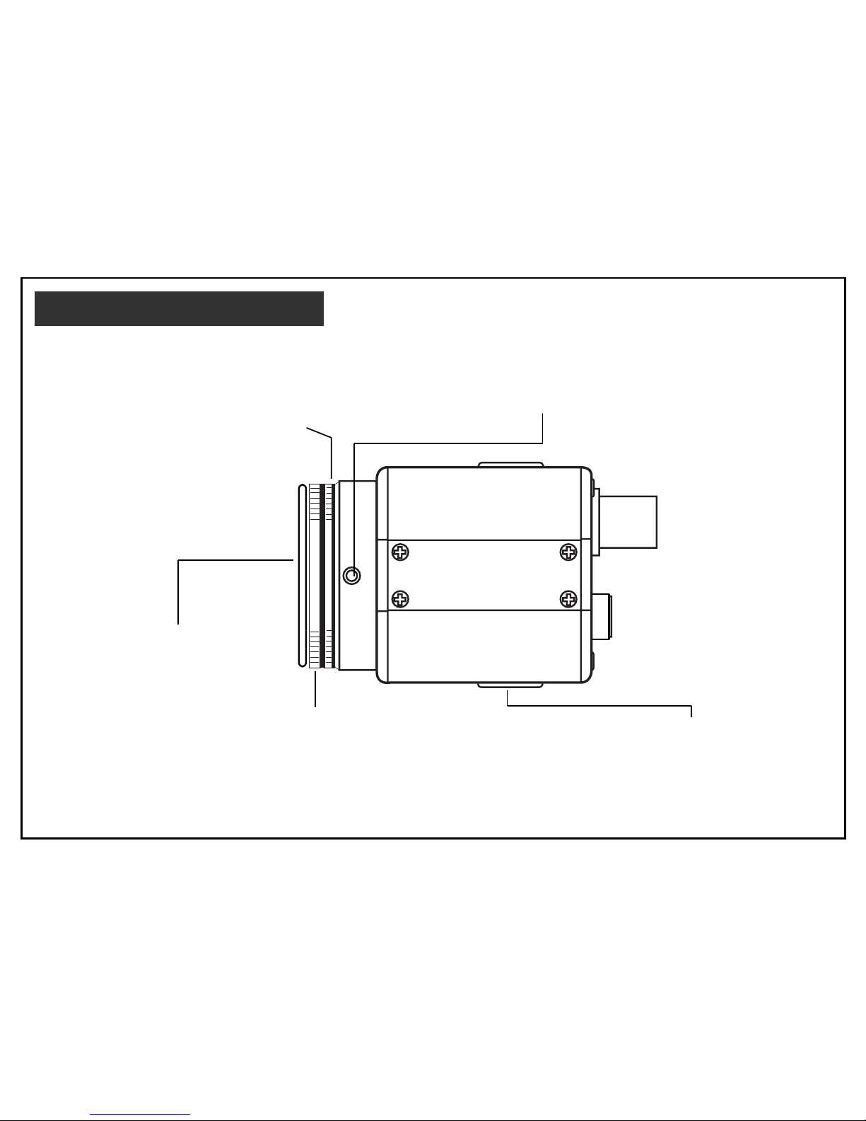
NAME AND FUNCTIONS
COLOR CCD CAMERA
DIGITAL
Lens mount
Mount for installing the lens. C-mount
lens can be used when C-mount adapter
is attached and CS-mount lens can be
used when it is removed.
Back-focus screw
A screw is provided to fix the lens mount.
See page 21.
Lens mount cap
Be sure to cap the lens mount
when the lens is not mounted.
Tripod mounting base
Mounting base for installing the
camera.
C-mount adapter
To mount a C-mount lens. And remove to
mount a CS-mount lens. Turn counterclockwise to remove it. Also refer to page 20.
6
VIDEO
PWR
LENS
S-VIDEO
12VDC
SET
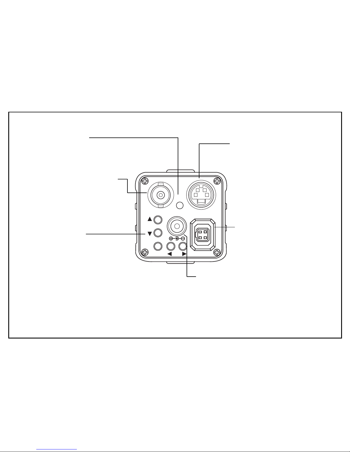
Video output connector
BNC connector that outputs
a composite video sihnal.
Power indicator
Lights up when the camera is
powered.
S-VIDEO connector
Output connector seperated
Y/C video signal.
Connector to the S-VIDEO
input connector of video
monitor. See page 19.
Setup buttons
When use setting up and
adjusting the camera with
reference to the on-screen
menu. See page 8.
Power input terminal
Connect to a DC12V power power
source.
(Be sure not to connect the power
source until all other connections are
completed.)
Lens connector
When using an auto-iris lens,
connect the lens cable to this
connector. See page 19.
7
GENERAL
The menu system can activate all the features and
option of the camera.
The menus are superimposed on the image
displayed on the screen. The commands can open
other menus, toggle options, or change variable
parameters.
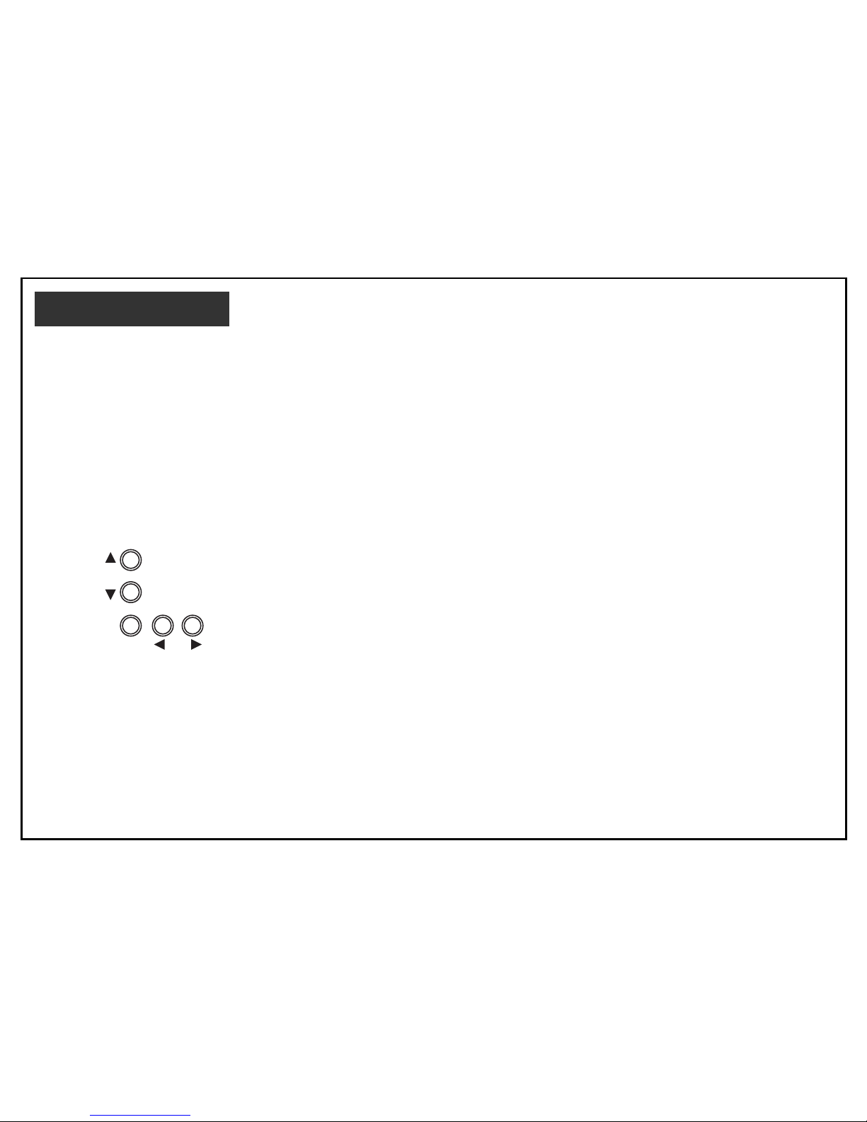
MENU OPERATION
Five rear panel Setup buttons are used to shift the
cursor and select items from the menus.
①
Up button : Shift the cursor upwards.
➁
Down button : Shift the cursor downwards.
➂
Left button : Shift the cursor toward the left.
➃
Right button : Shift the cursor toward the right.
➄
Set button : To display the main menu or
check the setting and proceed to
the next item.
The camera settings and adjustments can be changed to
accommodate usage conditions.
When connected to a monitor, convenient on-screen
menus facilitate checking and changing the settings and
adjustments.
A brief help lines is often presented on the screen below
the list of commands.
The complete set of current parameters is saved, and will
be loaded each time turn on the camera until the next time
change the setup.
The setting menus are illustrated on the next page.
MENU SYSTEM
SET
1
2
534
Setup buttons
 Loading...