

Page 1

Miniature Color CCD Camera
IVS-CCAM3 / IV-CCAM3P
OPERATING MANUAL
For Customer Use :
Please record the model No. and the serial
No. in the spaces provided below. These
numbers located on the bottom of the
camera.
Keep this manual for future reference.
Model No. Serial No.
Page 2
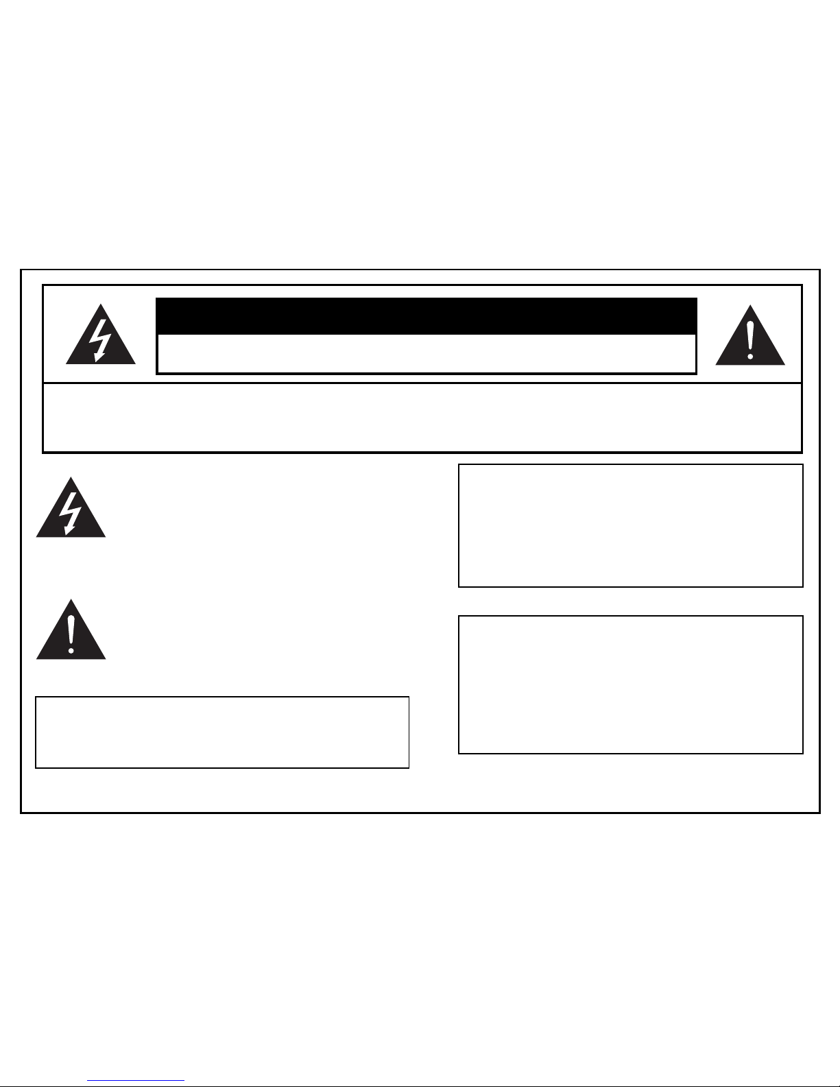
This lightning flash with arrowhead
symbol is intended to alert the user to the
presence of uninsulated “dangerous
voltage” within the product’s enclosure
that may be of sufficient magnitude to constitute a
risk of electric shock to persons.
1
CAUTION
RISK OF ELECTRIC SHOCK
DO NOT OPEN
CAUTION : TO REDUCE THE RISK OF ELECTRIC SHOCK, DO NOT REMOVE
COVER (OR BACK). NO USER SERVICEABLE PARTS INSIDE.
REFER SERVICING TO QUALIFIED SERVICE PERSONAL.
This exclamation point symbol is intended to
alert the user to the presence of important
operating and main tenance (servicing)
instructions in the literature accompanying
the appliance.
Due to design modification, data given in this
instruction book are subject to possible change
without prior notice.
WARNING :
TO PREVENT THE RISK OF FIRE OR ELECTRIC
SHOCK HAZARD, DO NOT EXPOSE THIS CAMERA
TO RAIN OR MOISTURE.
Information for USA
This device complies with Part 15 of the
FCC rules. Changes or modifications not
approved by ABC could void the user’s
authority to operate the equipment.
Page 3

2
Thank you for purchasing this Color CCD camera. Before using this camera, please read this operating
manual carefully to obtain the best result and keep this manual for future reference.
PRECAUTIONS . . . . . . . . . . . . . . . . 3
FEATURES . . . . . . . . . . . . . . . . . . . . 4
NAME AND FUNCTIONS . . . . . . . . . 5
MENU SYSTEM . . . . . . . . . . . . . . . . 7
Menu description . . . . . . . . . . . . . . 8
Main menu . . . . . . . . . . . . . . . . . . 9
Lens . . . . . . . . . . . . . . . . . . . . . . 10
AGC on/off . . . . . . . . . . . . . . . . . 10
Electronic shutter control . . . . . . . .11
White balance control . . . . . . . . . .12
Back light compensation . . . . . . . .13
Text display . . . . . . . . . . . . . . . . . .14
Special menu . . . . . . . . . . . . . . . .15
LENS INSTALLATION . . . . . . . . . . . 19
Mounting a lens . . . . . . . . . . . . . . 20
Back-focus adjustment . . . . . . . . . 21
SPECIFICATIONS . . . . . . . . . . . . . . 22
SUPPLIED ACCESSORIES . . . . . . . 23
CONTENTS
Page 4

3
PRECAUTIONS
Operating
Ø
Before using, make sure of power supply and
connection of video output.
Power supplied without voltage stabilization or the
voltage maintained at 12V±10% DC may cause
damage.
Ø
While operating, if any abnormal condition or a malfunction is observed, stop using the camera immediately and then call your local dealer.
Handling
Ø
Do not disassemble the camera and never touch
parts inside the camera.
Ø
Do not drop the camera or subject it to shocks and
vibrations to avoid possible damage.
Ø
When attaching or removing the lens, handle with
care in order that moisture and dust does not enter
the camera.
Ø
Do not shoot any source of bright light. if the object
contains very bright areas, bright vertical or horizontal lines may appear on the screen. This is
called "smear", a phenomenon which often occurs
with solid-state pickups, and is not a malfunction.
Installation and storage
Ø
Do not point the camera at the sun. This could
damage the camera whether it is operating or not.
Ø
Do not install the camera where the temperature could
exceed the allowable range.
Be sure the ambient temperature is less than 40°C for
long term continuous operation.
Ø
Avoid installing in humid or dusty places.
Ø
Avoid installing in places where there is radiation. This
could damage CCD and other components and
cause malfunction.
Ø
Avoid installing in places where there are strong magnetic fields and electric signals.
Ø
Avoid installing in places where the camera would be
subject to strong vibrations.
Ø
Never expose the camera to rain and water.
Cleaning
Turn the power off and wipe off the dirt with dry soft cloths. If it
is extremely dirty, use furniture cleaning tissue. Do not use
alcohols, petroleum distillates, liquid cleaners or sprays.
Daily check
Make daily check for proper operation for surveillance use. In
order to maintain normal operation, the output of camera
should be checked by user everyday for a clear and focused
picture.
Page 5

4
FEATURES
High sensitivity
1/3” 470,000 pixels for PAL CCD with on-chip micro
lenses and low noise signal processing circuit provide
high sensivity down to 0.8 lux(F1.2).
High quality image
Ø
High resolution, high sensitivity design for
a horizontal resolution of 470 TV lines. (460TV
lines for PAL)
Ø
High quality image is obtained by digital signal
processing with optimization of control program
and image correction algorithm.
Back light compensation
When strong light entering the scene background such
as from a spotlight or window, back light compensation
function automatically adjust the video level so as to
preserve visibility in important sections of the image.
White balance
Three control modes of auto-tracking preset and
manual white blance can be selected according to
conditions.
Iris function
Provide a drive output for video iris lens.
Also built-in electronic shutter to allow 11 shutter
speeds up to 1/100,000 sec.
CCD iris function automatically set the brightness of
the picture by changing the shutter speed of the
camera according to the incident light when using a
manual iris lens.
Other versatile functions
Ø
Text display function of up to 24 characters.
Ø
Separated Y/C video signal output connector.
Ø
Special menu functions for gamma, color adj.,
contrast, sharpness, preset.
Ø
Use either C or CS mount lenses.
Page 6
5
NAME AND FUNCTIONS
COLOR CCD CAMERA
DIGITAL
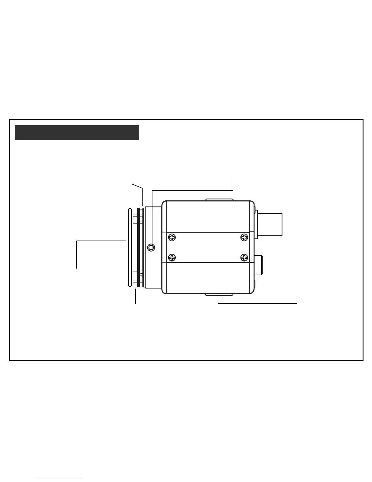
Lens mount
Mount for installing the lens. C-mount
lens can be used when C-mount adapter
is attached and CS-mount lens can be
used when it is removed.
Back-focus screw
A screw is provided to fix the lens mount.
See page 21.
Lens mount cap
Be sure to cap the lens mount
when the lens is not mounted.
Tripod mounting base
Mounting base for installing the
camera.
C-mount adapter
To mount a C-mount lens. And remove to
mount a CS-mount lens. Turn counterclockwise to remove it. Also refer to page 20.
Page 7
6
VIDEO
PWR
LENS
S-VIDEO
12VDC
SET
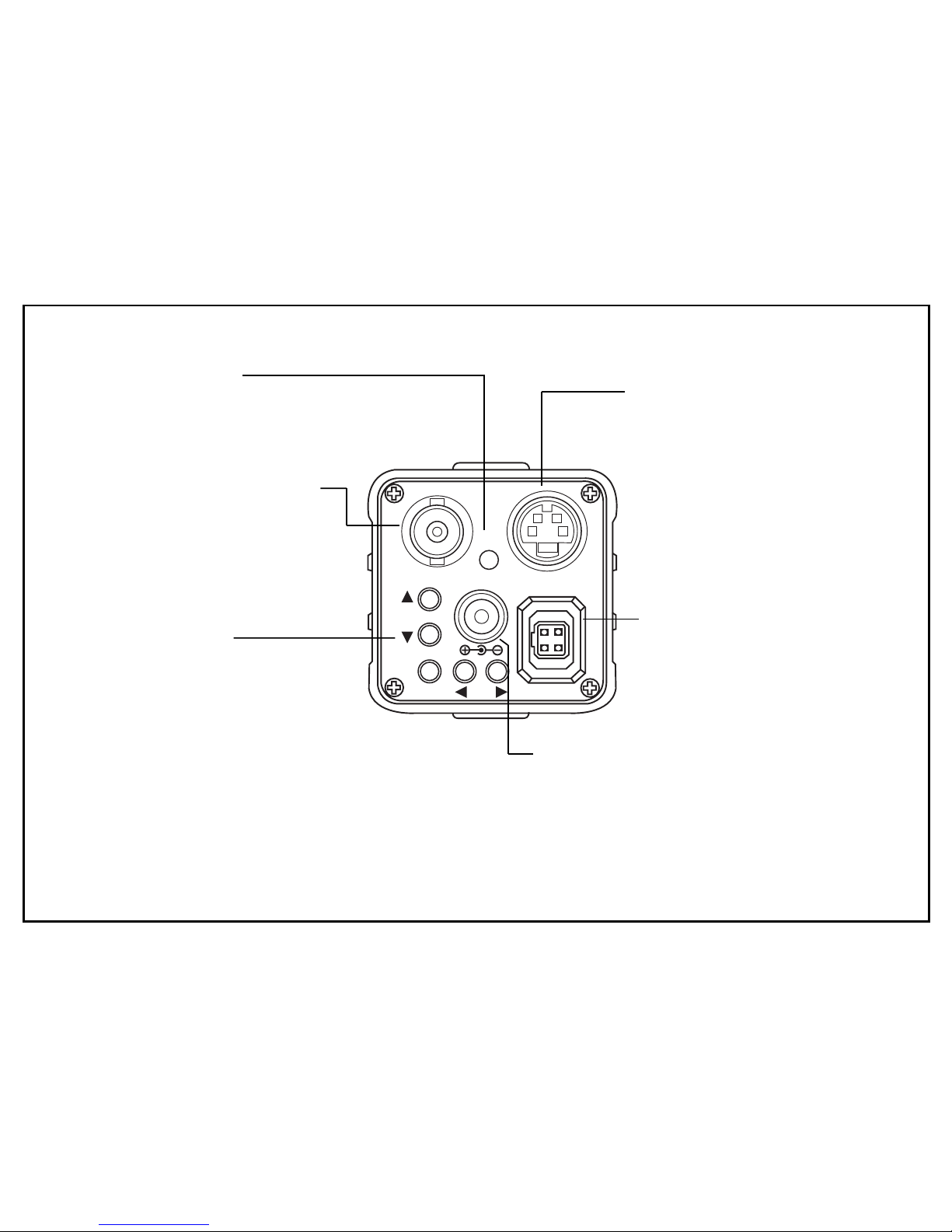
Video output connector
BNC connector that outputs
a composite video sihnal.
Power indicator
Lights up when the camera is
powered.
S-VIDEO connector
Output connector seperated
Y/C video signal.
Connector to the S-VIDEO
input connector of video
monitor. See page 19.
Setup buttons
When use setting up and
adjusting the camera with
reference to the on-screen
menu. See page 8.
Power input terminal
Connect to a DC12V power power
source.
(Be sure not to connect the power
source until all other connections are
completed.)
Lens connector
When using an auto-iris lens,
connect the lens cable to this
connector. See page 19.
Page 8
7
GENERAL
The menu system can activate all the features and
option of the camera.
The menus are superimposed on the image
displayed on the screen. The commands can open
other menus, toggle options, or change variable
parameters.
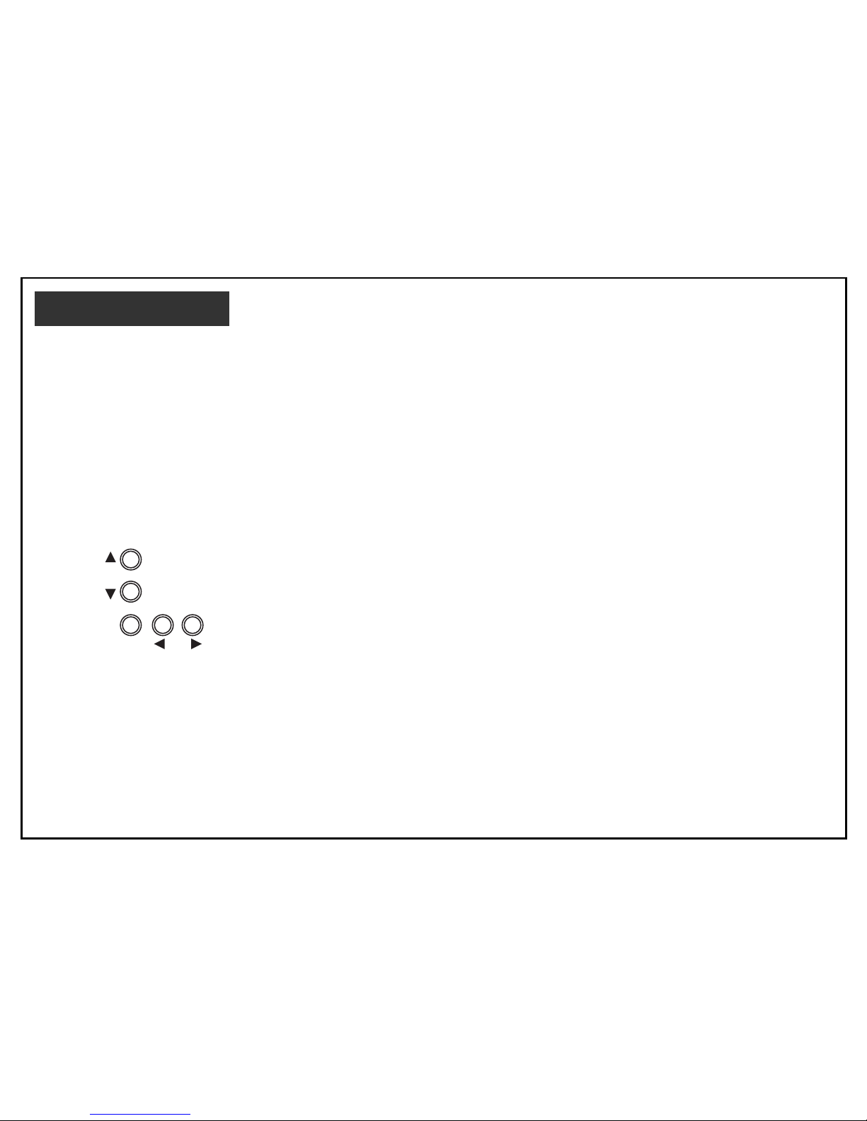
MENU OPERATION
Five rear panel Setup buttons are used to shift the
cursor and select items from the menus.
①
Up button : Shift the cursor upwards.
➁
Down button : Shift the cursor downwards.
➂
Left button : Shift the cursor toward the left.
➃
Right button : Shift the cursor toward the right.
➄
Set button : To display the main menu or
check the setting and proceed to
the next item.
The camera settings and adjustments can be changed to
accommodate usage conditions.
When connected to a monitor, convenient on-screen
menus facilitate checking and changing the settings and
adjustments.
A brief help lines is often presented on the screen below
the list of commands.
The complete set of current parameters is saved, and will
be loaded each time turn on the camera until the next time
change the setup.
The setting menus are illustrated on the next page.
MENU SYSTEM
SET
1
2
534
Setup buttons
Page 9
8
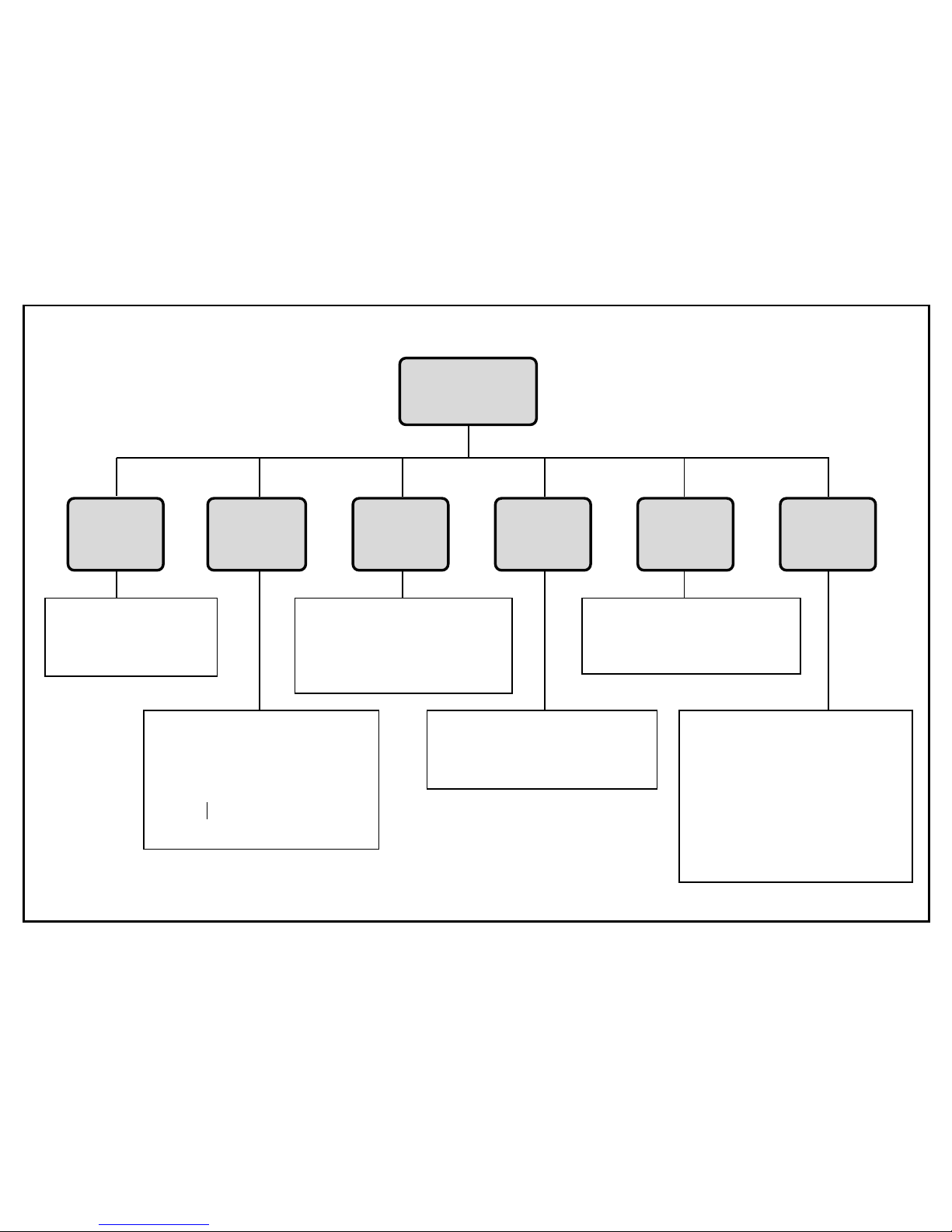
Menu Description
MAIN MENU
(page 8)
AGC
(page 10)
SHUTTER
(page 11)
WHITE
BALANCE
(page 12)
BACK
LIGHT
(page 13)
TEXT
DISPLAY
(page 14)
SPECIAL
MENU
(page 15)
AGC on/off control
H
On
H
Off
White balance control
H
Auto-tracking (ATW)
H
Preset (AWC)
H
Manual (R/B adjust)
Text display
H
Off
H
On (Text generation)
Shutter mode select
H
Auto
H
Manual
(1/60 ~ 1/100,000sec)
(1/50 PAL)
Back light compensation
H
Off
H
On (Zone select)
Special menu
Ø
Gamma
Ø
Color adjustment
Ø
Sharpness (low/high)
Ø
Contrast
Ø
Brightness
Ø
Fickerless
Ø
Preset
Page 10

9
MAIN Menu
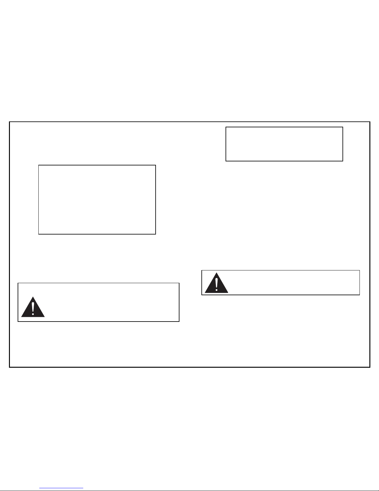
1) Press the Set button to display the main menu on the
monitor screen.
2) Check the present settings at the main menu.
Mainmenu
3) If changes are unnecessary, shift the cursor to the END
position and press the Set button to return the normal
video screen.
4) When a setting is changed by pressing the Setup
buttons, the new setting is stored in the internal
memory by pressing the Set button with position the
cursor at End. Afterwards, when the camera power is
cut off and returned, operation pro ceeds at the most
recent settings.
MAIN MENU
➔ LENS : VIDEO
AGC : ON
Shutter : OFF
White Balance : ATW
Back Light : OFF
Text Display : OFF
Special Menu
End
Note :
In absence of button operation, the menu
display is extinguished automatically in about
60 seconds.
Page 11

10
Lens
1) Press the Set button to display the main menu on the
monitor screen.
2) Position the cursor at LENS and use the left or right
button to toggle between video and MANUAL When
using the manual iris, set the LENS mode according to
the lens type.
AGC on/off
1) Press the Set button to display the main menu.
2) Position the cursor at AGC and press the left or right
button to setting the AGC off.
3) Press the left or right button again, the AGC setting is
returns to AGC on.
At the AGC on setting, camera’s sensitivity is
automatically increased when the level of ambient
light drops.
MAIN MENU
➔ LENS : VIDEO
AGC : ON
Shutter : OFF
White Balance : ATW
Back Light : OFF
Text Display : OFF
Special Menu
End
MAIN MENU
LENS : VIDEO
➔ AGC : OFF
Shutter : OFF
White Balance : ATW
Back Light : OFF
Text Display : OFF
Special Menu
End
Note :
DC type auto iris lens do not work with this
camera.
Page 12
11
Electronic shutter control
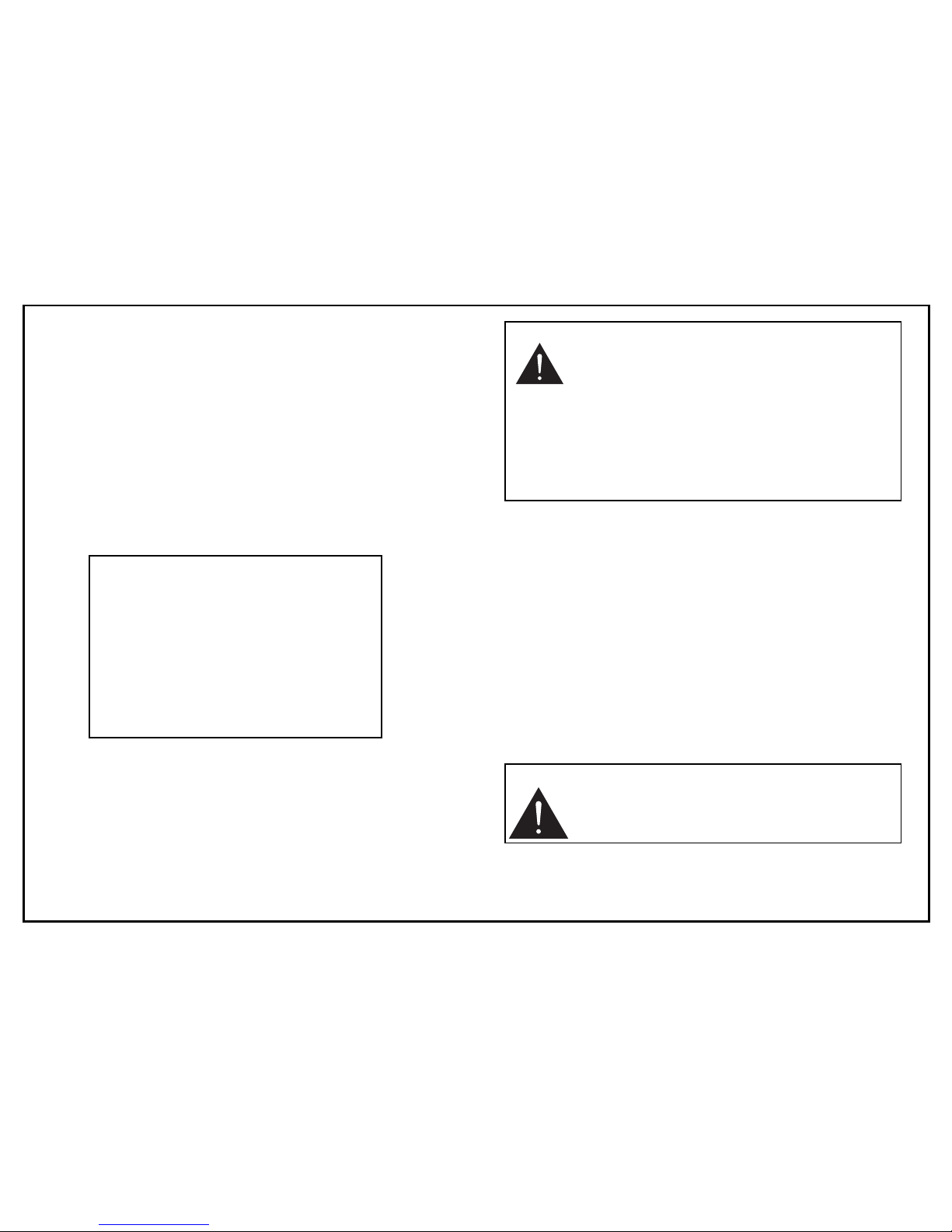
1) Press the Set Button to display the main menu.
2) Position the cursor at SHUTTER, and press the left or
right button to setting the manual shutter.
AUTO Mode
When using the manual iris lens, the brightness of the
picture image will be fixed by setting this auto mode, as
the shutter speed is automatically varied according to
the incident light.
MANUAL Mode
1) Press the Set button to set the manual shutter speed
when position the cursor at SHUTTER and shutter mode
is manual.
2) Press the left or right direction button to select a shutter
speed from 1/60 to 1/100,000 sec.
Left button (ascending sequence) ;
1/60 ➔1/100 ➔1/120 ➔1/250 ➔1/500 ➔1/1000
➔
1/2000 ➔1/4000 ➔1/10000 ➔1/30000➔1/50000
➔
1/100000 ➔1/60
Right button (descending sequence) ;
1/100000 ➔1/50000 ➔1/30000 ➔1/10000
➔
1/4000 ➔1/2000 ➔1/1000 ➔1/500 ➔1/250
➔
1/120 ➔1/100 ➔1/60 ➔1/100000
After setting, press the Set button to return to main menu.
MAIN MENU
LENS : VIDEO
AGC : ON
➔ Shutter : OFF
White Balance : ATW
Back Light : OFF
Text Display : OFF
Special Menu
End
MANUALSHUTTER
➔ Shutter Speed : 1/60
Press SET to Main Menu
Note :
Outdoor illumination levels may exceed 150,000
lux, which is outside the range that can be
controlled by the electronic shutter. For proper
operation of electronic shutter, If illumination
levels ex ceed 10,000 lux, use a auto-iris lens.
Note :
DC type auto iris lenses are doesn’t
work at this camera.
Page 13
12
WHITE BALANCE CONTROL
1) Press the Set button to display the main menu on the
monitor screen.
2) Position the cursor at WHITE BALANCE and press the
left or right button to change the white balance control
mode.
Three white balance control modes can be selected
according to conditions.
When press the left or right button again, white balance
control will be changed the next mode.
ATW (Auto-tracking white balance)
The white balance mode is set to auto-tracking white
balance.
This mode is accepted different types of lighting using
an automatic tracking system and automatically controlled
in the color temperature range of 2400K to 10000K.
AWC (Preset white balance)
Arrange to have a white object present in the scene
and press the Set button to set the Preset white
balance, when position the cursor at WHITE BALANCE
and the mode is AWC.
Setting the preset white balance takes several seconds
and setting is completed when display the message of
" white balance completed " on the screen. If not
completed in about 5 seconds, then again press the
Set button.
MAIN MENU
LENS : VIDEO
AGC : ON
Shutter : OFF
➔ White Balance : ATW
Back Light : OFF
Text Display : OFF
Special Menu
End
Note :
The ATW mode may not function properly in
the following cases.
In such a case, set to the "manual" mode.
Ø
When shooting with non-standard lighting or lighting
with a color temperature that exceeds the range of
the camera.
Ø
When a large part of the scene is occupied by a
single color or a completely red or blue background.
Note :
In order to avoid failure of AWC mode setting,
do not move the camera or the object until the
message of "white balance completed"
appear.
Page 14
13
MANUAL (Manual white balance)
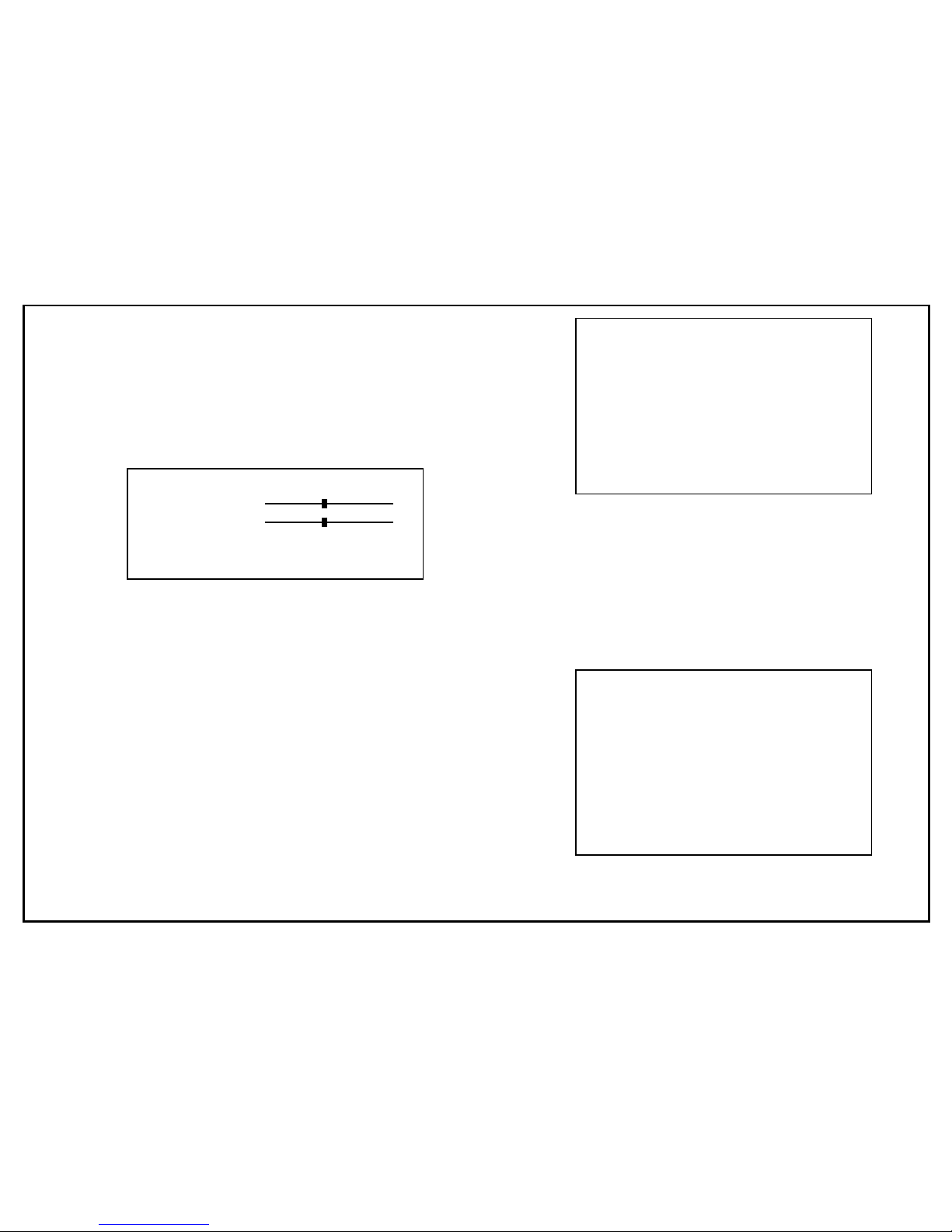
1) Press the Set button to setting Manual white balance
when position the cursor at WHITE BALANCE and
the mode is MANUAL.
2) Press the left, right, up, down direction buttons to
control the Red/Blue gain.
Gain level is indicate from 0 to 20.
After setting, press the Set button to return to main
menu.
Back light compensation
Strong light, such as from a spotlight or window, entering the
scene background causes the lens iris to close, thereby
possibly obscuring desired portions of the scene. Back light
compensation functions automatically adjust the video level so
as to preserve visibility in important sections of the scene.
1) Press the Set button to display the main menu.
2) Position the cursor at BACK LIGHT and press the left
or right button to setting the back light on.
3) Press the left or right button again, back light setting
returns to off.
BLC ZONE SETTING
Backlight control use 6 sensing zones.
The BLC zone setting is activated on the screen by left or
right button to allow the most suitable area to be selected
while observing the monitor. Press the Set button to select
BLC zone when position the cursor at BACK LIGHT and
back light mode is on.
MAIN MENU
LENS : VIDEO
AGC : ON
Shutter : OFF
White Balance : ATW
➔ Back Light : ON
Text Display : OFF
Special Menu
End
BLC ZONE SET
➔ Zone Display
Zone 1 : OFF
Zone 2 : OFF
Zone 3 : OFF
Zone 4 : OFF
Zone 5 : OFF
Zone 6 : OFF
Press SET to View Zone
MANUAL WHITE BALANCE
➔ Red 00
Blue 00
Press SET to Main Menu
Position the cursor at Zone display and press the set
button to view zone.
Page 15
14
Decide a BLC zone number for desired portions of the scene.
1) Press the Set button to display the BLC zone set.
2) Press the up, down direction buttons to move the
cursor to desired BLC zone.
3) Press the left, right direction buttons to setting the
sensing zone which want to preserve visibility in
important section of the scene.
After setting, press the Set button to return to main
menu.
Text display
1) Press the Set button to display the main menu on the
monitor screen.
2) Position the cursor at TEXT DISPLAY and press the left
or right button to setting the text display on.
3) Press the left or right button again, text display setting
returns to off.
TEXT GENERATION
A maximum of 24 alphanumeric characters (1 line) can be
displayed on the screen.
1) Press the Set button to text generation when position
the cursor at TEXT DISPLAY and text display mode
is on.
2) Press the left, right, up, down direction buttons for
selecting characters.
Text is generated when press the Set button for
selected each character.
MAIN MENU
LENS : VIDEO
AGC : ON
Shutter : OFF
White Balance : ATW
Back Light : OFF
➔ Text Display : ON
Special Menu
End
BLC ZONE SET
Zone Display
➔ Zone 1 : OFF
Zone 2 : OFF
Zone 3 : OFF
Zone 4 : OFF
Zone 5 : OFF
Zone 6 : ON
Press SET to Main Menu
Zoom 1
off
Zoom 2
off
Zoom 3
off
Zoom 4
off
Zoom 5
off
Zoom 6
off
Zoom 5
off
Page 16
15
TEXT LOCATION
1) Press the Set button for setting text location when
position the cursor at POS in the Text generation
menu.
2) Press the left, right, up, down direction buttons to
move the text location.
After setting, press the Set button to return to main
menu.
Special Menu
The special menu function allows to change the video
output qualities to match the particular applications.
1) Press the Set button to display the main menu.
2) Position the cursor at SPECIAL MENU and press the
Set button to display the special menu.
Ø
GAMMA
1) Press the Set button to text generation when position the cursor at TEXT DISPLAY and text display
mode is on.
2) Press the left, right, up, down direction buttons for
selecting characters.
SPECIAL MENU
➔ Gamma
Color Adj.
Sharpness : LOW
Contrast : OFF
Brightness
Flickerless : OFF
Preset
End
Camera 1
to Locate, then SET
TEXT GENERATION
ABCDEFGHIJKLMNOPQRS
TUVWXYZabcdefghijkl
mnopqstuvwxyz12345
67890.,’ :+-~/✻ #()<>
BLK CLR POS END
_
SPECIAL MENU
Page 17
16
Gamma level can be selected to maximum 32 steps according
to required conditions.
Default set of Gamma value is 0.45 when activating the Preset
function in Special Menu or setting from factory.
Ø
COLOR ADJUSTMENT
1) Position the cursor at COLOR ADJ. and press the Set
button for color adjustment.
2) Press the left, right, up, down direction buttons to
control the color phase and level.
After setting, press the Set button to return to special menu.
GAMMA ADJUSTEMENT
➔ Level 14
Level gamma value
14 : 0.45
00 : 1
Press SET to Return
SPECIAL MENU
Gamma
➔ Color Adj.
Sharpness : LOW
Contrast : OFF
Brightness
Flickerless : OFF
Preset
End
COLOR ADJUSTMENT
➔ Phase 00
Level 00
Press SET to Return
Page 18
17
Ø
SHARPNESS
1) Position the cursor at SHARPNESS and press the
left or right button for setting the sharpness HIGH.
2) Press the left or right button again, the sharpness
setting returns to LOW.
Ø
CONTRAST
If strong illumination such as a spotlight or outdoor light
is present in the background, causing the scene to
darken.
By setting the contrast compensation function, the dark
areas are enhanced, and brightened the image.
1) Position the cursor at CONTRAST and press the left
or right button for setting the contrast compensation
function to ON.
2) Press the Set button again, the contrast compensation function returns to off.
Ø
BRIGHTNESS
1) Position the cursor at BRIGHTNESS and press the
Set button for setting the brightness.
2) Press the left, right direction button for setting the
brightness level.
After setting, press the Set button to return to special
menu.
SPECIAL MENU
Gamma
Color Adj.
Sharpness : LOW
➔ Contrast : ON
Brightness
Flickerless : OFF
Preset
End
SPECIAL MENU
Gamma
Color Adj.
➔ Sharpness : HIGH
Contrast : OFF
Brightness
Flickerless : OFF
Preset
End
BRIGHTNESS
➔ Level 10
Press SET to Return
Page 19

18
Ø
FLICKERLESS
If the camera is used with 50 Hz fluorescent lighting,
and there is flickering on the monitor.
In this case, set the FLICKERLESS mode to ON.
Otherwise it should be set to off.
1) Position the cursor at FLICKERLESS and press the
left or right direction button for setting the flickerless
on.
2) Press the left or right button again, the flickerless setting is return to off.
Ø
PRESET
This function is useful when the camera is used the
frequently changed setup conditions.
Preset mode provide the best image under the normal
condition by factory setup.
1) When position the cursor at PRESET, " Press SET to
Factory Set" message will be displayed on the
screen.
2) Position the cursor at PRESET and press the Set
button to perform the preset function.
" Factory Setup Completed " message will be
displayed on the screen and the message is
extinguished automatically in about 5 sec.
SPECIAL MENU
Gamma
Color Adj.
Sharpness : LOW
Contrast : OFF
Brightness
➔ Flickerless : ON
Preset
End
SPECIAL MENU
Gamma
Color Adj.
Sharpness : LOW
Contrast : OFF
Brightness
Flickerless : OFF
➔ Preset
End
Page 20
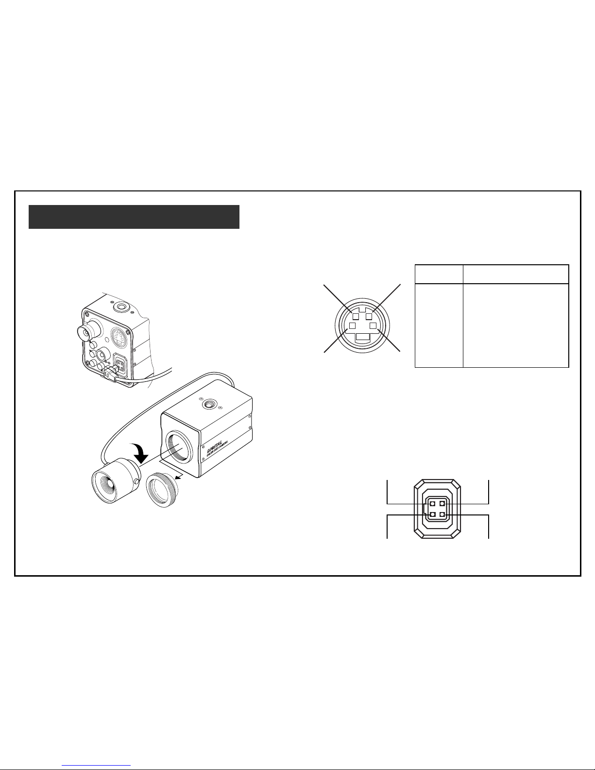
19
LENS INSTALLATION
P
W
R
L
E
N
S
S
-
V
ID
E
O
S
E
T
1
2
V
D
C
■ Please attach a lens cable when
using the Video type auto iris lens
When using the VIDEO type Auto- iris lens,
install the lens plug as follows.
If the plug on the cable is of a different type,
replace it with the provided 4-pin iris plug.
Pin assignment : S-Video connector (4-pin)
Video Camera Lens
43
21
+12V DC
N.C
Video Signal
GND
Pin No. Signal
1 GND
2 GND
3 Y (Luminance.
1Vp-p, 75Ω)
4 C (Chrominance,
0.286Vp-p, 75Ω)
Page 21

20
Mounting a lens
①
Remove the lens mount cap from the camera.
➁
Attach or remove the C-mount adapter depending on
the lens to be used.
Ø
If the adapter is attached so tightly that is difficult to
remove, use long-nosed pliers to remove it. Insert
the tips of the pliers into the holes with no threads,
thus turn to remove. Or a screwdriver can also be
used, as shown. Insert M3 screws into the holes so
that the screwdriver has something to grip. (Store
the C-mount adapter for possible future use.)
➂
Attach the lens to the lens mount. Secure it so that it
does not become loose.
➃
If the lens has an auto-iris mechanism, connect the
lens cable to the lens connector.
ADJUSTING AUTO-IRIS LENSES
Make this adjustment after connecting the camera
to a power source and a monitor.
1) Set AGC mode to off.
2) When using a Video type lens : Adjust the level
on the lens to produce minimum smear and
optimum pictures.
3) Set AGC mode to on. It is recommended that
the AGC be used in the “ON” mode after
adjusting the video level.
Page 22
21
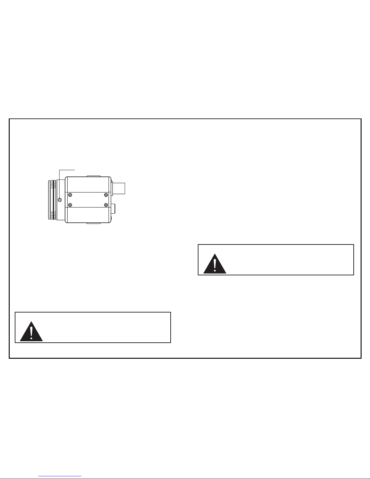
Back-focus adjustment
When a lens is mounted, adjustment of the back-focus may
sometimes be required. Adjust the lens focus ring when the
correct focus cannot be obtained.
WITH A FIXED-FOCUS LENS
1) Fully open the aperture and set the focus ring to "∞"
(infinity).
In the case of an auto-iris lens only, shoot a comparatively
dark object so that the aperture is fully open.
2) Loosen the two back-focus screw with a hex wrench,
and turn the lens mount to focus.
3) After adjusting the back-focus, tighten the backfocus
screw.
WITH A ZOOM LENS
1) Fully open the aperture and set the lens to the maximum
tele-photo position. Then turn the focus ring to focus.
In the case of an auto-iris lens only, shoot a comparatively dark object so that aperture is fully open.
2) Set the lens to its maximun wide-angle position.
3) Loosen the two back-focus screw with a hex wrench,
and turn the lens mount to focus.
4) After adjusting the back-focus, tighten the backfocus
screw.
5) Repeat step 1) ~ 3) until the difference between focusing
position 1) and 2) becomes smallest.
COLOR CCD CAMERA
DIGIT
DIGITALAL
Back-focus screw
Caution : Do not forcibly turn the back-focus
screw, as it will cause damage to the
camera.
Caution : Do not forcibly turn the back-focus
screw, as it will cause damage to the
camera.
Page 23

22
SPECIFICATIONS
Signal system IV-CCAM3 : NTSC
IV-CCAM3P : PAL
Pickup element Interline transfer 1/3” CCD
Effective plxels IV-CCAM3 : 768(H) x 494(V)
IV-CCAM3P : 752(H) x 582(V)
Scanning area 7.95(H) x 6.45(V)mm
Scanning system 2:1 interlace
Scanning frequency Hor. NTSC : 15.743kHz
PAL : 15.625kHz
Ver. NTSC : 59.94Hz
PAL : 50kHz
Sync system Internal
Video output
Composite video signal (1Vp-p, 75Ω, unbalanced)
Seperated Y/C signal (Y;1Vp-p/75Ω, C;0.286Vp-p/75Ω)
Video S/N ratlo 50dB (AGC OFF)
Hor, Resolution 470 TV lines
AGC range 0~34dB
Minimum illumination 0.8lux (F1.2, 50IRE)
Electronic shutter OFF/AUTO/MANUAL
Shutter speed range 1/60 (1/50 PAL), 1/100, 1/120,
1/250, 1/500, 1/1000, 1/2000,
1/4000, 1/10000, 1/30000,
1/50000, 1/100000 Second
White balance Selectable auto-tracking
(ATW), preset(AWC), and
MANUAL
White balance range 2,400K-10,000K
Backlight Compensation
ON/OFF selectable
(6-sensing zones)
Text display 24 alphanumeric characters
(ON/OFF selectable)
Special menu Gamma, Color adj.,Sharpness,
Contrast, Brightness,
Flickerless and Preset
GAMMA Variable
Flickerless ON/OFF selectable
Lens Mount C/CS mount
Camera mount 1/4 inch-2OUNC
(Top/ Bottom)
Page 24
23
SPECIFICATIONS
Power requirement DC11~DC13V
Power consumption 2.5 Watt
Operating temperature
-10°C to + 50°C
(14°F to 122°F)
Operating humidity less than 85% relative
Storage temperature -20°C to + 60°C
external dimensions 41(W) x 41(h) x 51.6(d)mm
1.6(W) x 1.6(h) x 2.1(d)inch
Weight 140g(0.31 lbs)
Lens connector plug
(E4-191J-100) 1
DC Jack Plug
(MP-121M) 1
Lens mount cap 1
C-mount adapter 1
Operation manual 1
Ø
The lens mount cap and C-mount adapter are attached
when supplied.
Notes :
If used continously, be sure to operate
less than 40°C for long term stable
performance.
Notes :
Ø Design and specifications are subject to change
without notice.
Ø
This color video camera is designed to output
video signals conforming to the NTSC (PAL)
standard, so that it cannot be used with video
recorder or color monitors which use color
systems other than NTSC (PAL) .
Page 25

 Loading...