

Page 1

Table of Contents
INTRODUCTION.........................................................................................................................................2
WARNING....................................................................................................................................................2
GENERAL DESCRIPTION........................................................................................................................3
UPERFLEX
S
IGISENSOR
D
PTIMIZER
O
UNCTIONS
F
ONTROLLER
4 C
............................................................................................................................. 3
..................................................................................................................................................... 4
....................................................................................................................................................... 5
...................................................................................................................................................... 5
INSTALLATION................................................................................................................... ....................... 6
OUNTING THE
M
YPICAL WIRING
T
ONTROLLER
SF4 C
.................................................................................................................. 6
............................................................................................................................................. 6
Joystick Controllers.................................................................................................................................... 7
Valves.......................................................................................................................................................... 8
Superflex 4 Controller.................................................................................................................................8
Power.......................................................................................................................................................... 9
Optimizer .................................................................................................................................................... 9
IRING (APPENDIX
W
5) ..................................................................................................................................... 9
OPERATION..............................................................................................................................................10
ENERAL
G
UNCTIONS FOR THIS APPLICATION (APPENDIX
F
PTIMIZER
O
....................................................................................................................................................... 10
1).......................................................................................... 10
..................................................................................................................................................... 10
Adjustments ............................................................................................................................................... 11
Diagnostic Menus..................................................................................................................................... 12
Customized Display (Appendix 2)............................................................................................................. 13
DJUSTMENTS AND CALIBRATION
A
................................................................................................................. 13
Active Adjustments.................................................................................................................................... 13
Bench / Static Adjustments........................................................................................................................ 16
Factory Default Values (Appendix 3)....................................................................................................... 16
TROUBLESHOOTING............................................................................................................................. 17
S ON SUPERFLEX
LED’
PTIMIZER DIAGNOSTICS
O
IGISENSOR
D
ONNECTORS
C
................................................................................................................................................... 19
................................................................................................................................................. 19
................................................................................................................................... 17
............................................................................................................................... 18
OPTIMIZER MENU FUNCTION DIAGRAM....................................................................................... 20
APPENDIX.................................................................................................................................................. 21
PPLICATION SPECIFIC FUNCTIONS
1. A
USTOMIZED OPTIMIZER DISPLAY
2. C
ACTORY DEFAULTS AND ADJUSTMENT LIMITS
3. F
NPUTS AND OUTPUTS CONNECTION TABLE
4. I
IRING DRAWING
5. W
file: SF4MAN.DOC -
..................................................................................................................................... 21
............................................................................................................ 21
............................................................................................................. 21
........................................................................................ 21
.............................................................................................. 21
1 -
December 30, 1996
Page 2

Introduction
The quality and versatility of your joystick control system can make a critical difference in the performance
of your machinery. That is why OEM Controls Inc. products are the controllers of choice for mobile
equipment manufacturers.
OEM, the largest manufacturer of controls for electrohydraulic valves, offers the industry’s most advanced
line of high-quality products. Their compact design, rugged performance, and expanded application
versatility can help improve the performance and capabilities of your equipment. Sophisticated electronic
control methods help create a responsive interface between the equipment and its operators.
For over 28 years, OEM has developed winning products by solving specific application challenges and
anticipating the ongoing needs of the industries we serve. We are prepared to help you meet your
performance requirements.
OEM configures each product to individual customer specifications, utilizing field-proven components, a
long list of options, and industry-leading engineering expertise. We can provide completely customengineered systems to most precisely match your configuration, control, and performance criteria, from
basic on/off functions to multi-axis joystick control.
Compatible with most electrohydraulic valves, OEM controllers feature heavy-duty construction in a
compact design. Metal internal structures and industrial-grade electronics are used to ensure long-term
reliability.
Warning
WARNING: IT IS THE PURCHASER'S RESPONSIBILITY TO DETERMINE T HE
SUITABILITY OF ANY OEM CONTROLS PRODUCT FOR AN INTENDED
APPLICATION, AND TO INSURE THAT IT IS INSTALLED AND GUARDED IN
ACCORDANCE WITH ALL FEDERAL, STATE, LOCAL AND PRIVATE SAFETY
AND HEALTH REGULATIONS, CODES AND STANDARDS.
Due to the unlimited variety of machines, vehicles and equipment on which our controls are used, and the
numerous standards which are frequently the subject of varying interpretation, it is impossible for OEM
Controls personnel to provide expert advice regarding the suitability of a given controller for a specific
application. The flexibility of our products allows us to offer thousands of custom configurations. We can
advise you of the various features that are available and you can examine models to see what meets your
needs. We believe our customers' engineering departments should be the qualified experts in their own
product field. If the product will be used in a safety critical application, the customer must undertake
appropriate testing to prevent injury to the ultimate user.
SHOULD YOU HAVE ANY QUESTIONS, OR IF ANY OF THIS WARNING IS UNCLEAR, PLEASE
CONTACT OEM CONTROLS, INC., 10 CONTROLS DRIVE, SHELTON, CT 06484 (203) 929-8431.
file: SF4MAN.DOC -
2 -
December 30, 1996
Page 3
General Description
The Superflex 4 System consists of joysticks and a stand alone controller that electrically drives
electrohydraulic valves. Typical applications include operating crane booms, fire truck ladders, track
driven machines and other hydraulic equipment with electrohydraulic valves and pumps.
Superflex 4 Controller
The Superflex 4 Controller is a rugged, micropro cessor controll ed device that can directly operat e four bidirectional electrohydraulic valves. The Superflex 4 receives inputs from Digisensors, switches, and other
transducers, and converts these signals into proportional PWM outputs to drive the valves. Each output
signal may be independently fine-tuned and calibrated by using the hand held Optimizer .
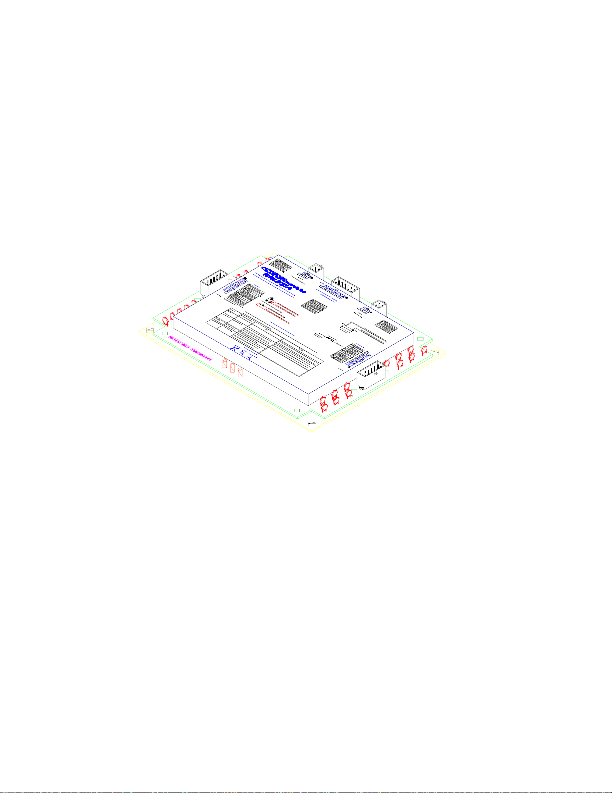
Figure 1
Figure 1 shows a Superflex 4 Controller. The Superflex 4 has three 12 pin connectors for inputs, outputs,
and power / Optimizer connections. (Revision B and later Superflexes also have two 4 pin connectors).
The connec tors are designa ted “BT1” to “BT5” throughout this manual. Three red LEDS p rovide the user
with status and diagnostic information. A user friendly label identifies the connectors and provides simple
troubleshooting information.
The Superflex 4 Controller is a versatile and flexible control device. It may be factory programmed by
OEM Controls Inc. to include many different options. A few examples of its flexibility include -
!"
The Superflex 4 is supplied with factory default settings for the electrohydraulic valves used. However, the
customer may select other default values and adjustment limits. This factory programmed data allows the
Superflex 4 to be installed and ready to use as delivered from the factory. Please contact OEM Controls
Inc. for details on customizing the Superflex 4 Controller for your particular application.
Single or dual coil valves with PWM frequencies from 33 to 1000 Hz.
"
Single or dual axis joysticks. Arotrack drive (convert dual axis to left and right track drive).
"
Discrete digital inputs for High / Low ranges, start up interlocks, ramp disable shutdown, etc.
"
Auxiliary outputs (2) for dump valves, alarms, multiplexed output selection, etc.
"
Various “belly” curves to modify the joystick controller’s characteristics.
file: SF4MAN.DOC -
3 -
December 30, 1996
Page 4
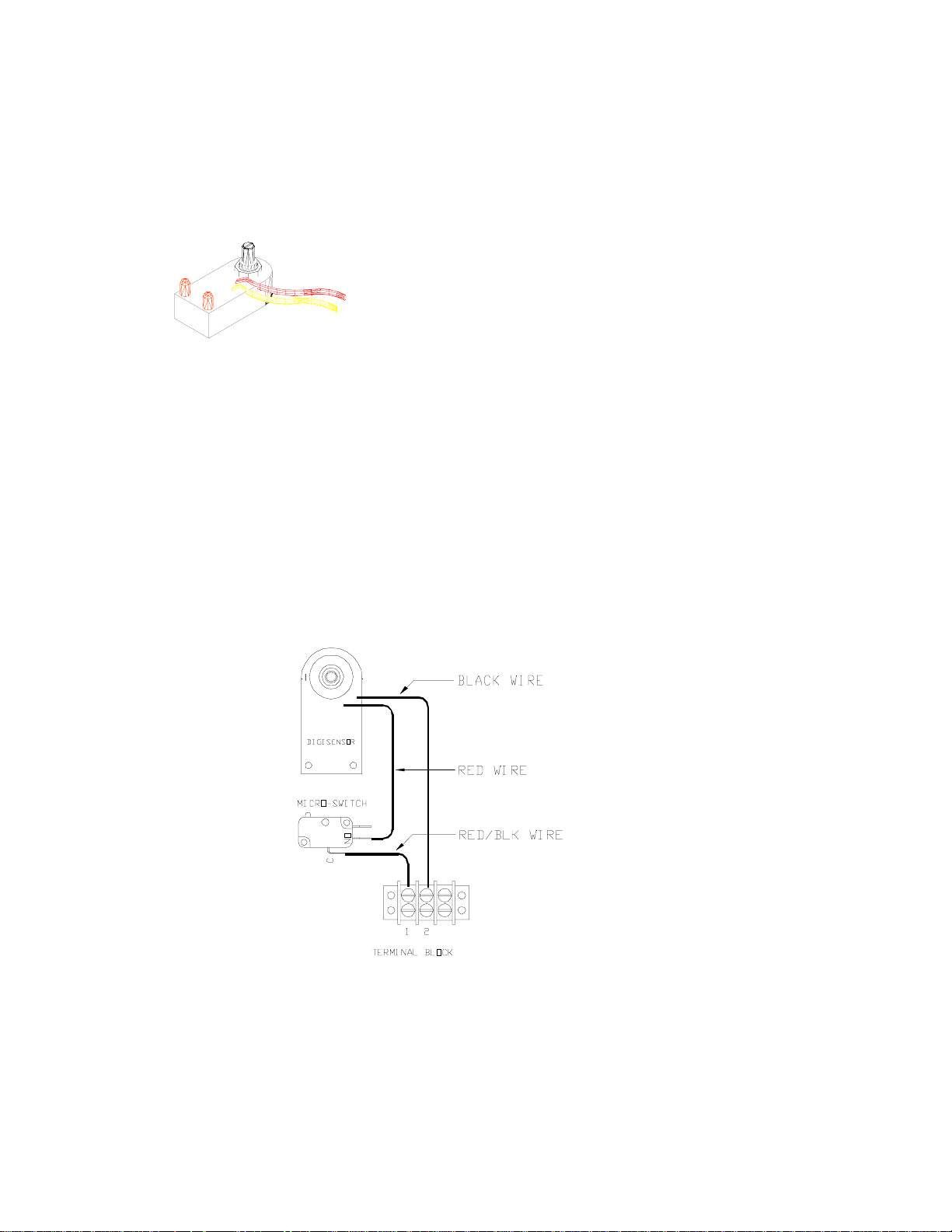
Digisensor
The Digisensor (Figure 2) is a small, rugged device that c onverts joystick handl e movement into an
electrical signal. The Digisensor requires only two wires, and can transmit its signal to a Superflex
controller up to 500 feet away. Figure 18 (on page 19) shows the various features of the Digisensor.
A potentiometer embedded in the Digisensor measures
the joystick controller’s movement (usually with a gear).
The potentiometer is also used for mounting the
Digisensor. Two red LEDS indicate the Digisensor
position (whenever power is applied). The “Direction
A” LED turns on when the potentiometer shaft is turned
counter-clockwise, and the “Direction B” LED turns on
when rotated clockwise. When the Digisensor’s shaft is
Figure 2
Two wires connect the Digisensor to the system. The red wire connects to the +12 or +24 volt power, and
the black wire connects to one of the Superflex inputs. Figure 3 shows typical wiring for a single axis
joystick controller. In this example, a microswitch turns on the Digisensor when the joystick handle is
moved from its center or “off” position.
centered (turned halfway between its ends) both LEDS
will be on. The section titled “Troubleshooting Digisensor” has additional details.
Figure 3
file: SF4MAN.DOC -
4 -
December 30, 1996
Page 5
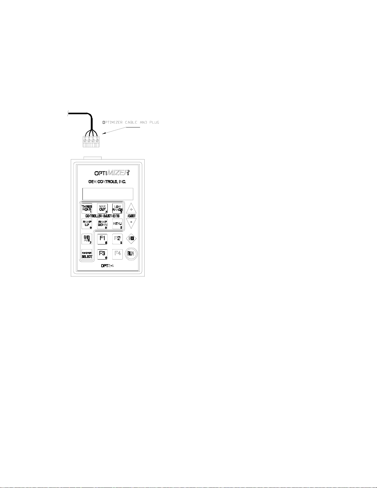
Optimizer
The OPT4 Optimizer is a hand held user interface with a keypad and an alphanumeric display. It is used as
a calibration and diagnostic tool, to display various system values, and to make adjustments to the Superflex
4 Controller.
Figure 4 shows the Optimizer and its connecting
cable. The Optimizer cable length should be
limited to 120 feet.
Figure 4
Functions
A typical system application uses four single axis, bi-directional joysticks as inputs and controls four bidirectional channels. Each channel has two proportional PWM (pulse width modulated) output signals, and
each signal has independently adjustable threshold, maximum output and ramp time adjustments. The AUX
output turns on whenever any of the joysticks are operated. Four digital inputs can be used to select high or
low range (dual speed option) for the 4 channels. Diagnostic indicator LEDS show the Superflex system’s
status and can be used for easy checkout. An Optimizer may be connected for calibration and
troubleshooting.
file: SF4MAN.DOC -
5 -
December 30, 1996
Page 6
Installation
Mounting the SF4 Controller
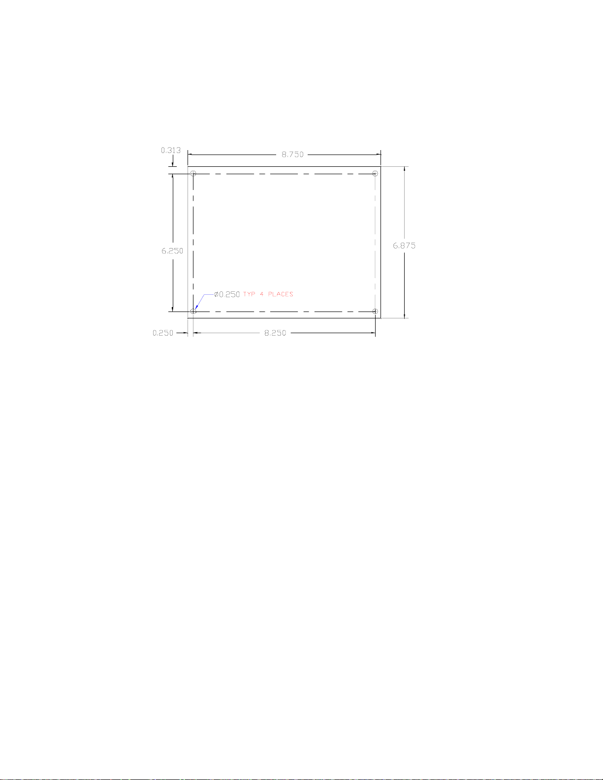
Figure 5
The Superflex Controller is an electronic circuit board assembly mounted on an aluminum plate. The
device can be mounted in standard enclosures or in another protected area. Mounting dimensions are
shown in figure 4. Allow at least 9 by 7 inches to mount the Superflex 4, and provide at least 3 inches of
clearance above it for the wire connectors and cable routing. (The Superflex 4 is approximately 1 inch in
height).
Since the Superflex 4 Control System is installed at the site of the machine’s final assembly there are many
installation variations. Follow these guidelines when installing or replacing the Controller -
"
Place the Superflex 4 in a metal enclosure, protected from rain and other fluids.
"
Be sure there are weep holes or one way drains at the bottom of the enclosure.
"
Use a minimum of 18 AWG wiring, especially on the power and output connections.
"
Install the wiring per SAE Specification J-1121.
"
Use 3 amp flyback diodes on all relay coils and non-proportional solenoid valves to prevent
EMI. Refer to the wiring drawing in appendix 5.
"
CAUTION
connectors from the Superflex 4 before welding to prevent damage to the system or to its wiring.
- Provide external current paths when welding on the machine. Disconnect all of the
Typical Wiring
Inputs and outputs are controlled by the particular application’s software program that is built into the
Superflex 4. The function of various terminals are dependent on the application. The following sections
provide general guidelines for wiring the system.
file: SF4MAN.DOC -
6 -
December 30, 1996
Page 7

Joystick Controllers
Figures 6 and 7 show typical single and dual axis joystick controllers with Digisensors. Typically, the
Digisensors are pre-wired to terminal blocks on the joystick. (Refer to instructions that come with your
custom joystick co ntroller for p roper mounting and gr ounding proced ures).
Figure 7
There are six inputs on the Superflex 4 Controller that may be connected to Digisensors mounted on
joystick controllers. (Usually, only the first four inputs are used). Figure 8 shows the wiring of a typical
single axis joystick. This device is connected to the Superflex 4 as follows -
"
Terminal 1 is connected to power (the +12 volt battery).
"
Terminal 2 is connected to one of the Digisensor inputs on the Superflex connector BT2.
The joystick controller may be located up to 500 feet from the Superflex 4 Controller.
Figure 6
Figure 8
file: SF4MAN.DOC -
7 -
December 30, 1996
Page 8

Valves
There are eight high current outputs on the Superflex 4 designed to drive four dual coil (bi-directional)
valves. Each output is rated at 3 amps maximum, and has built in short circuit protection. Figure 9 depicts
a typical connection. This example shows the channel 1 valve’s two coils connected to BT3 terminals 12
and 6 for the “A” and “B” directions. In general -
"
An output from Superflex connector BT3 is connected to the plus side of the valve.
"
The minus side of the valve is connected to the machines ground or battery minus terminal.
Figure 9
There are two AUX (auxiliary) high current outputs on BT3. Depending on the Superflex 4 application,
these outputs may control the machine’s dump valve, throttle, etc. The AUX outputs are connected in a
similar fashion as the valves shown above.
Superflex 4 Controller
The Superflex 4 has three 12 pin connectors: BT2 is used for inputs, BT3 for outputs and BT1 for power
and Optimizer connections (see figure 10 on the next page for the connector locations). Cables and / or
wiring harnesses may be purchased from OEM Controls in any desired length. Appendix 4 shows the
terminal pin number s and wiring for your par ticular application. The BT pin numbers are idendified in
figure 11 on t he next page.
Revision B and later Superflex 4 Controllers have two additional 4 pin connectors, BT4 and BT5.
Connector BT5 has power and ground connections, and BT4 has Optimizer connections. Either BT1, or
both BT4 and BT5 may be used for your application.
A label on the Superflex 4 Controller also identifies all connector pins and their functions.
file: SF4MAN.DOC -
8 -
December 30, 1996
Page 9

Power
Figure 10
The Superflex System requires a DC
voltage of 10 to 16 volts to operate
properly. This range covers machines
with a nominal 12 volt power source.
Figure 12 shows how connector BT1
connects to power and ground. Be
sure the power wire is of sufficient
size to provide current to the
Superflex and to all of the external
valves connected to the system. The
total system current is not to exceed
12 amps, including all active outputs.
Optimizer
Figure 12 also shows the wiring between Superflex connector BT1
and the Optimizer.
Wiring (Appendix 5)
A wiring diagram, included in appendix 5, gives additional
information on hooking up the input and output signals for your
specific application. Also refer to appendix 4 for the signal names
and BT pin numbers.
Figure 12
Figure 11
file: SF4MAN.DOC -
9 -
December 30, 1996
Page 10

Operation
This section only describes basic operation of the Superflex 4 System. Refer to the machine manufacturer’s
instructions for additional information on operating your equipment.
General
The Superflex 4 System essentially converts joystick handle movement into an electrical output signal to
drive the electro-hydraulic valve. The output signal increases proportionally to the amount of joystick
movement.
The dual range digital (switched) input provides two independently adjustable output ranges. The low
range is an adjustable percentage of the maximum output.
In a typical application, the AUX1 (auxiliary) output turns on whenever any of the eight valve outputs are
active.
Functions for this application (Appendix 1)
Refer to the information in appendix 1 for any additio nal features and functions that have been included in
your specific application. (This does not apply to the typical application described above).
Optimizer
Figure 13 on the next page identifies the display and important keys. The key functions will be described
below. To use the Optimizer, plug its cable into the Superflex Controller.
The Optimizer display will look like this, assuming that no joysticks are
operated (and the Superflex outputs are off).
When a joystick is operated, the Optimizer display will change to this. The
upper right portion identifies the active channel or function, and the lower
right portion indicates the actual output value. In this example, function 1
direction B (Fn1B) is active, with an output PWM duty cycle of 72.5%. This channel has been customized
to read “Rotate Left”. As the joystick is moved, the displayed value will change. If more than one joystick
is operated at the same time, so that several outputs are active, the Optimizer display will show the channel
who’s joystick was most recently moved.
There are five adjustment select keys - Threshold, Maxout, Low Range, Ramp Up and Ramp Down. These
keys are used to select one of these 5 parameters to adjust.
The Direction Select key toggles (alternates between) the A and B direction. This key only functions when
all joystick controllers are off. The Optimizer automatically selects the direction when a joystick is
operated; this makes active adjustments easy to perform.
The Function Select chooses one of the 4 channels for adjusting. This key only operates when all
controllers are off. Each time this key is pressed, the next function (or channel) is selected, that is 1 ... 2 ...
3 ... 4 ... 1 ... etc. The Optimizer automatically selects the function (channel) whenever a joystick is
operated, making active adjustments easy to perform.
RUN MODE, NORMAL
FUNCTIONS OFF
RUN: ROTATE L
Fn1B 72.5 %
file: SF4MAN.DOC -
10 -
December 30, 1996
Page 11

Figure 13
Figure 14 identifies various items that are displayed
when you are making an adjustment. The “value” is
flashing (blinking on and off) and will change as the
Plus or Minus keys are pressed. The Channel
(Function) and Direction are displayed generica lly on
the bottom line, and as the actual machine’s functions
on the top line. The parameter being adjusted (in this
example threshold) is shown at the upper left.
CAUTION -
Be sure to press the RUN key after
making an adjustment or the new setting will be lost
Figure 14
The Menu key accesses
less frequently used items,
other information and
diagnostics. A “three key
menu” system allows
additional functions and
features to be easily added
to SF4 while still having a
universal Optimizer. The
Enter key is used to step
through the various menu
items. The section
“Diagnostic Menus” below
describes the Menu and
Enter key functions.
The Plus and Minus keys
are used for changing the
various adjustments
(threshold, ramp, etc.).
The process is described
below. The Run key must
be pressed after making an
adjustment so the new
value is saved.
Adjustments
Threshold is the amount of output that causes the machine to just start to move or operate. The Threshold
value represents a PWM percent duty cycle, which corresponds to the initial voltage signal driving the valve
when the Joystick handle is moved slightly from its off position.
Max Out
desired speed. The Max Out value also represents a percent duty cycle, corresponding to the voltage signal
driving the valve when the Joystick handle is fully deflected (and high range is selected).
Low Range
ange setting rep resents a percent age of the Maximum Output value.
file: SF4MAN.DOC -
or maximum output is the amount of output that causes the machine to operate at maximum
sets the limited amount of output signal when the Joystick handle is fully deflected. The Low
11 -
December 30, 1996
Page 12

Threshold, Max Out and Low Range adjustments are made in 0.5 % steps.
Ramp Up
adjustment is made in te nt hs of a second.
Ramp Down
Ramp Down adjustments are also in tenths of a second.
sets the time the machine’s function will take to increase (accelerate) from off to full on. This
sets the time required for the machine’s function to decrease (decelerate) from full on to off.
Diagnostic Menus
Various pieces of information are available in the Diagnostic Menu mode.
This mode is started by pressing the “Menu” key. The Optimizer displays the
first menu item. Press the Enter key to step through all of the menu items.
The first four menu items display fixed data. Two examples are shown at the right.
The valve PWM frequency for the first two outputs (channels 1 and 2) is
followed by the valve frequency for the second two outputs (cha nnels 3 and
4). Next the OEM part number and serial number are shown.
The next three menu items are active displays
showing input and output signals. These
screens are useful for troubleshooting. The
switched digital inputs (see figure15) can be
tested on this display. If an input is On, the
display is a “1” and if it is Off or 0 volts, the
display is a “0”. Likewise the AUX outputs
and Digisensor inputs can be displayed. The
Troubleshooting guide has additional
information.
Figure 15
The next menu item is “Restore Factory Defaults” and is used to reset all of
the adjustable parameters to the settings that were programmed in by the
factory. The display looks like this, with the bottom line flashing. Pressing
the Plus key will restore the default values. Pressing the Enter key will step
to the next menu item.
The final three menu selections go together. They provide an alternate method of choosing adjustments,
channels and the direction for making changes. At each of these screens, the selected item (e.g.: TH, MX,
RU, RD or LR) will flash. Use the Plus key to select and the Enter key to go to the next menu. After
proceeding through these 3 menus, you will be able to adjust the selected variable.
FREQUENCY 1 2
100 Hz
OEM PART NUMBER
SF4-4-200.001x
RESTORE DEFAULT?
Yes=+ No=Enter
CONTROL ADJUST
TH MX RU RD LR
file: SF4MAN.DOC -
FUNCTION SELECT
Fn1 Fn2 Fn3 Fn4
12 -
DIRECTION
DIR A DIR B
December 30, 1996
Page 13

Customized Display (Appendix 2)
Your particular Superflex 4 System application may be customized to easily identify the machine’s
function. Nine characters may be specified for each function, channel and direction. For example - you
might choose “DRIVE FWD” for the machines drive forward, “BOOM LIFT” and “ROTATE R” for
boom functions, etc. Refer to the customized data located in Appendix 2 of this manual.
Adjustments and Calibration
Two different methods may be used to calibrate the system: 1) Active or 2) Bench / Static. In the Active
mode, the equipment is actually operated with the joystick controllers while making the adjustments. The
Bench / Static mode does not requir e operating the equipment or moving the joystick handles. For best
results, the Active method is recommended.
NOTE
- After making an adjustment, always press the RUN key
not pressed, the new settings will be lost as soo n a s the Optimizer is unplugged or the Superflex 4 power is
turned off.
to save the new value. If the RUN key is
Active Adjustments
WARNING
locate the machine in an area which is suitable for safe operation.
NOTE
operated. Plug in the Optimizer and turn on power. Follow any additional procedures specified by the
equipment manufacturer.
"
"
- The Action (Channel) and the Direction are automatically selected when a Joystick controller is
To adjust THRESHOLD (initial starting or creep speed) -
Move the jo ystick handle (of the function to adjust) just far enough so that the Optimizer display
changes from “Run Mode Functions Off” to “RUN: ... Fn...” At this point, the channel is
operating. Continue to hold the joystick handle in this position and perform the following steps.
Press the Threshold key. The Threshold value is displayed, and it blinks (flashes) to indicate that
it can be adjusted.
Press the Plus key to start or speed up this function if it does not move. OR Press the Minus key
to stop or slow down the function if it moves too fast.
Press the RUN key to sa ve the new value.
Repeat these steps for adjusting the Threshold in the opposite direction.
To adjust MAXOUT (full speed) -
If the machine has two speeds (Dual Range), make sure the High range is selected. (If this is not
possible, then temporarily adjust the Low Range to 100%.
Move the joystick handle fully on (to the end of its travel) in the direction to be adjusted, and hold
it there. Allow time for the machine function to accelerate to full speed.
Press the Maxout key. The Maximum Output value is displayed and flashes.
- Your machine will be operated during this calibration procedure. Be sure to
file: SF4MAN.DOC -
13 -
December 30, 1996
Page 14

Press the Plus key to increase the function speed. OR Press the Minus key to decrease the
function speed .
Press the RUN key to sa ve the new value.
Repeat these steps for adjusting Maxout in the opposite direction.
"
To adjust LOW RANGE (a slower speed range) -
NOTE - the Maxout adjustment should be made first. The Low Range speed is affected by the
Maxout setting; low range is actually a per centage of the maximum output.
Select the “low range” machine function. This may be a selector switch or other device.
Move the joystick handle fully on (to the end of its travel) in the direction to be adjusted, and hold
it there. Allow time for the machine function to accelerate to full speed.
Press the Low Range key. The Low Range value is displayed, and will be flashing.
Press the Plus key to increase the function speed. OR Press the Minus key to decrease the
function speed .
Press the RUN key to sa ve the new value.
Repeat these steps for adjusting Low Range in the opposite direction.
"
To adjust RAMP UP (acceleration time) -
Ramp Up determines the time it will take for the machine function to accelerate from off to full on
when the joystick handle is moved abruptly. Ramp up time is used to prevent sudden jerky
movements of the machine. Ramp up (and ramp down) time is adjustable in tenths of a second
increments.
If the machine has two speeds (Dual Range), make sure the High range is selected. (If this is not
possible, then temporarily adjust the Low Range to 100%.
Press the Ramp Up key. The Ramp Up value is displayed and flashing.
Move the joystick handle very quickly to its fully on position (to the end of its travel) in the
direction to be adjusted. Observe the machine’s response.
If the machine starts too quickly and/or is jerky, press the Plus key to increase the ramp up time.
OR If the machine takes too long to start up, press the Minus key to decrease the ramp up time.
Press the RUN key to sa ve the new value.
Repeat these steps for adjusting the Ramp Up time in the opposite direction.
"
To adjust RAMP DOWN (deceleration time) -
file: SF4MAN.DOC -
14 -
December 30, 1996
Page 15

Ramp Down determines the time it will take for the machine function to decelerate from full on to
off when the joystick handle is moved abruptly. Ramp down time is used to prevent sudden jerky
movements of the machine and allow smooth stopping.
CAUTION
function to stop.
If the machine has two speeds (Dual Range), make sure the High range is selected. (If this is not
possible, then temporarily adjust the Low Range to 100%.
Press the Ramp Down key. The Ramp Down value is displayed and will flash.
Move the joystick handle fully on in the direction to be adjusted. Allow the machine to reach full
speed. Then quickly move the joystick handle to its off position. Observe the machine’s
response.
If the machine slows down too quickly and/or is jerky, press the Plus key to increase the ramp
down time.
OR If the machine takes too long to stop, press the Minus key to decrease the ramp down time.
Press the RUN key to sa ve the new value.
Repeat these steps for adjusting the Ramp Down time in the opposite direction.
After all adjustments have been made for the desired machine performance, it would be helpful to record all
of these settings for future reference. The following table can be used to record the settings.
Threshold
Maxout
Low Range
Ramp up
Ramp down
- Setting the Ramp Down time too high will increase the time it takes for the machine
1A 1B 2A 2B 3A 3B 4A 4B
file: SF4MAN.DOC -
15 -
December 30, 1996
Page 16

Bench / Static Adjustments
Any adjustment can be made without operating the machine. This process is known as “static” or “on the
bench” calibration. Use the following steps -
Provide power to the Superflex 4 Controller. Connect the Optimizer.
Select a “function” (channel) by pressing the Function Select key one or more times, until the
desired channel (1 through 4) is d isplayed.
Select a direction (A or B) by pressing the DIR A/B key.
Select a contr oller adjustment by pressing one of Thresho ld, Maxout, Low Range, Ramp Up or
Ramp Down keys.
Use the Plus and Minus keys to make the adjustment.
Press RUN to sa ve the changes before powering down or disconne cting the Optimizer.
Factory Default Values (Appendix 3)
All defaults (preset values) as well as upper and lower limits to each adjustment range may be specified by
the customer. These setting are installed by OEM Controls when your Superflex 4 Controller is
manufactured. After making adjustments with the Optimizer, it may be desirable to return to these default
values. This task is easily accomplished with the Optimizer.
Apply power to the Superflex 4 Controller and connect the Optimizer.
Press the Menu key. Then press the Enter key several times, until the Optimizer displays “Restore
Defaults?”.
Press the Plus key to restore the default values. The Optimizer displays “BUSY” while the
original values are copied. This may take several seconds, depending on how many values need to
be restored. Then the Optimizer will momentarily display “DONE” and return to the default run
screen. Be sure to wait
to the Superflex 4 Controller.
for this to happen before disconnecting the Optimizer or turning off power
file: SF4MAN.DOC -
16 -
December 30, 1996
Page 17

Troubleshooting
The Superflex 4 System has been designed to perform in the harsh environments of the mobile equipment
industry. Most of the common problems encountered are external to the Superflex 4 Controller. Problems
may include: broken wires, loose or corroded or defective connections, wiring errors, wiring shorts, and
improper power supply voltages. The Superflex 4 Controller has several built in features that can assist
with testing and troubleshooting your system.
Check for the following machine related problems -
LED’s on Superflex
Figure 16 shows the location of three red indicator LEDS. These indicators provide the following
information.
"
Power is turned on and supplied to the Superflex. Supply voltage is OK (batteries aren’t weak).
"
Make sure all cables and wiring are connected properly.
"
Be sure the ground wiring is good.
"
Are there any machine interlocks (or “enable” signals) that are preventing operation?
Figure 16
"
The middle or CPU LED flashes if system is OK. This LED is off if there is no power being supplied to
the Superflex. If this LED is on constantly (not flashing) there is a CPU failure, and the Superflex 4
Controller must be replaced or repaired by OEM Controls, Inc.
"
The INPUT LED flashes whenever one or more joysticks (Digisensors) are operated. This LED is off if
all microswitches (Digisensors) are off. If this LED remains off when a joystick is operated, check the
wiring, and make sure there is power to the joystick. This LED will be on continuously (not flashing) if one
of the Digisensor wires is shorted to +12 volts.
file: SF4MAN.DOC -
17 -
December 30, 1996
Page 18

"
The OUTPUT LED flashes when any of the PWM outputs are active. It will turn off when all of the
outputs are off (this may take several seconds if a long Ramp Down time is used). If the output LED is on
continuously (not flashing) then one of the 8 PWM outputs is shorted to ground. Operate one joystick at a
time while observing this LED to determine the output. Then check the wiring and correct the short circuit.
Optimizer Diagnostics
The Optimizer can be used for system testing and troubleshooting. When the
Optimizer is plugged into the Superflex, it will start by displa ying the “RUN”
screen. If the display is blank, then check the power and ground wires to the
Optimizer. If the display looks like the example shown here, there is a
communication problem between the Superflex 4 Controller and
the Optimizer. This is most likely a connector or wiring problem.
Digisensor operation may be checked by using one of the diagnostic menu displays. Press the Optimizer’s
MENU key, and then press the ENTER key several times, until the display’s top line reads “DS1 DS2 DS3
DS4”. Below each of these indicators is the actual data being sent by a particular Digisensor. By moving
the joystick handle, the data will change.
The displayed Digisensor data will decrease to 0 when the joystick is moved in the “A” direction
(Digisensor potentiometer shaft rotates counterclockwise). Likewise, the displayed data will increase to
511 when the joystick handle is moved in the “B” direction (Digisensor shaft rotates clockwise). When the
joystick is centered, the Optimizer’s data will be approximately 255.
Four digital inputs can be tested (see figure17).
Press the Optimizer’s MENU key and then press
the ENTER key several times to reach this menu
item. Then observe the Optimizer display while
operating the machine controls that correspond to
these inputs. A “1” is displayed when the input is
at a high voltage ( at least 10 volts ) or “on”. A
“0” is displayed when the input is at ground or
“off”.
INITIALIZING
SYSTEM
Figure 17
file: SF4MAN.DOC -
18 -
December 30, 1996
Page 19

Digisensor
There are two LEDS on a Digisensor. To check for proper operation, apply power to the Digisensor and
observe these LEDS. See Figure 18.
Power may be supplied by the machine or by using a fresh 9 Volt transistor radio battery. Connect the
battery plus to the red wire, and the battery minus to the black wire. One or both LEDS should be on. If
neither LED turns on, replace the Digisensor.
Next, rotate the Digisensor’s potentiometer shaft.
When it is turned fully counter-clockwise, the left
“direction A” LED turns on. When the shaft is turned
fully clockwise, the right “direction B” LED turns on.
There is a small area when the potentiometer shaft is
turned about halfway where both LEDS are on. This is
important for aligning the Digisensor to the Joystick
controller.
Whenever a Digisensor is mounted to a joystick
controller, the mechanical alignment must be checked
and adjusted if necessary. This is important as the
Superflex 4 Controller depends on proper Digisensor
signals to operate the valves. Check the Digisensor
LEDS when the Joystick handle is in its center or “off”
position. NOTE - it may be necessary to operate the
joystick’s on/off micro-switch to apply power to the
Digisensor. Both LEDS must be ON when the handle
Figure 18
is centered. If this is not the case, rotate the shaft until
both LEDS turn on, and then tighten all mechanical
hardware.
Connectors
Replacement connectors are available from OEM Controls, Inc. or the connector manufacturer.
Superflex 4 Controller connectors BT1, BT2 and BT3 -
OEM part number EPCN/932 (body) and EPWT/835 (pins, also for BT5)
AMP Inc. 770581-1 (body) and 171637-1 (pins, also for BT5)
Superflex 4 Controller connectors BT4 and BT5 -
OEM part number EPCN/938 (body) and EPWT/839 (gold pins for BT4 only)
AMP Inc. 172167-1 (body) and 171637-3 (gold pins for BT4 only)
Optimizer Connector
OEM part number EPCN/859
Curtis Industries, Inc. PA256/5.08/4
file: SF4MAN.DOC -
19 -
December 30, 1996
 Loading...