

Page 1
CANBus Product Line
USERS MANUAL
OEM Controls Inc.
SUMMER 2006
10 Controls Drive, Shelton CT 06484
203.929.8431
www.oemcontrols.com
Page 2

OM-17288
TABLE OF CONTENTS
1.0 GENERAL INFORMATION ....................................................................................................... 3
3.0 MECHANICAL INSTALLATION ................................................................................................ 6
4.0 ELECTRICAL INSTALLATION ................................................................................................. 8
5.0 CANBUS MODULE PLACEMENT/SYSTEM WIRING ............................................................ 10
6.0 IDENTIFICATION KEY ............................................................................................................ 13
7.0 HUMAN MACHINE INTERFACE ( HMI ) ................................................................................. 14
8.0 CANBUS LED OPERATION ................................................................................................... 20
9.0 DOWNLOADING APPLICATION SOFTWARE WITH TDL ..................................................... 22
10.0 SPECIFICATIONS ................................................................................................................... 33
11.0 DOCUMENT REVISION HISTORY.......................................................................................... 37
CANBus USERS MANUAL Page 2 of 38
Revision C
GJO*07-12-06 ORIGINAL
Page 3

1.0 GENERAL INFORMATION
1.1 OEM Controls, the industry leader of electro-mechanical joystick controls and electronic
control systems introduces its family of CAN Bus multiplexing electronic control modules.
Utilizing over 20 years of experience in the design and manufacturing of microprocessorbased electronic systems as well as listening to the "wish lists" of our customers, OEM
Controls has developed the state-of-the-art, environmentally hardened and economical
solution for electronic control in the mobile equipment industry. The CANbus line of
products offers the highest level of quality and functionality in the industry today with;
-On-machine adjustability and troubleshooting– no external device or computer needed.
-Short-circuit, over-voltage and reverse-polarity protection.
-Compact and economical–modules spread out to where they are needed Instead of
running more cable.
-Versatile– factory programmable I/O designation (input vs. output, sink vs. source).
-4 channel current regulation on one module.
-High output resolution for precise function control.
1.2 This document will serve the User of this equipment as a Manual of Operations, thereby
allowing the proper installation and use of the CANBus system that has been designed for
the application at hand. The information covered will be generic in nature so as to define
the standardly available hardware. Documentation for the application specific functionality
of this control system can be obtained by contacting the manufacturer of this equipment.
OM-17288
CANBus USERS MANUAL Page 3 of 38
Revision C
GJO*07-12-06 ORIGINAL
Page 4

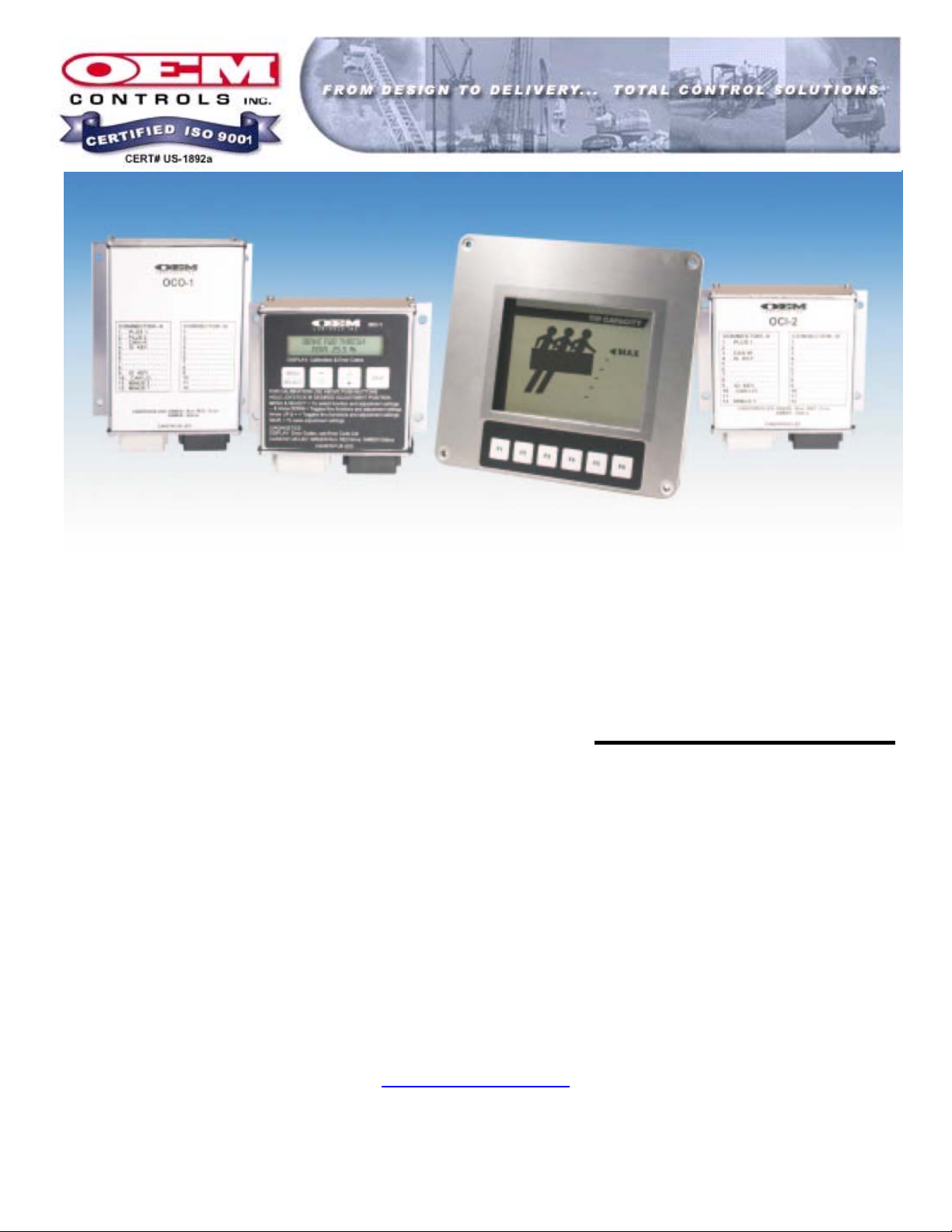
2.0 CANBus SYSTEM COMPONENTS
2.1 Input Modules
2.1.1 OCI-1 : Master Input Module
2.1.1.1 The OCI-1 is the core of the OEM CANBus control system. It is the
module that serves as the home for the application software that
determines how each module interacts with the machine it is installed
on. The OCI-1 also allows the operator to make active adjustments as
well as monitor the operation of the entire control system through use
of the LCD information panel and membrane keypad.
2.1.2 OCI-2 : Slave Input Module
2.1.2.1 The OCI-2 is a secondary or “slave” module for the OEM CANBus
control system. The primary purpose for the OCI-2 is remote, analog
and/or digital, inputs with a few low current outputs. .
2.1.3 OCI-3 : Multi Axis Joystick Input Module
2.1.3.1 The OCI-3 is a secondary or “slave” module for the OEM CANBus
control system. The primary purpose for the OCI-3 is remote, analog
and/or digital, inputs with a few low current outputs. It is designed to
mount directly to the JS8 family of joystick products but can be
mounted and utilized separately.
2.1.4 OCI-4 : Single Axis Controller Input Module
2.1.4.1 The OCI-4 is a secondary or “slave” module for the OEM CANBus
control system. The primary purpose for the OCI-4 is remote, analog
and/or digital, inputs. It is designed to mount directly to the MS7 type
joystick product.
2.2 Output Modules
2.2.1 OCO-1 : Standard Resolution PWM Output Module
2.2.1.1 The OCO-1 is a secondary or “slave” module for the OEM CANBus
control system. The primary purpose for the OCO-1 is remote, analog
and/or digital, outputs with few inputs. This module provides standard
PWM, up to 3 Amp, outputs.
2.2.2 OCO-2 : Hi Resolution / Current Source Output Module
2.2.2.1 The OCO-2 is a secondary or “slave” module for the OEM CANBus
control system. The primary purpose for the OCO-2 is remote, analog
and/or digital, outputs with few inputs. This module provides high
current and current regulated PWM, up to 5 Amp, outputs
OM-17288
CANBus USERS MANUAL Page 4 of 38
Revision C
GJO*07-12-06 ORIGINAL
Page 5

2.2.3 OCO-3 : Ratiometric ( Danfoss ) Output Module
2.3 Displays
2.3.1 OCD-2 : 320 x 240 Graphical User Interface
OM-17288
2.2.3.1 The OCO-3 is a secondary or “slave” module for the OEM CANBus
control system. The primary purpose for the OCO-3 is remote, analog
and/or digital, outputs with few inputs. This module provides
ratiometric PWM outputs
2.3.1.1 The OCD-2 is a secondary or “slave” module for the OEM CANBus
control system. This display module is monochrome with backlighting
and transflective screen for exceptional viewing in daylight. The
primary purpose for the OCD-2 is graphical display of machine
functions and operational information and has remote, analog and/or
digital, inputs with a few low current outputs
CANBus USERS MANUAL Page 5 of 38
Revision C
GJO*07-12-06 ORIGINAL
Page 6

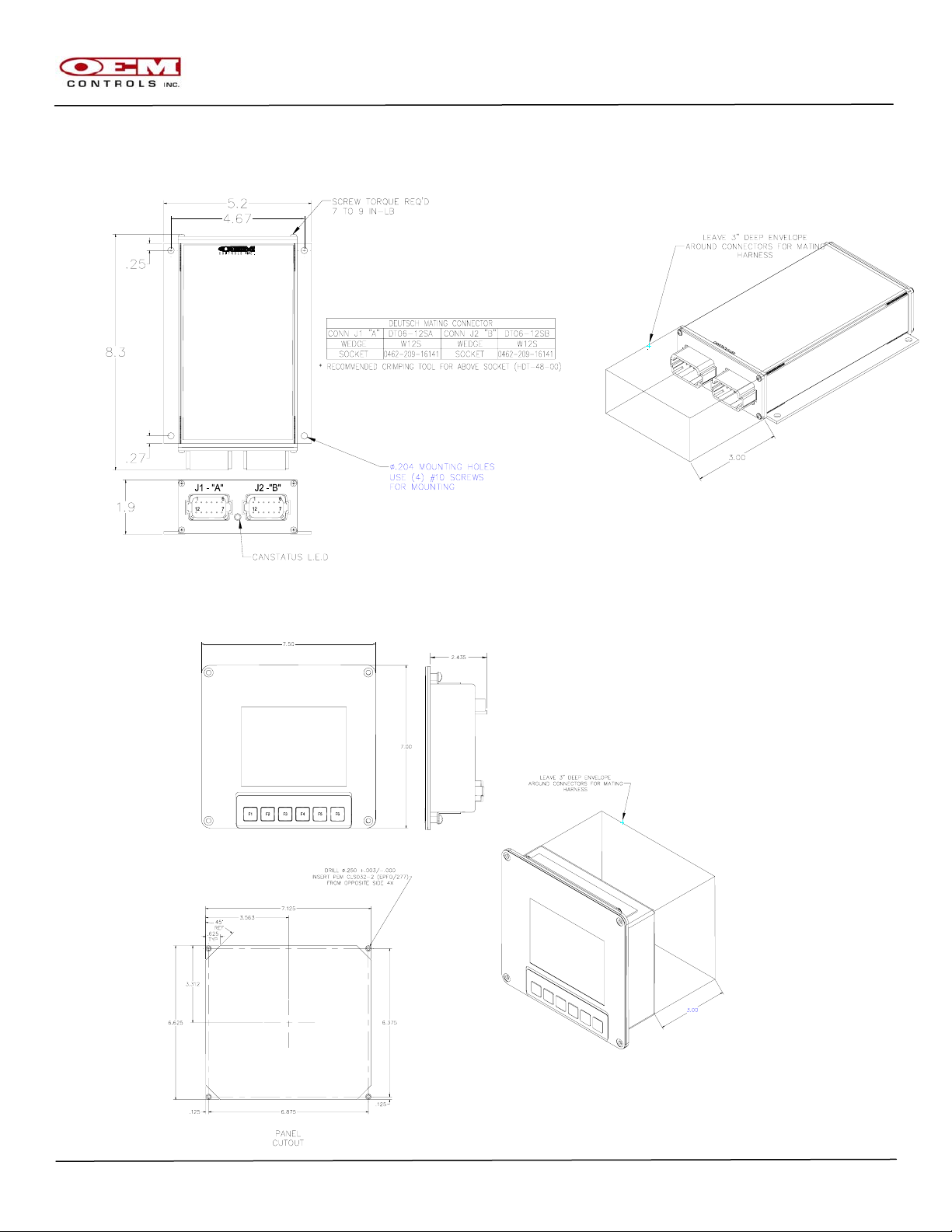
3.0 Mechanical Installation
3.1 OCI-1, OCI-2 ( and similar )
3.2 OCO-1 ( and similar )
OM-17288
CANBus USERS MANUAL Page 6 of 38
Revision C
GJO*07-12-06 ORIGINAL
Page 7
OM-17288
3.3 OCO-2 ( and similar )
3.4 OCD-2 ( and similar )
CANBus USERS MANUAL Page 7 of 38
Revision C
GJO*07-12-06 ORIGINAL
Page 8
Electrical Installation
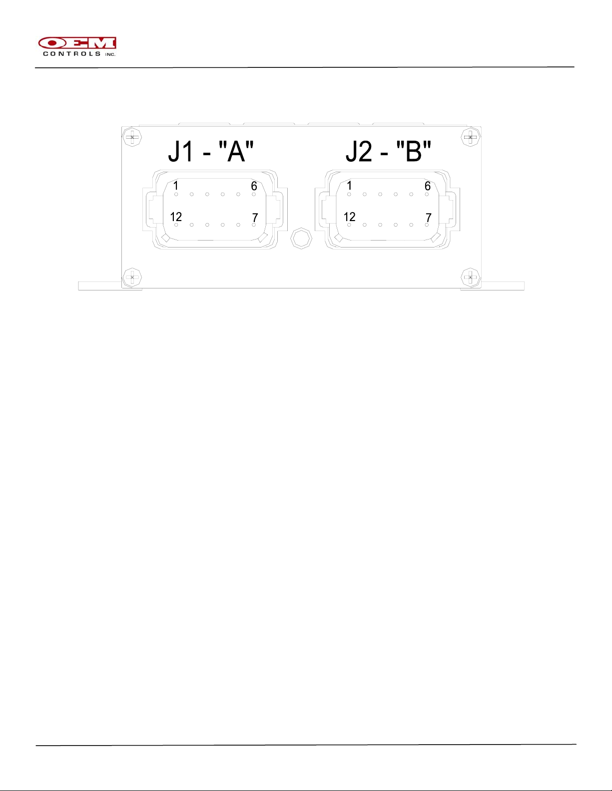
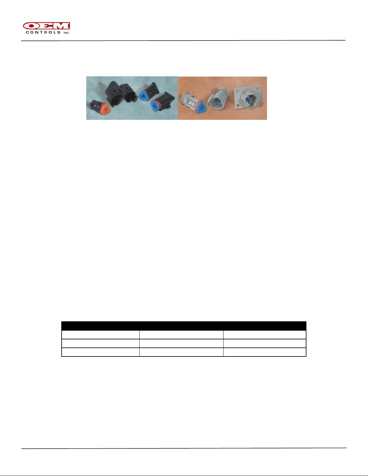
4.1 Connector Layout ( All Modules )
4.1.1 Connector Information ( Deutsch Part Numbers )
Connector “A” mates with
Connector “B” mates with
4.2 Power Supply
4.2.1 Typical Supply Voltage : 8-32 VDC
4.2.2 Protection: The OCI Modules are protected for the following adverse conditions
and can withstand these conditions without any permanent damage to the
module.
4.2.2.1 Reverse polarity: The VBat and Ground terminals can be swapped
4.2.2.2 Short Circuit: Any Input or Output from the Module can be shorted to
4.2.2.3 Over voltage: The module is able to withstand Transient Voltage
OM-17288
- Deutsch DT06-12SA ( Grey )
- W12S Wedge ( 1 pc )
- 0462-209-16141 Sockets ( up to 12 pieces )
- 114017 Seal Plug ( for unused connections )
- Deutsch DT06-12SB ( Black )
- W12S Wedge ( 1 pc )
- 0462-209-16141 Sockets ( up to 12 pieces )
- 114017 Seal Plug ( for unused connections )
without the possibility of permanent module damage.
VBat or Ground without the possibility of permanent module damage.
levels per IEC specification 61000-4-5:1995
CANBus USERS MANUAL Page 8 of 38
Revision C
GJO*07-12-06 ORIGINAL
Page 9

OM-17288
4.3 Standard Connections
4.4 Input-Output ( I-O ) Connections
4.4.1 The I-O configuration for your application is controlled by the Application
Software loaded into each CANBus module used in your system. Consult the I-O
sheet associated with your application for your specific connection. Contact
OEM Controls for the I-O Sheet that maps your application.
CANBus USERS MANUAL Page 9 of 38
Revision C
GJO*07-12-06 ORIGINAL
Page 10

5.0 CANBus Module Placement/System Wiring
Your CANBus system modules are all interconnected by means of Two Wires
- CANH (CAN High) and CANL (CAN Low) - plus the addition of a common shield wire. It is
Important to the operation of your CANBus system that the recommended module placement
and system wiring be followed very closely. Improperly placed/wired CANBus modules may
result in an inoperable system. It is important to carefully map out how you will route the
CANH and CANL signals from module to module so as not to compromise the signal
integrity because this information makes its way from one point to another on
your application.
Different Types of Modules
As received, the CANBus modules you have been supplied with
have been configured to be wired in a specific order based on your
application.
There are two types of modules your system could possibly use.
Full Termination : This is a CANBus module that has been
placed at the start or at the end of a BUS line
Stub Termination : This is a CANBus module that has been
placed in between the modules with full termination.
ENGINE
COMPARTMENT
FULL
TERMINATION
OPERATORS
CAB
STUB
TERMINATION
CURBSIDE
CONTROL
STUB
TERMINATION
START END
2 2 2
OM-17288
WINCH
STATION
FULL
TERMINATION
CANBus USERS MANUAL Page 10 of 38
Revision C
GJO*07-12-06 ORIGINAL
Page 11
OM-17288
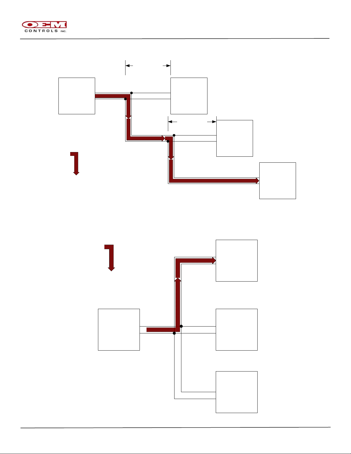
Correct Cable Wiring
ENGINE
COMPARTMENT
FULL
TERMINATION
1meter Max
OPERATORS
CAB
STUB
TERMINATION
START
1meter Max
CURBSIDE
CONTROL
STUB
TERMINATION
PRIMARY BUS PATH
WINCH
STATION
FULL
TERMINATION
END
Incorrect Cable Wiring
PRIMARY BUS PATH
WINCH
STATION
FULL
TERMINATION
END
ENGINE
COMPARTMENT
FULL
TERMINATION
OPERATORS
CAB
STUB
TERMINATION
START
CURBSIDE
CONTROL
STUB
TERMINATION
CANBus USERS MANUAL Page 11 of 38
Revision C
GJO*07-12-06 ORIGINAL
Page 12
J1939 “Y” Connectors
OEM recommends the use of Deutsch DT series connectors
manufactured for the specific purpose of CANBus communication.
OM-17288
J-1939/11 3-WIRE SYSTEM
Receptacle
DT04-3P-P007 Receptacle, “Y” Connector
DT04-3P-E008 Receptacle, Grey, w/Shrink Boot Adapter
DT04-3P-EE01 Receptacle, Black, w/Shrink Boot Adapter
Plug
DT06-3S-E008 Plug, Grey, w/Shrink Boot Adapter
DT06-3S-EP11 Plug, Black, w/Shrink Boot Adapter
DT06-3S-P032 Plug, Black, w/Shrink Tubing Adapter, Single Piece
Wedge Lock
W3P-1939 Wedge Lock, Blue
W3S Wedge Lock, Orange
W3S-P012 Wedge Lock, Green
W3S-1939 Wedge Lock, Blue
W3S-1939-P012 Wedge Lock, Blue
Pins/Sockets
0460-202-1631 Pin, Size 16, Gold
1060-16-0144 Pin, Size 16, Gold, Stamped & Formed
0460-247-1631 Pin, Size 16, Extended
0462-201-1631 Socket, Size 16, Gold
1062-16-0144 Socket, Size 16, Gold, Stamped & Formed
0462-221-1631 Socket, Size 16, Extended
CANBus Cable Assembly
OEM recommends running Twisted Shielded Pair cable between
Modules, wired to the J1939 3 pin connector as follows;
PIN FUNCTION WIRE COLOR
A CAN(H) YELLOW
B CAN(L) GRAY OR GREEN
C SHIELD BRAIDED STRAND
CANBus USERS MANUAL Page 12 of 38
Revision C
GJO*07-12-06 ORIGINAL
Page 13

6.0 Identification Key
Each module in the CANBus system is assigned a unique Node Identifier that is registered in
the Master module ( most commonly the OCI-1 ) to perform a specific function for the system
as a whole. The CANBus system relies on an external resistive identification key which is
connected to the mating connectors of all Modules in the system (except the Master Module,
which always has
a “00” identifier ) This will allow you to plug a new replacement module into the
same location and have the system operational without initializing the new
module.
Systems where multiple modules of the same type may be used (e.g.,more than
one OCI-2 ) must use a unique Identification Key for each module. For
example, the first OCI-2 may use IDK-00 and the second OCI-2 may
use IDK-01, but they are not allowed to both use the same ID Key.
Consult the I-O sheet associated with your application for your specific Identification Key
assignments. Contact OEM Controls for the I-O Sheet that maps your application.
OM-17288
CANBus USERS MANUAL Page 13 of 38
Revision C
GJO*07-12-06 ORIGINAL
Page 14

OM-17288
7.0 Human Machine Interface ( HMI )
The OCI-1 has an integrated multi segment , two line display with membrane keys that allow it to
be used as the main interface to system controls and adjustments. The Human Machine Interface
( referred to as the HMI ) will serve as your window into the application software to allow the
operator to monitor/adjust the following information;
- Active Function Being Used
- Part Number and Serial Number
- Restore the Factory Default Settings
- Output Calibrations ( Thresh,Max,Ramp.etc)
- I-O Status
- CANBus Status
CANBus USERS MANUAL Page 14 of 38
Revision C
GJO*07-12-06 ORIGINAL
Page 15

7.1 User Interface Keys
7.1.1
SELECT
MENU
7.1.1.1 <MENU> enters a new menu screen and/or
7.1.1.2 <SELECT>s the flashing item.
7.1.2
----
7.1.2.1 <MINUS> decreases an adjustable parameter such as ramp time.
7.1.2.2 <DOWN> selects the previous item in the current menu’s list.
7.1.3
+
7.1.3.1 <PLUS> increases an adjustable parameter.
7.1.3.2 <UP> selects the next item in the current menu’s list.
7.1.4
SAVE
7.1.4.1 <SAVE> saves the new data to EEPROM (permanent memory
storage).
Simultaneously pressing <UP> and <DOWN> will reset the HMI to menu screen 0.
+
----
OM-17288
CANBus USERS MANUAL Page 15 of 38
Revision C
GJO*07-12-06 ORIGINAL
Page 16

OM-17288
POR menu [ Menu Screen 0 ]
RUN MODE: NORMAL
FUNCTIONS OFF
RUN: DRIVE FWD
Fn1A 50.5 %
Part Number and Serial Number
PN: OCI1-103.000
SN: 000000001
Restore Factory Defaults
RESTORE DEFAULTS
PRESS SELECT
RESTORE DEFAULTS
“PRESS SELECT” is blinking.
The above three screens are in the MAIN menu. Use <UP> and <DOWN> to select one for viewing.
Press <MENU> to go to the following screen.
Top Level selection menu
ADJUST CAN BUS
IO TEST MAIN
CAN BUS
IO TEST MAIN
“ADJUST” is blinking
Use <UP> and <DOWN> to select one of the menu choices (which will be flashing) and then
press <MENU> to go there.
Press <EXIT> to return to menu screen 0.
CANBus USERS MANUAL Page 16 of 38
Revision C
GJO*07-12-06 ORIGINAL
Page 17

DRIVE FWD THRESH
Fn1A 25.5 %
[menu screen 10] “DRIVE FWD” is blinking
DRIVE FWD THRESH
Fn1A 25.5 %
[menu screen 11] “THRESH” is blinking
DRIVE FWD THRESH
Fn1A 25.5 %
[menu screen 12] “the adjustable parameter” is blinking
The HMI will enter menu screen 10 if all joystick channels are OFF (for static
adjust).
The HMI will enter menu screen 11 if one or more channels are ON, with the
most recently moved joystick’s function selected.
The HMI remembers the function (channel and direction) and the adjustment that
was most recently made for ease of use. On initially powering the OCI-1,
channel 1 direction A Threshold is selected.
Use <UP> and <DOWN> to select a flashing item. Use <SELECT> to select it
and go to the next menu screen. Use <SAVE> / <EXIT> to save an adjustment
and return to the previous menu screen.
OM-17288
JS Controller adjustment menus
THRESH
Fn1A 25.5 %
DRIVE FWD
Fn1A 25.5 %
DRIVE FWD THRESH
Fn1A %
Use <PLUS> and <MINUS> to adjust a parameter. Note – there are customer
specified limits to every adjustment
CANBus USERS MANUAL Page 17 of 38
Revision C
GJO*07-12-06 ORIGINAL
Page 18

I/O Test menus
AI 10 11 12 V
9.99 9.99 9.99
Di11 12 13 14 15
1 1 1 0 0
Do35 36 37 38 39
1 1 1 1 0
VDD POWER SUPPLY
12.34 Volts
PWM 11 PWM 12
45.5 % 100.0 %
These four screens are in the IO TEST menu. Pressing <MENU> will cycle
through them. When in a given screen, such as AI, use the <UP> and <DOWN>
keys to scroll through all of the system’s input or output signals.
Press <EXIT> to return to the top level menu screen.
CANBus menus
OCI-1 BRAIN
ID 0 OPERATING
OCO-1 MAIN BANK
ID 102 OPERATING
OCO-1 AUX BANK
ID 103 OPERATING
OCI-1 BUCKET JS
ID 64 NO DATA
There is one display screen for each CANopen module in the system.
The first line is a 16-character string (put in by the application engineer) that
identifies the product type and additional information.
The second line shows the CANopen Node ID and the bus status which is one of –
-OPERATING normal operation per CiA spec.
-STOPPED stopped per CiA spec
-PRE-OP pre-operational (just powered up) per CiA spec
-RESET just performed a power-on reset per CiA spec
-NO DATA the module is not communicating
OM-17288
CANBus USERS MANUAL Page 18 of 38
Revision C
GJO*07-12-06 ORIGINAL
Page 19

RESTORE DEFAULTS
PRESS SELECT
RESTORE DEFAULTS
YES or NO ?
Use the <UP> and <DOWN> keys to select YES if you wish to actually restore all
adjustments to their factory default settings. Then press <SELECT>
If “YES” was selected, you will see the following animated screen.
RESTORING NOW !
...
After this is finished, the HMI will return to menu screen 0.
OM-17288
Restore Factory Defaults
RESTORE DEFAULTS
“PRESS SELECT” is blinking.
RESTORE DEFAULTS
YES or NO ?
“NO” is blinking.
RESTORING NOW !
...........
CANBus USERS MANUAL Page 19 of 38
Revision C
GJO*07-12-06 ORIGINAL
Page 20

OM-17288
8.0 CANBus LED Operation ( Based on CiA 303 Specification )
Each OEM Controls CAN Module has a BI-Color status LED, usually located between the
Deutsch connectors. This LED provides easy verification that the CANopen bus is
OK, and also allows easy system troubleshooting by illuminating Red, Green, or Amber ( Red and
Green on at the same time ).
In many cases, the BI-color LED will indicate two bits of information. For example, if the GREEN
led is on continuously, but the RED led is doing a “double flash”, this means that the can module
is in the operational state, but that a node guard error has occurred.
INDICATION
OFF
BLINK
a continuous on/off
series, .2 sec ON
and .2 sec OFF
ON
SINGLE
FLASH
a .2 sec ON
followed by 1 sec
OFF
\DOUBLE
FLASH
.2 sec On,
.2 sec Off,
.2 sec On followed
by 1 sec Off
ALTERNATING
GREEN LED
FUNCTIONALITY
(RUN MODE ERRORS)
“NMT”
N/A
(BRIEFLY AT POWER UP } NO ERRORS N/A
PREOPERATIONAL STATE CONFIGURATION ERROR
OPERATIONAL STATE
"REDUCED BUS" ERROR
STOPPED STATE
N/A
GREEN AND RED -
REFERENCE ABOVE
RESULTS FOR EACH
COLOR
RED LED
FUNCTIONALITY
(BUS ERRORS)
"BUS OFF" ERROR
CAUSED BY >255
MESSAGE ERRORS
CAUSED BY >96
MESSAGE ERRORS
NODE GUARD EVENT
HAS OCCURRED
RED AND GREEN -
REFERENCE ABOVE
RESULTS FOR EACH
COLOR
INCORRECT FIRMWARE IN
YELLOW LED
FUNCTIONALITY
(APPLICATION
SOFTWARE)
TDL MODE
( SEE SECTION 9 )
N/A
N/A
N/A
YELLOW AND RED -
"CPU B" ( DUAL CPU
MODULES ONLY )
-When a module is first powered up, it enters the pre-operational state, with a green blink
indication. If there are no CANopen messages within 5 seconds, the module switches to
stopped, with red ON indication.
-One module, usually the OCI-1 “brain”, is also the NMT master (per CiA
Standard 301). As long as this module, and one additional module are detected
on the CANopen bus, the system automatically enters the operational state.
-At any time, if a module is powered on (for example, re-started) it will be
automatically set to operational by the NMT master.
CANBus USERS MANUAL Page 20 of 38
Revision C
GJO*07-12-06 ORIGINAL
Page 21

OM-17288
-During normal operation, if no CANopen messages are received within 75
milliseconds, the module enters “failsafe operation” and turns off all of its local
outputs. After 1 second, the module enters the stopped state with red ON
indication.
-The OCI-1 provides additional bus information for each CAN module.
-The CiA Standard 301 specifies four states – the 3 above plus initializing which
occurs at power on reset. The OEM CAN modules automatically transition to
pre-operational after reset, per the CiA 301 spec.
CANBus USERS MANUAL Page 21 of 38
Revision C
GJO*07-12-06 ORIGINAL
Page 22

OM-17288
9.0 Downloading Application Software with TDL
The Terminal Downloader (TDL) is a feature in your OEM Controls, Inc. product that allows you to
program (download) new or revised software applications. All that you need is a computer with a
serial port and a cable. If you are using Microsoft Windows, the “Hyper Terminal” program may be
used to download a new application.
Quick Start Instructions ( For Advanced Users )
1. Connect the cable to the product’s Optimizer connector and to the PC’s serial port.
2. Turn on the product’s power supply.
3. Start your Terminal program at 115,200 baud.
4. Press the ENTER key several times until you see the Terminal program’s cursor to a
new line. ( The cursor is a blinking underline prompt )
5. Initialize TDL to access the CPU you need to query or download information to. Most
hardware will only require you to access CPU-A in order to query or download software.
Some hardware ( those modules with current regulation ) may require you to access
CPU-B in order to query or download software.
I. CPU-A Access
A. Press ENTER <cr> several times for auto-baudrate switch
B. Type “OEM” to access CPU-A
i. This will not be displayed on the screen
C. Press ENTER <cr> several times for auto-baudrate switch
D. The terminal downloader prompt for CPU-A will now be displayed and the
CAN led will be blinking yellow.
i. TDL_A>
TERMINAL DOWNLOADER V#.## Type H <cr> for help.
TDL_A>
TDL_A>H
Type H to display this help screen
Type L to list the applications
Type P to program an application
Type R to run an application
TDL_A>_
CANBus USERS MANUAL Page 22 of 38
Revision C
GJO*07-12-06 ORIGINAL
Page 23

OM-17288
E. You will see a welcome message and prompt. You can type an H (and
press ENTER) for help as shown here:
F. Type a
P to program the new software application. The TDL will prompt
you to choose a file to download.
G. Then, from the Terminal program’s menu select “Transfer” and “Text File”
and pick the new software’s file – it will have a .HEX file extension. Click
the OPEN button.
CANBus USERS MANUAL Page 23 of 38
Revision C
GJO*07-12-06 ORIGINAL
Page 24

H. The new application software is now being downloaded. A “Spinner”
activity indicator spins for awhile (usually for about 20-30 seconds) and
then a “Program completed.” message is displayed.
TERMINAL DOWNLOADER V#.## Type H <cr> for help.
TDL_A>
TDL_A>H
Type H to display this help screen
Type L to list the applications
Type P to program an application
Type R to run an application
TDL_A>P
Select the SEND TEXT FILE command in your terminal program and
Choose the HEX file to program. <Press ESC to cancel>.
File: OCI1-100.img
|
Program Completed
TDL A>
I. Type an X to exit from the TDL. Your new application automatically
starts running.
OM-17288
CANBus USERS MANUAL Page 24 of 38
Revision C
GJO*07-12-06 ORIGINAL
Page 25

II. CPU-B Access
A. Type X to make sure you have exited from TDL_A
B. Press ENTER <cr> several times for auto-baudrate switch
C. Type “CPUB” to access CPU-B
i. This will not be displayed on the screen
D. Press ENTER <cr> several times for auto-baudrate switch
E. The terminal downloader prompt for CPU-B will now be displayed and the
CAN led will be blinking yellow.
i. TDL_B>
TERMINAL DOWNLOADER V#.## Type H <cr> for help.
TDL_B>
TDL_B>H
Type H to display this help screen
Type L to list the applications
Type P to program an application
Type R to run an application
TDL_B>_
F. You will see a welcome message and prompt. You can type an
press ENTER) for help as shown here:
G. Type a P to program the new software application. The TDL will prompt
you to choose a file to download.
OM-17288
H (and
CANBus USERS MANUAL Page 25 of 38
Revision C
GJO*07-12-06 ORIGINAL
Page 26

OM-17288
H. Then, from the Terminal program’s menu select “Transfer” and “Text File”
and pick the new software’s file – it will have a .HEX file extension. Click
the OPEN button.
I. The new application software is now being downloaded. A “Spinner”
activity indicator spins for awhile (usually for about 20-30 seconds) and
then a “Program completed.” message is displayed.
CANBus USERS MANUAL Page 26 of 38
Revision C
GJO*07-12-06 ORIGINAL
Page 27

TERMINAL DOWNLOADER V#.## Type H <cr> for help.
TDL_B>
TDL_BH
Type H to display this help screen
Type L to list the applications
Type P to program an application
Type R to run an application
TDL_B>P
Select the SEND TEXT FILE command in your terminal program and
Choose the HEX file to program. <Press ESC to cancel>.
File: OCI1-100.001
|
Program Completed
TDL B>
J. Type an X to exit from the TDL. Your new application automatically
starts running.
OM-17288
CANBus USERS MANUAL Page 27 of 38
Revision C
GJO*07-12-06 ORIGINAL
Page 28

OM-17288
Detailed Instructions ( For Layperson Users )
A serial (COM) port on your computer is used to communicate with the CANBus module using
standard RS-232 levels. Either the 9600 baud rate or the 115,200 baud rate speed may be used
(115,200 baud is recommended as it is 12 times faster). The additional serial port settings are:
8 data bits
no parity
1 stop bit
no flow control
Any terminal program may be used – the terminal program must support transfer of plain ASCII text
without any hardware or software flow control. All versions of Microsoft Windows come with a
standard terminal program called Hyper Terminal that may be used (see the following section for
instructions on setting up Hyper Terminal).
The serial (COM) port is connected to the product’s Optimizer plug with a special cable (available
from OEM Controls Inc.). One end has a standard “9-pin D” connector. The other end has a 4 or 5
pin Optimizer connector. Only 3 signals are used (TxD RxD and signal ground). Available cable
(part numbers) are:
EPWH/883 with 4-pin square connector, plugs directly into the product
EPWH/960 with 5-pin round connector, plugs into the system connector
The Terminal Downloader (TDL) feature has five commands –
H help – displays a list of the commands
L list – displays information about the product’s software and
hardware
P program – downloads a new software application to the product
R run – verifies the application and then runs it
Normally, you will only need to use the
sensitive (you may type them in upper or lower case).
If you type the
press the ESC (escape) key to cancel this command.
The Terminal Downloader (TDL) feature performs several behind-the-scene checks to make sure that
the downloaded application is correct and proper for the product. If any problems are detected, the
TDL will inform you. Refer to the Troubleshooting section of this manual for additional information.
X exit – leaves the TDL and runs the product’s application software
P and X commands. The commands are not case
P command and then decide not to program (download) an application, you can
CANBus USERS MANUAL Page 28 of 38
Revision C
GJO*07-12-06 ORIGINAL
Page 29

OM-17288
Setting Up Hyper Terminal
The Microsoft Windows program “Hyper Terminal” can be found in the START menu – it is usually in
one of these locations:
Start – > Programs – > Accessories – > Communications (Win2000 WinXP)
Start – > Programs – > Accessories (Win95 Win98 WinME)
1. Start Hyper Terminal and then choose “Properties” from the FILE menu.
2. In the Properties window (shown below-left) choose Direct to Com 1 in the “Connect using:”
box (you may also use any other available COM port, such as Com 2).
3. Click on the “Configure” button. The COM1 Properties window (shown above-right) is
displayed. Set all five options –
Bits per second: 115200
Data bits: 8
Parity: None
Stop bits: 1
Flow control: None
Then click on the Apply button, and then the OK button – this closes the COM1
Properties window. Finally, click on the OK button in the Properties window.
CANBus USERS MANUAL Page 29 of 38
Revision C
GJO*07-12-06 ORIGINAL
Page 30

OM-17288
4. In the FILE menu, choose “Save As” This allows you to create a shortcut on your desktop.
Type in a descriptive name such as “115200 TDL” and click on the OK button.
From now on, you just click on the desktop shortcut icon to start using Hyper Terminal with the
Terminal Downloader.
A note to Microsoft Windows 2000 users – the standard version of Hyper Terminal shipped
with Win2000 is very slow when using a COM port. You may want to obtain and install an updated
version called “Hyper Terminal Private Edition” – it is available from the program manufacturer’s web
site http://www.hilgraeve.com
A note about File Types – the products application is contained in a text file (as Motorola S-
Records) with a .HEX extension. Applications sent from OEM Controls Inc. via email are always
compressed into a .ZIP file. The .ZIP file may contain one or more applications. You may use a
program such as WinZip to “unzip” the .HEX files. WinZip is available from the program
manufacturer’s web site http://www.winzip.com
5. Troubleshooting
a. If you are unable to communicate with the product.
i. Make sure the product is powered on.
ii. Check the cable connections on the computer and the product.
iii. Is the cable plugged into the correct COM port (there may be several)?
iv. Is the cable plugged into the Optimizer port (some products have other 4-pin
connectors used for other features)?
v. Check the Terminal program’s settings, especially the baud rate.
vi. Check the computer’s BIOS settings (make sure the COM port is enabled).
vii. Try re-starting (rebooting) the computer.
viii. Try re-starting the product (by turning its power OFF and ON)
b. If you cannot run the product’s application (the product is “stuck” in the TDL mode).
i. In normal operation, your OEM Controls, Inc. product always runs its
application software. However, several things could happen during
programming (downloading) that will prevent the application from running.
ii. The Terminal Downloader (TDL) performs several checks during
programming, and if problems are found (see the 3 bullets below) then the
TDL will not allow the application to run, and will stay in TDL mode.
c. Determining if the product is in TDL mode:
i. Many of the OEM Controls Inc. products have diagnostic LEDs (such as
“input” “cpu” and “output”) that blink sequentially during normal operation.
When the product is using the TDL feature, the LEDs blink slowly together
(they’re all ON or all OFF).
CANBus USERS MANUAL Page 30 of 38
Revision C
GJO*07-12-06 ORIGINAL
Page 31

OM-17288
d. Programming (downloading) is interrupted before it is completed:
i. This could happen if there was a power failure (either the product lost power
or the computer lost power), or if the computer crashed, or if the cable
became disconnected. Because only part of the application was
programmed, it is not able to run.
ii. Action – repeat the P command to download the entire application.
e. An incorrect application was downloaded:
i. Each application is designed to operat e on a specific product (such as an
SB20X, an MRC10X, etc). Every product has a “device type” which the TDL
verifies with the software device type.
ii. Also, each product is manufactured with specific hardware options (for
example: 12V operation, tachometer input, diode-clamped outputs, etc) – this
is the “sub type”. The TDL also verifies that the product and software sub
type matches.
iii. Customers having more than one product could mistakenly download the
wrong file. Below is an example of what happens when the wrong application
was programmed.
iv. If incorrect software is downloaded into CPU A, the OCM-1 will not "boot" into
normal operation. It will power up in TDL_A mode with a yellow blinking CAN
led.
1. To FIX - download the correct software into CPU A.
v. If incorrect software is downloaded into CPU B, the OCM-1 will not "boot into
normal operation. It will power up with the CANopen communication
"stopped" and a "red-yellow" sequence blinking on the CAN led.
1. The LCD will display this message:
a. MISSING SOFTWARE ON CPU B
2. To FIX - download the correct software into CPU B.
f. "Incorrect Software" can be many things:
i. mixed up the HEX files for CPU A and B
ii. downloaded the wrong HEX file (say for a DMR30 application)
iii. incompatible revisions of OCO-2"A" and OCO-2"B" software
g. The application’s HEX file is damaged.
i. Software applic ations are provided by OEM Controls Inc. to the customer via
a computer file (which has a .HEX extension). The file may be sent by email,
in a .ZIP archive, or on a floppy disk or by some other means. The customer
may also copy or transport this file between computers. It is possible for the
HEX file to be damaged or corrupted.
ii. After downloading any application, the TDL always computes a checksum to
verify the program’s integrity. If the checksum is incorrect, the application will
not run, and the TDL will display a message.
iii. Action
1. try downloading this file again (in case there was just a computer
glitch) and if this fails, contact OEM Controls Inc. for a new copy of the
HEX file.
CANBus USERS MANUAL Page 31 of 38
Revision C
GJO*07-12-06 ORIGINAL
Page 32

OM-17288
USA versions, or different revision levels) but the Terminal Downloader (TDL) is not able to determine if the correct
application was downloaded. If you have any questions about the correct application software for your product, please
contact OEM Controls, Inc
WARNING – it is the customer’s responsibility to download the correct application to the product. . Incorrect
application software installed in any CANBus module could result in injury or death to the equipment
operator or bystanders. Similar applications may appear to function (for example there m ay be European and
CANBus USERS MANUAL Page 32 of 38
Revision C
GJO*07-12-06 ORIGINAL
Page 33

10.0 Specifications
Inputs
-Analog (Voltage) Inputs (Can also be factory configured for sinking or
sourcing digital inputs)
11 Bit Input Option (0-10vdc)
Resolution= 11 Bits– Each input is capable of commanding an
output channel with 2,000 discreet output levels
-Digital Inputs can be factory configured for Sinking or Sourcing operation
Outputs
-Current regulated 3 Amp PWM or Digital sourcing outputs
Current regulated to ± 5% for system voltage variation of ± 25% and valve
resistance increase of 0 to 50%
-Proportional Outputs can be calibrated for two separate PWM frequencies
Outputs 1 through 4 calibrated with PWM frequency A
Outputs 5 through 8 calibrated with PWM frequency B
-11 bit resolution - Each output is capable of providing 2,000 discreet
output levels
-PWM frequency range: 60-250 Hz or 33-250 Hz( If OCO-2 Module )
-Proportional PWM or digital sourcing 3 Amp.
-14 bit resolution - Each PWM output is capable of providing 20,000
discreet output levels
Human Machine Interface
-LCD Display
2 lines @ 16 characters for system operation and error codes
Low temperature display
-Membrane Keypad (4 buttons) for calibration– Intuitive menu system
works in conjunction with LCD display which allows the operator to choose
between the following parameters
Calibration and Adjustment
CAN Bus system state
Application state
Software Information
IO Status Indication
Communication
-Standard Protocol CANopen
Future/Optional Protocol
-J1939
OM-17288
CANBus USERS MANUAL Page 33 of 38
Revision C
GJO*07-12-06 ORIGINAL
Page 34

Environment
-Temp:-40 - +70C operating
Protection: High performance silicone conformal coating
Module sealed and tested to IP-65 or greater
EMC Compliance
-Radiated Immunity:
EN 61000-4-3:1995, 30V/m
-ESD:
IEC 61000-4-2:1995
-Electrical Fast Transient:
IEC 61000-4-4:1994
-Surge Immunity:
IEC61000-4-5:1995
-Conducted Immunity:
IEC 61000-4-6:1996
-Radiated Emissions:
EN 55011:1998, Class B
-Radiated Emissions:
EN 55022:1998, Class B
Firmware
-Upgradeable via the RS232 port
OM-17288
CANBus USERS MANUAL Page 34 of 38
Revision C
GJO*07-12-06 ORIGINAL
Page 35

User Notes :
OM-17288
CANBus USERS MANUAL Page 35 of 38
Revision C
GJO*07-12-06 ORIGINAL
Page 36

User Notes :
OM-17288
CANBus USERS MANUAL Page 36 of 38
Revision C
GJO*07-12-06 ORIGINAL
Page 37

11.0 Document Revision History
11.1 Rev A*10-25-05
11.1.1 Initial Release
11.2 Rev B*05-08-06
11.2.1 Revised Status LED functionality per ECN#15390
11.3 Rev C*07-12-06
11.3.1 Revised TDL instruction to include procedure for downloading CPU on Current
Regulated products per ECN#16560
OM-17288
CANBus USERS MANUAL Page 37 of 38
Revision C
GJO*07-12-06 ORIGINAL
Page 38

OM-17288
WARNING: It is the purchaser’s responsibility to determine the suitability of any OEM Controls product for an
intended application, and to insure that it is installed and guarded in accordance with all federal, state, local and
private safety and health regulations, codes and standards.
Due to the unlimited variety of machines, vehicles and equipment on which our controls are used, and the numerous
standards which are frequently the subject of varying interpretation, it is impossible for OEM Controls personnel to
provide expert advice regarding the suitability of a given controller for a specific application. The flexibility of our
products allows us to offer thousands of custom configurations. We can advise you of the various features that are
available and you can examine models to see what meets your needs. We believe our customers’ engineering
departments should be the qualified experts in their own product field. If the product will be used in a safety critical
application, the customer must undertake appropriate testing and evaluation to prevent injury to the ultimate user.
Should you have any questions or if any of the above warning is unclear, please contract OEM Controls at 10 Controls
Drive, Shelton, CT 06484, FAX: 203.929.3867, TEL: 203.929.8431.
CANBus USERS MANUAL Page 38 of 38
Revision C
GJO*07-12-06 ORIGINAL
 Loading...