


English
Contents
Important User Information .................................................................................4
Safety Instructions ................................................................................................5
Installation Environment ......................................................................................7
NX7 Product List ...................................................................................................8
Base Module ...................................................................................................8
Expansion Module .........................................................................................8
Programming Software .................................................................................8
Cables..............................................................................................................8
Hardware Features................................................................................................9
Specifications ......................................................................................................10
General Specifications.................................................................................10
Power Supply Specifications.......................................................................10
Performance Specifications.........................................................................11
Input Specifications......................................................................................12
Output Specifications...................................................................................13
Communication Specifications ...................................................................15
Installing and Wiring...........................................................................................16
Product Dimensions.....................................................................................16
Installation Dimensions ...............................................................................16
Installation Space .........................................................................................17
Terminal Block Dimensions.........................................................................17
Power Supply Wiring ...................................................................................18
Important User Information
Solid state equipment has operational characteristics differing from those of
electromechanical equipment. Because of this difference, and also because of
the wide variety of uses for solid state equipment, all persons responsible for
applying this equipment must satisfy themselves that each intended application
of this equipment is acceptable.
In no event will OE Max Controls be responsible or liable for indirect or
consequential damages resulting from the use or application of this equipment.
The examples and diagrams in this manual are included solely for illustrative
purposes. Because of the many variables and requirements associated with
any particular installation, OE Max Controls cannot assume responsibility or
liability for actual use based on the examples and diagrams.
No patent liability is assumed by OE Max Controls with respect to use of
information, circuits, equipment, or software described in this manual.
Reproduction of the contents of this manual, in whole or in part, without written
permission of OE Max Controls is prohibited.
Throughout this manual we use notes to make you aware of safety
considerations.
WARNING
Identifies information about practices or
circumstances which may lead to serious personal
injury or death, property damage, or economic loss.
IMPORTANT
ATTENTION
4
Identifies information that is critical for successful
application and understanding of the product.
Identifies information about practices or
circumstances that can lead to minor personal
injury, property damage, economic loss, or product
malfunction. However, depending on situation,
failure to follow the directions accompanying this
symbol may also lead to serious consequences.

Safety Instructions
Please read this manual and the related documentation thoroughly and
familiarize yourself with the directions before installing, operating,
performing inspection and preventive maintenance. Make sure to follow
the directions correctly to ensure normal operation of the product and
your safety.
• When designing a system using this product, consider proper
prevention against external environmental fluctuations, power failure
and noise, etc., in accordance with installation requirements. Design
and implement an external circuit that allows your system to operate
continually and safely in any system failure.
• Make sure to disconnect the external power to the product before
performing mounting, wiring, inspection, maintenance and cleaning.
Never touch the power terminal when the power is on. Otherwise, it
may cause an electrical shock.
• Do not connect AC-powered products to a DC I/O terminal. Do not
connect externally- powered products to an internal 24V DC output
terminal.
• If you need to perform a special operation during run, such as program
editing, operation control or forced output, make sure to perform it after
ensuring safety.
• Do not connect an external device or a hand-held programmer (HHP)
that uses internal power to the product when runnig. Make sure to stop
the system and ensure safety before connecting them.
• Make sure to use an external device to PLC when configuring the
protective circuit breakers for emergencies.
• When the self-diagnostics functionality detects an error, such as internal
arithmetic error, watchdog time error, and/or connection failure, power
continues to be provided to the controller’s power supply so that your
system still works. Design and configure the circuits so that your system
runs safely under those conditions.
• The internal 24V DC power supplied to the circuits inside the PLC may
have voltage fluctuations, depending on the volume of load. These
voltage fluctuations may cause malfunction of the PLC or I/O devices
connected. Therefore, use the internal power within the allowed rating.
• Do not apply an impact to the terminal blocks or the product itself when
the power is on. Otherwise, it may cause malfunction and failure of the
product, or electrical shock.
5

• Operate and keep the product under the allowed conditions directed in
product specifications. During installation, be sure that all debris (metal
chips, wire stands, etc.) is kept from falling into the product.
Do not expose the product to high temperature, high humidity, dusty
conditions, salt, metal chips, corrosive gas, inflammable gas, solvents,
abrasive oil, and/or direct sunlight.
Avoid vibrations and crashes with other objects. Otherwise, it may
cause a fire, damage, malfunction or aging to the product.
• Fix cables as directed in the wiring instructions. We recommend you do
not connect the line to the terminals marked with the symbol
When wiring with the termi
•
Screw: 3.0 M, Torque: 0.5 N.m (5 kgf.cm)
Terminal width: 6.35 mm or less (0.25 in)
• Input/output and communication cables should be separated from
power cables. Give at least 200 mm space between them. Otherwise,
generated noise may cause product malfunction.
• We recommend installibng an insulation transistor near the front of the
PLC. Make sure to use twisted cables to prevent input noise.
• For frame grounding, perform class 3 grounding at 100Ω or less ground
resistance or independent class D grounding using a 2mm
perform common grounding to high voltage devices.
• Do not disassemble or remodel the product. If you need to repair the
product, contact the service center.
• This manual does not include detailed explanation on all of the
instructions and functions supported by the product. Please refer to
other related manuals for more information.
• Use the product only for the purposes stated on the product or in this
user manual.
• When disposing the product, make sure to follow your local regulations
and guidelines on industrial waste disposal.
nal block, use the following specifications:
'
●
2
. Do not
'
.
6
Installation Environment
ATTENTION
Do not install your PLC system if any of the following
conditions are present.:
• Ambient temperature outside the range of 0 to 55° C
(32 to 131° F).
• Direct sunlight.
• Humidity outside the range of 30% to 85% (noncondensing)
• Chemicals that may affect electronic parts.
• Excessive or conductive dust, or salinity.
• High voltage, strong magnetic fields, or strong
electromagnetic influences.
• Direct impact and excessive vibration.
ATTENTION
ATTENTION
ATTENTION
ATTENTION
Electrostatic Discharges
Under dry condition, excessive electrostatic discharges
may occur. Make sure to remove electrostatic discharges
by touching a grounded metal piece before touching your
controller system modules.
Cleaning
Never use chemicals such as thinner because they melt,
deform or discolor PCB boards.
Precautions for use of power
• Run your PLC system only after the I/O devices and
motor devices have started. (For example, first power
on in the PROG mode, then change the operation mode
to RUN.)
• Make sure to power off I/O devices after ensuring PLC
operation is stopped.
If you power on/off I/O devices when the PLC system is in
operation, the system may malfunction because input
signal noises may be recognized as normal inputs.
Before powering on
• Make sure to follow these directions before powering
on your PLC system.
• When installing the system, ensure that there are no
metal chips or conductive fragments that stick to wiring
cables.
• Ensure that power supply and I/O wirings and power
supply voltage are all correct.
• Securely fasten installation and terminal screws.
• Set the operation mode switch to PROG mode.
7
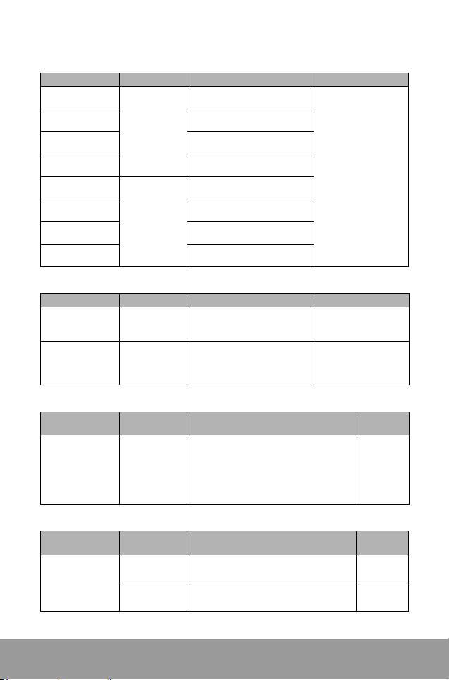
NX7 Product List
Base Module
Catalog number Input power I/O specifications Remarks
NX7-28ADR
NX7-28ADT
NX7-48ADR
NX7-48ADT
NX7-28DDR
NX7-28DDT
NX7-48DDR
NX7-48DDT
100 to 220V ac
power supply
24V dc
power supply
Expansion Module
Catalog number Input power I/O specifications Remarks
NX7-28EDR
NX7-28EDT
24V dcb power
supply
24V dc power
supply
Programming Software
Programming
software
WinGPC 3.5
(Windows)
Catalog
number
16-point dc input/12-point relay
output
16-point dc input/12-point
transistor output
28-point dc input/20-point relay
output
28-point dc input/20-point
transistor output
16-point dc input/12-point relay
output
16-point dc input/12-point
transistor output
28-point dc input/20-point relay
output
28-point dc input/20-point
transistor output
16-point dc input/12-point relay
output
16-point dc input/12-point
transistor output
Specifications Remarks
Allows you to perform the following tasks
on a remote computer:
PLC program editing and monitoring, file
-
management, program backup, online
editing, error and status check-up, network
status check-up, I/O mapping, time chart
monitoring
Built-in 9k steps
memory,
Several
µ
s per step
processing speed
Built-in 1 HSC input
channel,
Built-in 2 pulse output
channels built in,
2 communication ports
(NOTE: Some relevant
contacts are unavailable
when HSC input or
pulse output channels
are used.)
16-point 24V dc input
12-point relay output
2A per point
16-point 24V dc input
12-point transistor
output
4A per point
For
Windows
95/98/
2000/NT
Communication
cable for both
RS232 and
RS485
8
Item
Cables
NX_CBLCPU2
NX_CBLCPU5
Catalog
number
Specifications Remarks
PLC to PC communication (WinGPC)
2 m
Same functions with NX _CBLCPU2
5 m
 Loading...