


,
I
OPERATING
INSTRUCTIONS
!'\l\-I:\'
-!o
\1\-
3'2.
l'l-OS·~'8'-.
OS-3Z12-
,
0':1-3171- - '
G5...QJ41-£
0;-3\131-
11
05-oo15-S
Model 35P Proof Chronograph
Oehler Research, Inc.
Post Office
Box
91:!5, Austin, TX
78766
Phone
512.327.6900 sal
es@oehler-research.com

CONTENTS
Condensed Instructions ........................................................ 1
Proof
Channel Background .................................................. .2
Skyscreen JII Background .................................................... .3
Program Switches ................................................................. 4
Metric Velocities ................. ................................................. .5
Skyscreen Mounting .............................................................. 6
Actual Chronographing ................................... ..................... 8
Printer Output ............... .............................. ...... ........ ......... 10
Summary .............................................................................
11
Banery ................................. ...............................................
12
Edit Mode ...........................................................................
13
Printer Paper ......................................................................
14
In Case
ofTrouble
.............................................................. 15
Glints ..............................................................
..
..................
17
Orange Diffusers Can't Always Help ................................. 18
Subsonic Velocities ............................................................. 1 8
Bows ...................................................................................
19
Shotguns ............................................................................. 19
Indoor Shooting .......
..
....... .................................................. 19
Downrange Velocities .... .........................................
....
....... .20
Muzzle Velocities
from
Instrumental ..........
.... ..
..................
20
Wounded Skyscreens ............................ .............................. .20
Standard Deviation
and
Load Development ..................... .21
Carrying Case ............. ... ............................ .......................
.25
Specifications ..................................................................... .26
Warranty ............................................................................ .29
Oehler Research, Inc.
Post Office Box 9135
Austin, Texas
78766
Telephone
512/327·6900
FAX
512/327·6903
sales@oehler-research.com
Copyright 1991,
2010
PROOF CHANNEL TM, PROOF CHRONOGRAPH
1M
and GLINT PROOF""
are trademarks
of
Oehler
Research,
Incorporated.
Take your Model 35P to the range, set it up, and shoot.
If
everything doesn't
work perfectly, you can then read the instructions.
Some read only this. first
page, but the rest
of
the book
will
help you get better results. We
try
to cram
forty·plus years
of
chronograph experience and the essence
of
thousands
of
conversations with users into this little book. Thank you for buying
our
product; we look forward to hearing from you.
CONDENSED INSTRUCTIONS
-+
Mount the sky screens on the rail. Use the dimples to get the correct
spacing.
Use thumbscrew with ntiddle screen.
-+
Remove bolt and place rifle on rest.
Aim
at downrange target.
-+
Place the fIrst stand approximately 8 feet from muzzle with the second
stand approximately
4'
farther downrange. Place skyscreen/rail
assembly on stands with the long bolts
fItting into tops
of
stands.
-+
Locate your head so that you look through the skyscreen window as
you look into the muzzle and see a centered bore. Adjust height and
position stands until
all are centered on boresight line.
-+
Verify gun is sighted at target and thru skyscreen windows. Any shot
hitting the target will pass through the skyscreen windows. Leave the
fore end rest in position and you can change guns.
-+
Plug skyscreen cables into the M35. Plugging
in
the start cable turns
the system on. Push reset button until you see
---
0.
-+
Fire through skyscreens. The shot number and then primary velocity
will be displayed.
It
prints proof velocity, shot number, and primary
velocity.
-+
If
the
PROOF
CHANNEL
detects an error, the display flashes and an
asterisk is printed alongside the velocity.
You can use the
OMIT
button
10
erase any velocity thaI you suspect is incorrect. Fire
additional shots as desired.
-+
Push the SUMMARY button. Printer will show high, low, extreme
spread, average or mean, and standard deviation for printary channel.
-+
Fire more shots to add to the same group, or push the RESET button to
start a new group.
Page J

PROOFCHANNELBACKGROUND
Professional users have long recognized the convenience
of
skyscreens.
These same users have also recognized limitations in the reliability
of
sky screens. With skyscreens you are at the mercy
of
the light conditions
existing at the range. Skyscreens work well under most conditions, but under
certain rare light conditions there will be errors.
If
you haven't yet found.
these conditions, you will. Errors are seldom, and users will forgive the
system
if
the chronograph flags those shots that may contain errors.
The
proof channel in the Model 35P
wams
you
of
any measurement error.
If
you set your screen spacing accurately, the proof velocities should be very
near the primary velocities. The
proof
velocities are measured from start
screen to the middle screen; the primary velocities are measured from start
screen to stop screen.
If there's a significant difference between primary and
proof velocities, the M35 waves a flag.
If
the spacing between screens is
incorrect, expect larger (but fairly consistent) differences on each shot. For
example,
if
you move the proof screen more than a quarter inch from the
exact midpoint, you will see the flashing display.
The
proof channel shows
the importance
of
accurate and adequate screen spacing.
The
proof channel
can't measure screen spacing for you, but it sees your errors.
The
size
of
the
differences on each shot is comparable to the size
of
typical errors in your
velocity measurements.
The
proof channel tells you when to trust the
chronograph velocity reading, and when the system is fooled by light
conditions.
We
could have made the proof channel so that the differences would be much
smaller. For instance, if you use only two screens to drive two
chronographs; they will read the same on each shot and prove nothing. An
error at either screen causes an identical error in velocity for each
chronograph.
You can use two pairs
of
screens with both start screens
adjacent and both stop scrcens adjacent.
You get maximum spacing on both
pair, but conditions will likely affect both pair in the same way and still prove
little. The configuration
of
the M35 was chosen so that an error at
anyone
or
two skyscreens causes a difference in velocity readings. This difference is
your warning
of
a measurement error.
Page 2
SKYSCREENBACKGROUND
We
've shipped Sky screen
ill
units with Oehler chronographs since 1984.
Thousands
of
shooters have been pleased.
The
Skyscreen
ill
was the first
handloader skyscreen to use lenses, and the units have been refined to near
perfection.
We
imprOVed the shielding
of
the cable so you'
ll
see fewer false
triggers from static electricity and electrical interference.
We
reinforced
the
rugged single-bolt mounting system so you can't pop the mounting bolt from
the case.
For years other manufacturers ridiculed our use
of
diffusers; now
our
most
vocal critics advocate diffusers and sell their imitations. We've gone a step
farther and have improved ours for better performance.
The
new diffuser's
special blaze orange material gives the highest sensitivity with early
and
late
light.
The
translucent material tames the brightest noonday sun while
the
new wider diffuser and the new lens hood protects the lens from the glare
of
mid-day sun.
The
diffusers won't flutter in the wind and they easily absorb the blast
of
the
biggest guns. They will not survive direct bullet hits. Still, the side rails flex
to protect your skyscreens
if
your mounting rail takes a tumble. All parts,
including the skyscreen cases, are molded
of
tough polycarbonate. There's
no metal to rust
or
kink, and there's no glue to
faiL
Best
of
aU,
the window is
larger so they are easier to shoot through without fear
of
damage.
The
4'
rail provided with your system reflects our industrial experience.
We
know that longer
is
better. A one-foot spacing between screens in inherently
twice as accurate as is a six-inch spacing. A two-foot spacing is twice
as
good as the one-foot spacing.
The
four-foot spacing is twice
as
good
as
the
two-foot spacing. We stop there because
we've
found that that four-foot rail
is
as long as we can conveniently haul to the range. The rail includes
dimples to hold three skyscreens at precise spacing. As you tighten the
114"-
20 mounting screw
of
each skyscreen into its dimple you get exact screen
spacing. Dropping the bolt tails into the tops
of
the stands may appear crude,
but it works well and you need no tools at the range.
The
two folding stands
are more convenient and reliable than is a single camera tripod.
Page 3
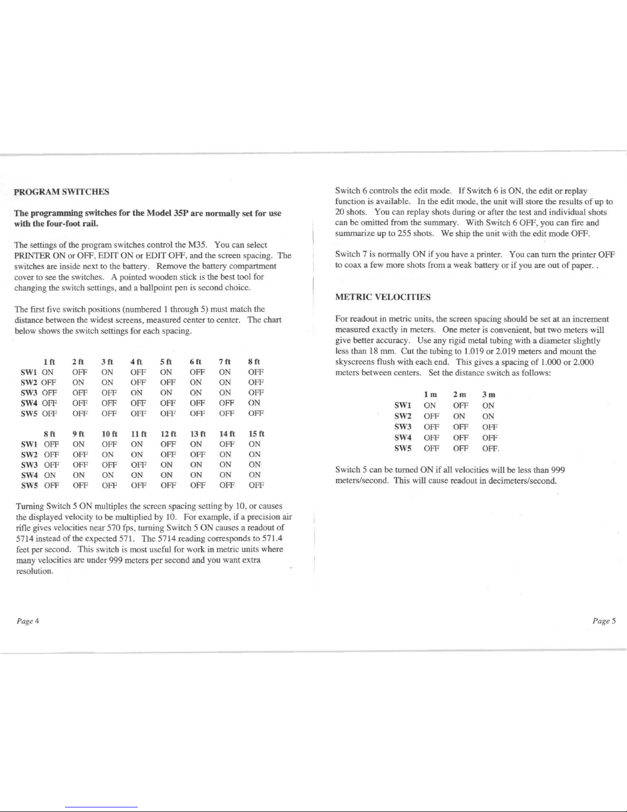
PROGRAM
SWITCHES
The programming switches for the Model
35P
are
normally set for
use
with
the four-foot rail.
The settings
of
the program switches control the M35. You can sele<;t
PRINTER
ON
or
OFF, EDIT
ON
or
EDIT
OFF,
and the screen spacing.
The
switches are inside next to the battery.
Remove the battery compartment
cover to see the switches. A pointed wooden stick
is
the best tool for
changing the switch settings, and a ballpoint pen is second choice.
The
first five switch positions (numbered I through 5) must match the
distance between the widest screens, measured center to center.
The
chart
below shows the switch settings for
each
spacing.
Ift
2ft
3ft
4
ft
Sft
6ft
7ft
8ft
SWI0N
OFF
ON
OFF
ON
OFF
ON
OFF
SW2 OFF
ON
ON
OFF
OFF
ON
ON
OFF
SW3 OFF OFF OFF
ON
ON
ON
ON
OFF
SW4 OFF
OFF OFF
OFF
OFF OFF OFF
ON
SWS
OFF
OFF OFF
OFF OFF
OFF OFF OFF
8ft
9ft
10 ft
11ft
12
ft
13ft
14
ft
15
ft
SWI OFF
ON
OFF
ON
OFF
ON
OFF
ON
SW2 OFF OFF
ON ON
OFF OFF
ON
ON
SW3 OFF
OFF
OFF OFF
ON
ON ON ON
SW4
ON
ON
ON
ON
ON
ON ON
ON
SWS
OFF OFF
OFF
OFF OFF OFF OFF OFF
Turning Switch 5
ON
multiples the screen spacing setting by 10,
or
causes
the displayed velocity to be multiplied
by
10.
For
example,
if
a precision air
rifle gives velocities near
570 fps, turning Switch 5 ON causes a readout
of
5714 instead
of
the expected 571.
The
5714
reading corresponds to 571.4
feet per second. This switch is most useful for work in metric units where
many velocities are under 999 meters
per
second and you want extra
resolution.
Page 4
Switch 6 controls the edit mode.
If
Switch 6 is ON, the edit
or
replay
function is available. In the edit mode, the unit will store the results
of
up to
20 shots. You can replay shots during
or
after the test and individual shots
can
be
omitted from the summary. With Switch 6 OFF, you can fire
and
summarize up to 255 shots.
We
ship the unit with the edit
mode
OFF.
Switch 7 is normally
ON
if you have a printer. You can turn the printer
OFF
to coax a few more shots from a weak battery
or
if
you are
out
of
paper. .
METRIC
VELOCITrES
For readout in metric units, the screen spacing should
be
set
at
an increment
measured exactly in meters .
One
meter is convenient,
hut
two
meters will
give better accuracy.
Use
any rigid metal tubing with a diameter slightly
less than 18 mm.
Cut
the tubing to 1.019
or
2.019 meters and
mount
the
sky screens flush with each end. This gives a spacing
of
1.000
or
2.000
meters between centers.
Set the distance switch as follows:
1m
2m
3m
SW1
ON
OFF
ON
SW2 OFF
ON ON
SW3 OFF OFF
OFF
SW4 OFF OFF
OFF
SWS OFF OFF
OFF.
Switch 5 can
be
turned
ON
if
aU
velocities will
be
less than
999
meters/second. This will cause readout in decimeters/second.
Page 5

SKYSCREEN MOUNTING
Use the 4' rail with a light stand
under each end. Mount start and
stop skyscreens using a 3"
threaded stud with attached wingnut as the mounting screw.
The
long tail
of
each stud slips into the
hollow center post
of
a stand.
Make
sure that the screws fit into
the dimples
of
the rail. Tighten
each thumbscrew and stud
firmly
by hand.
We
prefer a 4' screen spacing for
general use.
If
you must have
longer
or
shorter rail, use half-inch
EMT
(thin-wall electrical conduit)
cut
an inch longer than the desired
screen spacing. You can use
longer screen spacing for improved
accuracy,
or
a shorter rail for
convenience.
If
you choose
longer screen spacing, we suggest
one that fits inside your vehicle for
transport to the range. Regardless
of
the length
of
the rail, the third screen
mounts midway between the two primary screens.
We discourage the use
of
two-piece rails.
They
usually sag
at
the coupling,
and the uncertain sag cancels the benefits
of
the longer spacing.
Page 6
It is convenient to "bundle" the cables from the sky screens . .
Gather
all three
cables together near where the cable exits from the start skyscreen. Place a
wrap
of
tape (electrical tape, masking tape, or whatever is handy)
around
the
cables at this point. Repeat the tape wrap every foot until you get
to
the
other end.
The
shortest cable end is obviously from the
STOP
screen;
plug
it in first. Plug the middle length cable into the MrD jack. Finally plug the
longest
end
into the
START
jack. Even
if
you remove the skyscreens
from
the rail, just coil the bundled cables
'lasso"
fashion and you'll have little
trouble with tangles.
You must mount a diffuser
over
each skyscreen. Slip a
black
side-rail into your skyscreen,
hook one end
of
an
orange
diffuser into the standing side-
rail, hook a second side-rail
onto
the diffuser, and then slip the last
end into the skyscreen.
Page 7
 Loading...