

Page 1
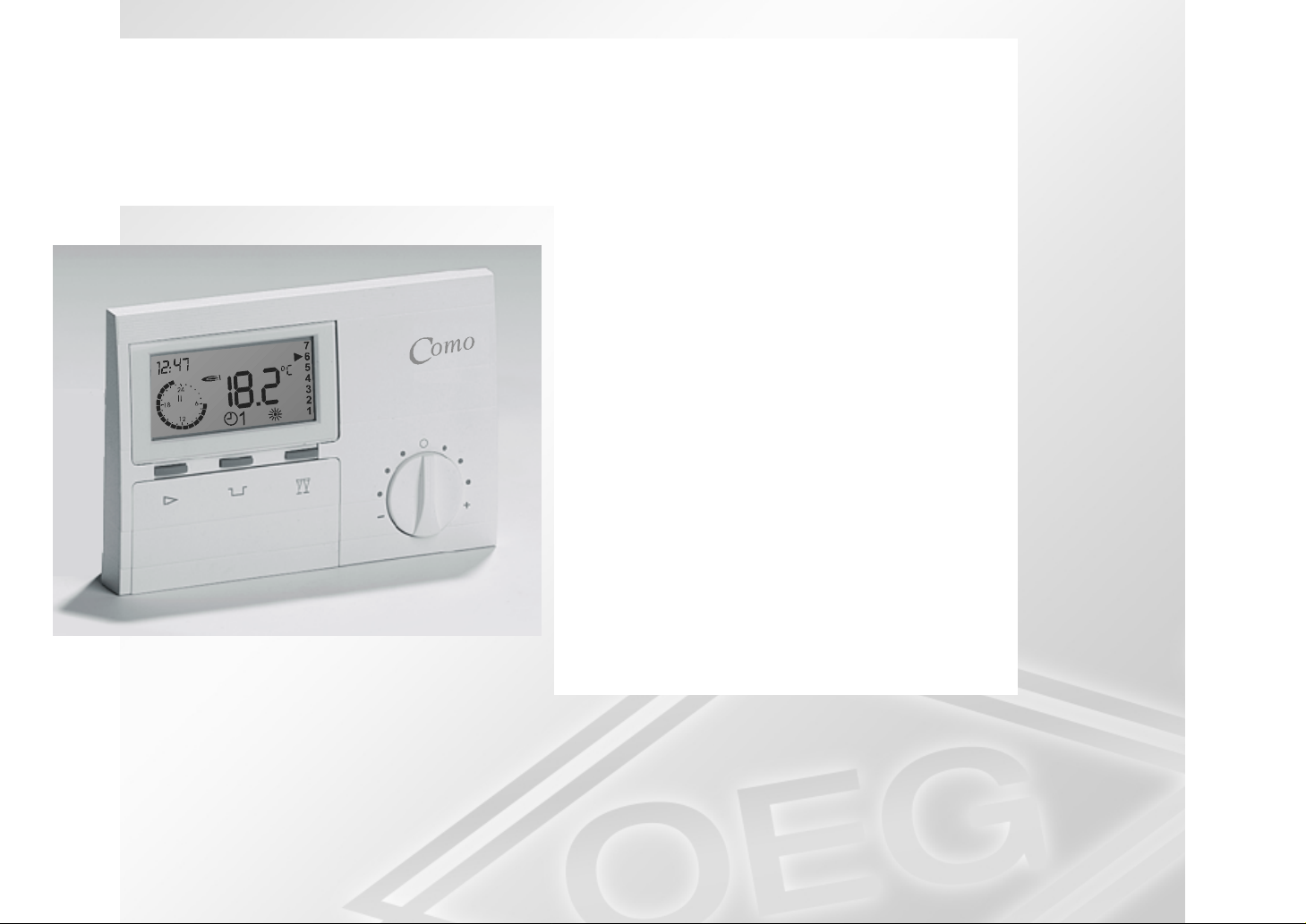
Room controller Como
Operating and
Installation Instructions
Please follow the safety information and
read through these Instructions carefully
before placing the system into operation.
Page 2
Safety information General
General
Safety informati on
General
This attent ion symbol is used in
these Instructions to point out
risks and dangers to the life and
limb of persons and/or damage to
property.
Power connection regulations
Please note the connection condi tions
specified by your loc al elect r ical power
supply utility and the VDE regulat ions.
Your heating control system may be
install ed and servi c ed only by appropriatel y authorised special ists.
If t he system is not i nstalled professionally, this will involve a risk
to life and limb.
Declaration of conformity
Como
corresponds to the requir ements of the
relevant guidelines and standards, if
the corresponding installat ion regula-
tions and the m anufactur er ’s instruc-
tions are complied wit h.
Descriptio ns of op erat ing
procedures
Certain operating sequences are explained using examples. The statuses
of the controller are illustrated or described as boxes. The following status
can be accessed by operating t he operating cont rols as shown or by performing the operation described.
Key sym bols:
Operate m ode-selector switch
Press ECO key
Press Party key
Press Programming key
Press Plus key
Press Minus key
Notes
Warranty conditions
If t he system is not i nstalled, c ommissioned, serviced and repai red professionally, this will render the manufacturer’s warranty null and void.
2
!
Import ant informat ion is highlighted
with an exclamation mark .
Page 3
Operation Operating controls
Operation
Operating contr ols
7
a
6
5
4
3
2
1
1
b
ABC D
Commissioning
!
Please do not f orget: Rem ove t he
protecti ve film from t he battery
contacts (see Chapter Battery
change).
After correct installation, it is first necessary to enter the l anguage, the time
and the day of the week in order to operate the controller:
Correcting t he desired room
temperature
The rotary knob can be used to adjust
the programmed desired room tem peratures by ± 5°C. T he set r educ ed
temperat ure is not influenced. The corrected desired value is displayed as
DES ROOMT E MP at level " P ar ameter"
(is updated every 10 s).
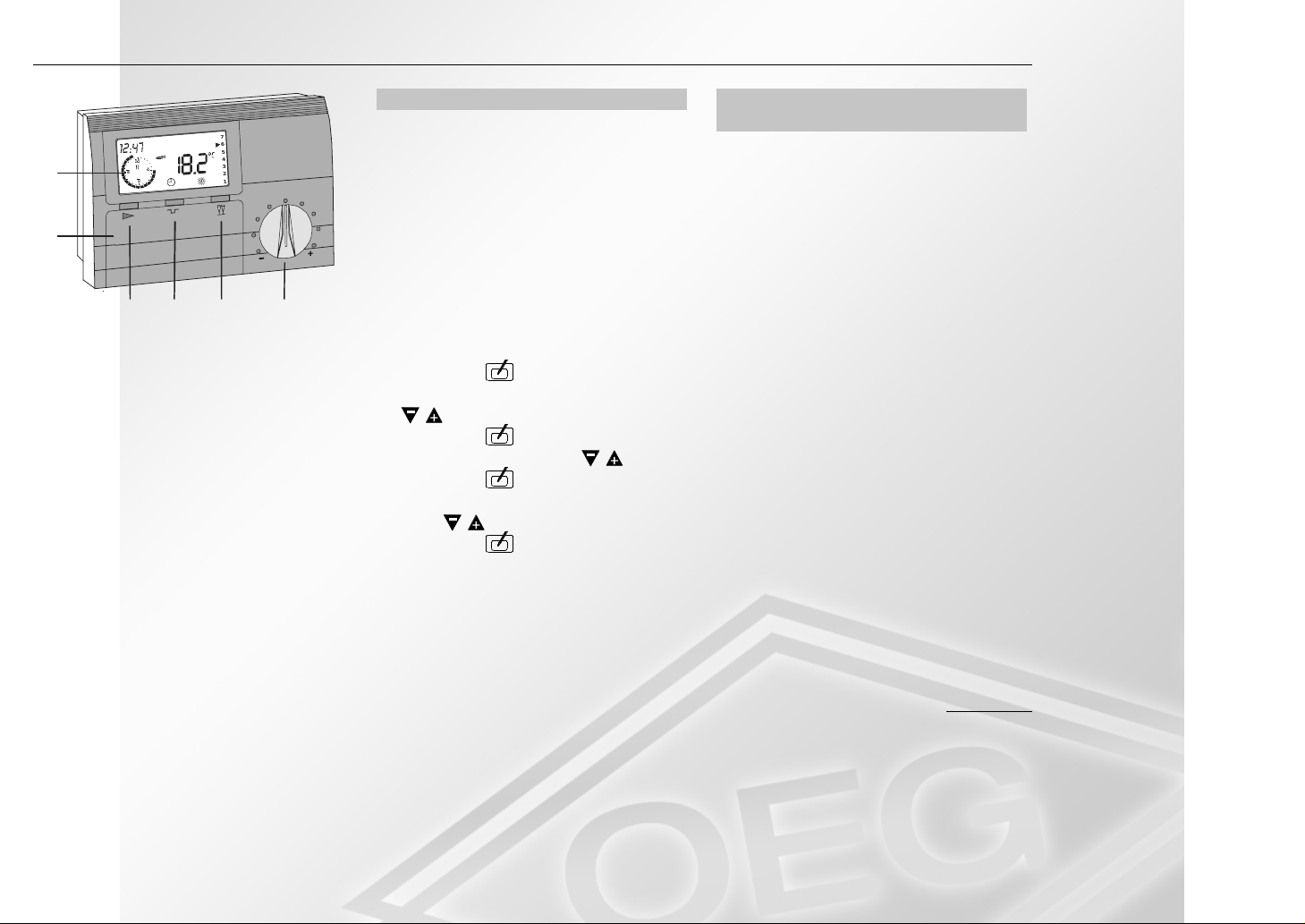
a Display
b Hinged control panel cover
A Mode-selector switc h
BECO switch
(interr upting the heating time)
C Party switch
(prolonging the heating t ime)
D Rotary knob for desired val ue
entry
1. Open the hinged front panel (b).
2. Press key
.
3. Select the language with k ey s
/ .
4. Press key
5. Set the time with keys
6. Press key
twice.
/ .
.
7. Set the day of the week (1-7) with
keys
8. Press key
/ .
.
9. Close the hinged front panel (b).
The control ler is now ready for operation!
3
Page 4
Operating controls Operation
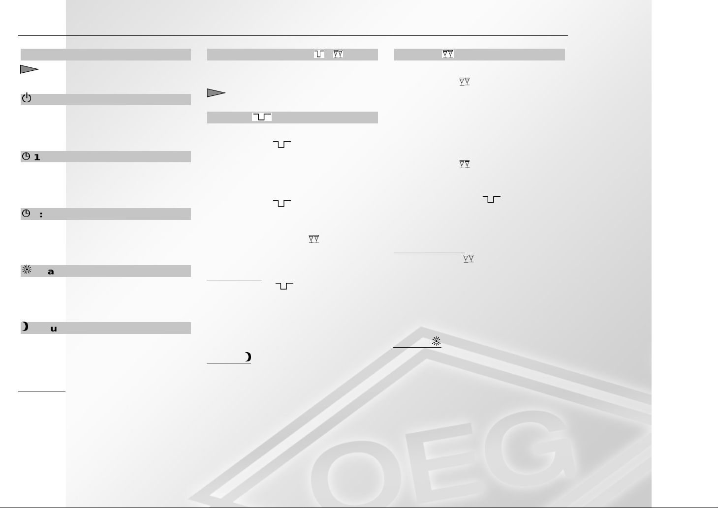
Mode-selector switch
: Change the operating mode.
!
Takes effect after 3 seconds.
-
Frost-protection mode
The control ler is switched off. The
desired value f or the room t em-
perature is set to 5° C.
5
1: Heating program 1
(Automatic 1) Automatic change of
the desired room temperatures at
the programmed switching tim es.
5
2: Heating program 2
(Automatic 1) Automatic change of
the desired room temperatures at
the programmed switching tim es.
Heating mode
The controller constantly stabilises
the system to desi r ed r oom temperature 1.
Reduced night operation
The control ler operates constantly in
ECO mode and stabilises the system to the set economy temperature.
Heating time changes /
The heating t ime change is terminated
by pressing the mode- sel ec tor switch
.
ECO key
In Heating mode:
Each time key
heating ci r c uit switches to Reduced
mode f or 1 further hour .
In Reduced mode (E CO):
Each time key
duced mode is prolonged by one hour.
Pressing the Party k ey
set interruption by 1 hour.
Sleep mode:
If the ECO key is pressed for
longer than 3 seconds, the r oom controll er switches to Reduced mode r egardless of the heating program until
the first heating tim e of the next day.
Display:
is pressed, the
is pressed, Re-
shortens the
Party key
In Reduced mode (E CO):
Each time key
heating ci r c uit switches to Heating
mode with the desired room t emperature of the last heating time for one
further hour.
In Heating mode:
Each time key
heating peri od is prolonged by 1 hour.
When the ECO key
this shortens the set heating time extension by one hour.
Non-Stop mode:
If the Party key is pressed for
longer than three seconds, the room
controller switches to Heati ng mode
with desired room temperature 1 regardless of the heating program until
the first heating tim e of the next day.
Display:
is pressed, the
is pressed, the
is pressed,
4
Page 5
Operation Operating controls
M
L
DFC
Display
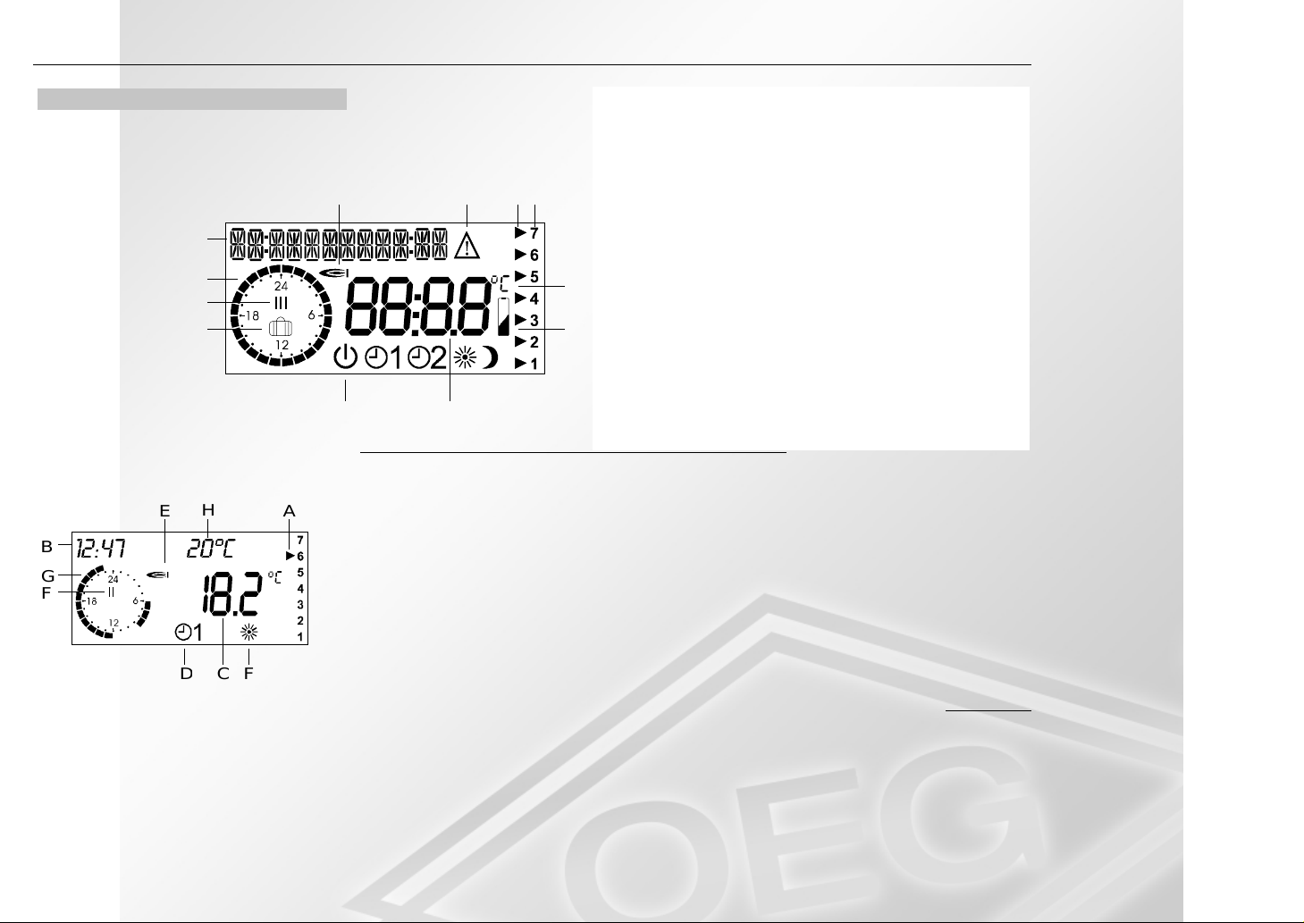
Como f eatures a liquid-crystal display
(LCD) displaying
all relev ant data.
A
B
C
D
H
B
G
F
E
&
A
A Plain-text display and time
B 24h clock for display of the cur r ent heating
times
C Display of the curr ent heating time (1- 3)
EFH I
The standard display shows the following i nformation:
A: It is Saturday
B: The time is 12:47
C: The current room temperature is 18.2°C
D: The current operating mode of the contr ol is Automatic 1
(Heating on the basis of the heating times in heating program 1)
E: The system is in Heating mode
(The relay is closed; the burner is on resp. the valve i s open)
F: The system is in the second heating t ime
G: Heating m ode on S aturdays (A): from 6 am to 9 am and from 12 am to 11 pm
H: Optional: The cur r ent desired room tem perature is 20°C
D Symbol for Holiday mode (f r ost pr otection)
E Symbol for burner in Heating mode
F Warning symbol: "Param eter may be adjusted“
G Symbol for cooling in Cooling m ode
H Ar row points to current day of the week
J
I Days of t he week (1- 7 => Monday-S unday )
J Degrees Celsius
K
K Note: "Change battery“
L Parameter value display
M Symbols for cur r ent operating mode:
[Standby (frost protec tion), A utomatic 1, Automati c 2, Heating mode, Reduced (night) mode]
5
Page 6
Settings Operation
Settings
Changing the settings
Opening the hinged control panel
cover c auses the operation-cont r ol
module t o swit c h automaticall y to Information and Pr ogr amming mode.
The operating c ontrols are assigned a
new significance (which can be seen
from the printed designations which will
now appear beneath the keys).
All entries can be made on t he basis
of the same principle
1. Open the hinged cover on t he front
of the controller; the contr oller
switches to I N FO mode. The three
keys are then assigned the function
printed on the inside of the hinged
cover.
2. Choose the required parameter of
the current level or another level
with keys +/-.
3. Press the Programming key
4. If you press k ey
and have se-
.
lected a lower operating level
-> continue at P oint 2!
5. If you press k ey
and have selected a setting, the controller
changes to Program m ing m ode
AB
C
E
GHFD
(Programming indicator ).
6. The parameter v alue c an be
changed with keys
7. Press key
again; this saves the
or .
new value.
8. If you close t he hinged c ov er before
pressing key
, this quits Programming mode. T he c ontroller
switches to t he s tandard display
(boiler temperat ur e and time). The
changed value is not saved.
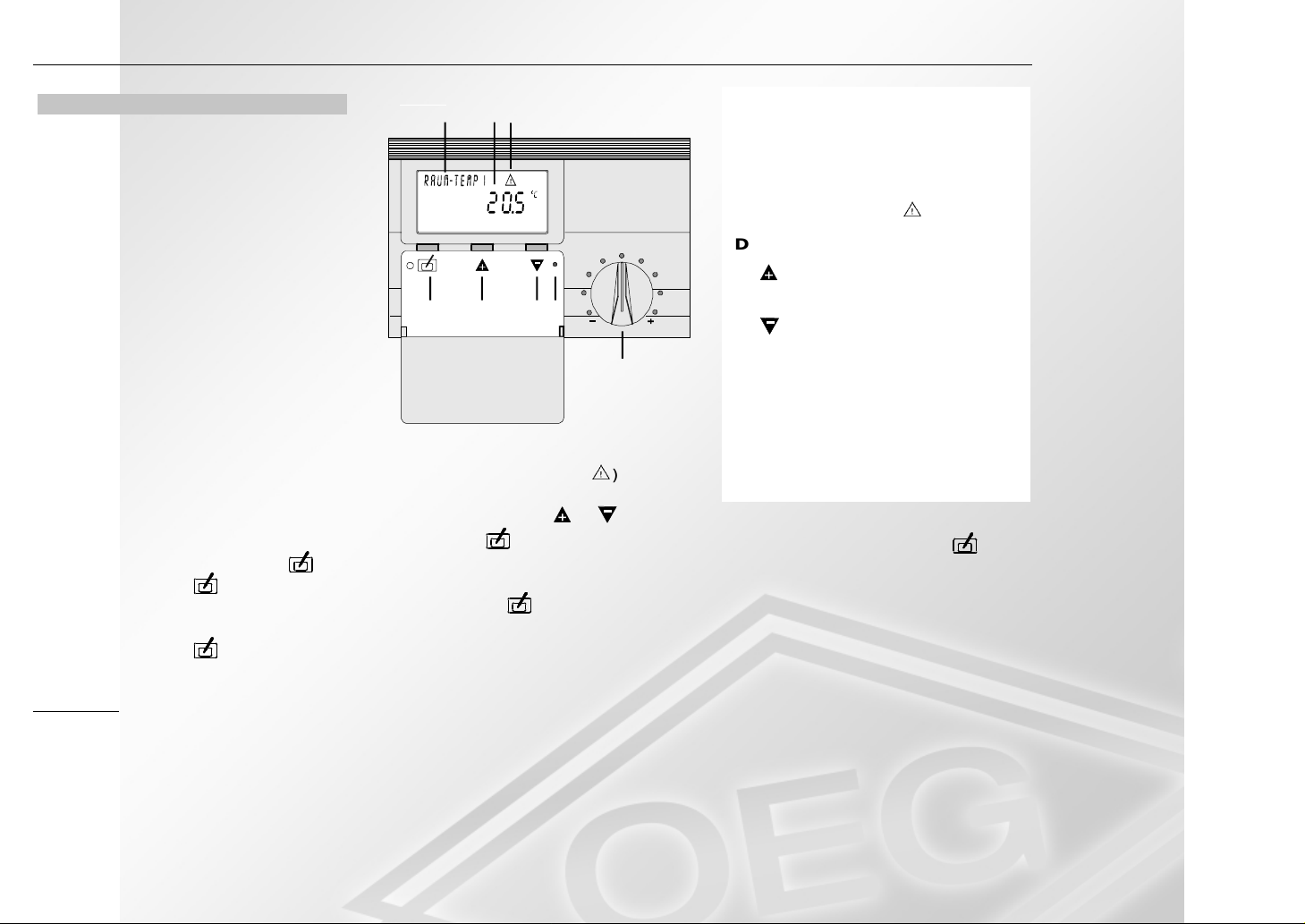
A Designat ion of the entry or of
the operating level.
B Entry
C Progr amming indi c ator
(W arning triangle
)
D Progr amming key
E
key: Next setting /
increm ent setting
key: Previous setting /
F
decrement setting
G RESET switch
H Desired room temperature
correction
!
You can branch up to the next operating level by pressing key
selecting t he "RETURN" function.
and
6
Page 7
Operating levels Settings
Operating levels
Operatin g levels
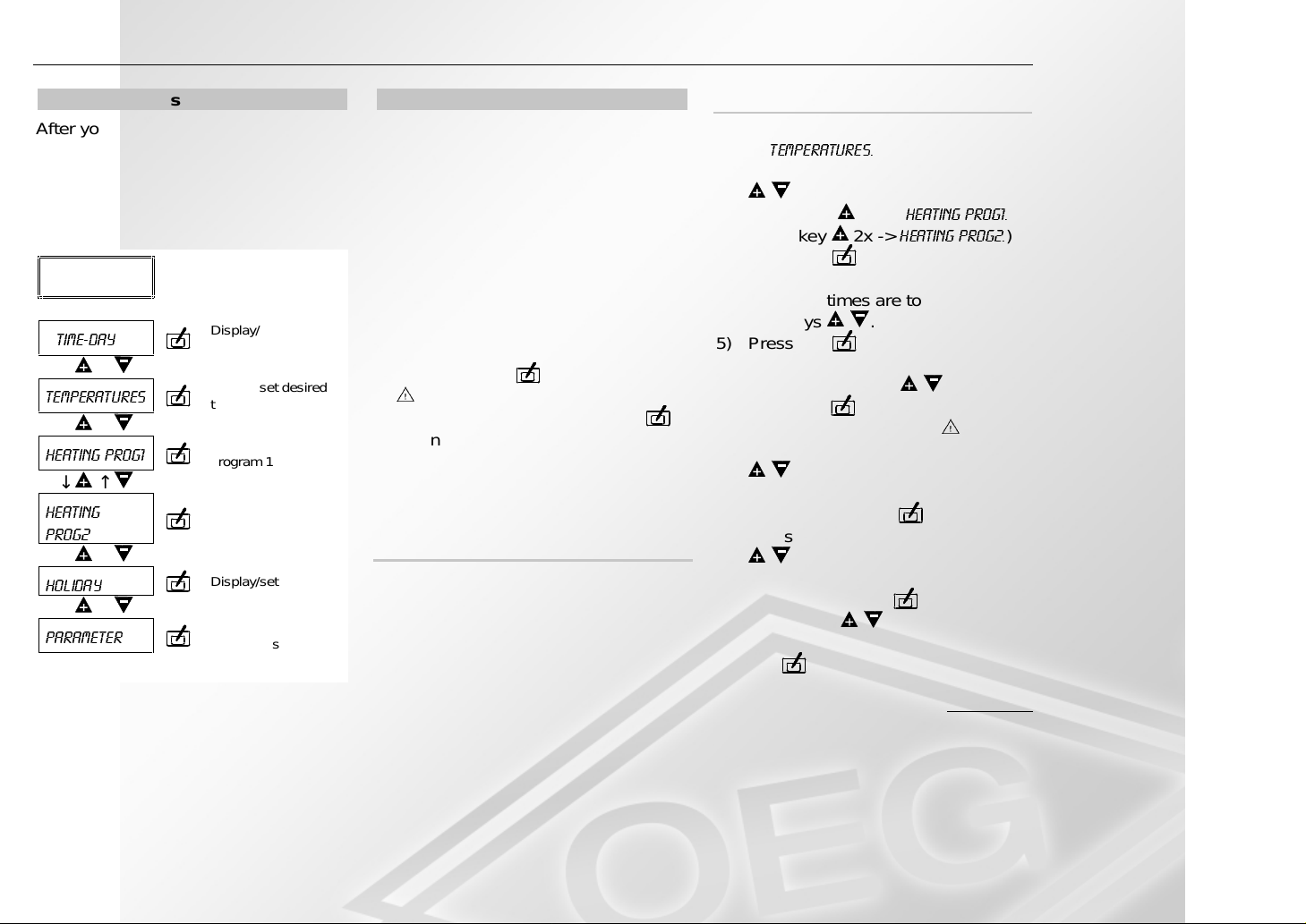
After y ou open the hinged contr ol panel
cover (Info mode), you c an c hoose six
different oper ating level s wit h the
+/- keys. Y ou c an ac tivate the selec ted
level by pressing the P r ogramm ing
key.
Open hinged
front panel
⇓
7,0('D\
Displ ay/set desired
time and day
↓ ↑
7HPSHUDWXUHV
Displ ay/set desired
temperatures
↓ ↑
+HDWLQJ3URJ
Displ ay/set heating
program 1
↓ ↑
+HDWLQJ
3URJ
Displ ay/set heating
program 2
↓ ↑
+ROLGD\
Display/set holidays
↓ ↑
3DUDPHWHU
Display/set
parameters
Heating Prog1 / Heating Prog2
The BM allows entry of two heating
programs between which the user can
select.
!
If switching time entry in blocks (MoFr, Sa-Su, Mo-Su) is activated, the
current switching times of the first
day of the block are di spl ay ed. The
display does not show the switching
tim es of the entire block. If y ou ac tivate a switching time with the Programm ing key
) and then save the v alue by
(Warning tr iangle
pressing the Programming k ey
again. Al l switching val ues i n the
block are overwrit ten by the switching values of the first day in the
block!
Recommended procedure
1) Enter all heating times for the period Monday-S unday ( overwri te all
switching times of the week!) .
2) Enter differ ent switching times for
the corresponding days.
Entry of the heating programs
1) Open the hinged front panel
7HPSHUDWXUHV
->
2) Select a heating program with keys
.
1x ->
+($7,1*352*
.
+($7,1*352*
)
(Press key
Press key 2x ->
3) Press key
4) Select the period f or whic h the
switching times are to be defined
with keys
5) Press key
.
.
6) Select the heating time to be
changed with keys
.
7) Press key
(Program ming i ndicator ).
8) Adjust heating tim e star t with keys
.
9) Save new or unchanged heat ing
time start with key
.
10) Adjust heating time end with keys
.
11) Save new or unchanged heating
tim e end with key
12) Using keys
, select next
.
heating time or "RE TURN". Press
key
.
RETURN => Next l evel up
7
Page 8

Settings Operating levels
Parameter
Room sensor adaptation
The actual display can be vari ed by
± 5 K in order to adapt the room temperature displ ay to the instal lation c onditions or other therm ometers. T he c or rected display value is used in the
calculations for all relevant functions.
Display
This parameter all ows you to set
whether the current desi r ed r oom temperature is shown on the display.
Warm-up optimisation
War m-up optimi sation determines the
optim um advance time of star t of
heating. T he tim e advance ensures
that the heated r ooms hav e r eac hed
their desir ed temperature at the switchon tim es of the heating times.
Display: Last t ime advance required
Setting: Maximum time adv anc e
Control I/0 <=> Proportional
Selection between two-point and proportional c ontrol.
CONTROL I/0
Heating m ode starts if the actual tem-
perature drops below the room tem perature by the displayed amount [K].
If t he temperat ur e is exceeded by t he
amount [K ], Heati ng mode ends. A
minimum switch-on/switch-off time can
be set with the delay set ting.
PROPORTIONAL control
Heating m ode is switched on for a per-
centage (50 %) of the adjustable cycle
tim e as a functi on of the deviation between the measured and desired t emperature of the room. The hysteresis
setting allows you to set an allowable
deviation from the desired tem perature. This avoid short On times of the
boiler.
CONTROL OFF
No control function. The relais switches
only ti me dependent.
Heating/Cooling
The control ler can also be used f or
controlled cooli ng of rooms. If the
"Cooling" function is selected, the connected cooling system is closed if the
desired temperature is ex ceeded by
the set hysteresis and is opened if the
actual temperature dr ops bel ow the
desired temperature. In P roportional
mode, the r elay is also switched as a
function of the control devi ation. T he
greater the set desir ed temperat ur e is
exceeded at t he instant of comput ation, t he longer the cooling system r emains active.
Telephone switch/window contact
Telephone switch: The controller
switches to Heating mode for as long
as the contact between ter minal s 3/4 is
closed.
Window contact: The controller
switches to Frost-prot ec tion m ode
for as long as the c ontact between
terminals 3/4 is i nterrupted.
-
8
Page 9
Operating levels Settings
Settings
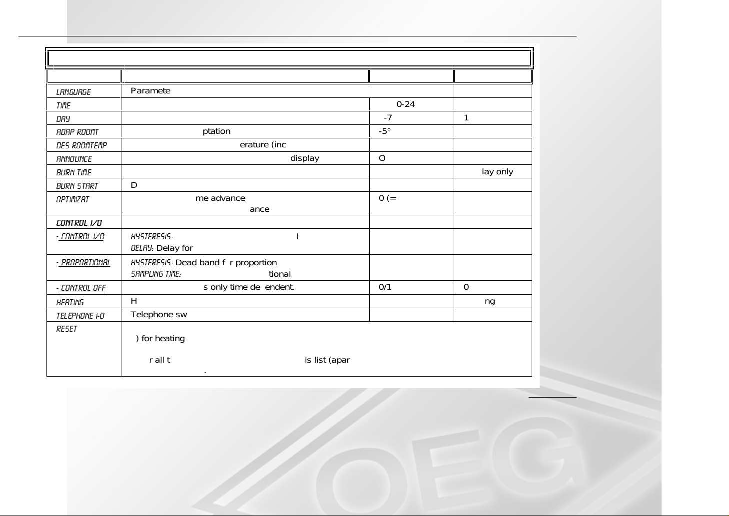
Parameter Designation Adjustment range Factory default
/$1*8$*(
7,0(
'$<
$'$352207
'(652207(03
$11281&(
%8517,0(
%85167$57
237,0,=$7
&RQWURO,
&RQWURO,
3URSRUWLRQDO:+\VWHUHVLV
&RQWURO2II
+HDWLQJ
7HOHSKRQHL
5HVHW
Parameter designation language D GB F NL E I German
Time 00:00-24:00 10:00
Day of week 1-7 1 (Monday)
Room sensor adaptation -5°C - +5°C 0°C
Current desired room temperature (incl uding correction) Display only
Desired room temperature on standard display On/Off Off
Display of burner operating time in hours Display only
Display of burner starts Display only
Display of last t i me advance required
Setting of maximum time advance
Control I/0 or Pr opor t i onal mode Control I/0
+\VWHUHVLV
:
'HOD\
6DPSOLQJWLPH
The relais switches only tim e dependent. 0/1 0
:
Heating or cooling mode H, K Heating
Telephone switch or window contact T, F Telephone I-0
Load factory default:
1) for heating program 1 or
2) for heating program 2 or
3) for all t em peratur es and all settings of this l ist (apart from l anguage, time and date)
4) or for all values.
Hysteresis for ON/OFF control
Delay for relay state
Dead band for proportional mode
Cycle time for propor t i onal mode
0 (= Off) - 3
hours
0.1 K - 2.0 K
0-30 min
0 K – 2.0 K
0-30 min
2 hours
0.4 K
0 min
0 K
10 min
9
Page 10
Accessories Operating levels
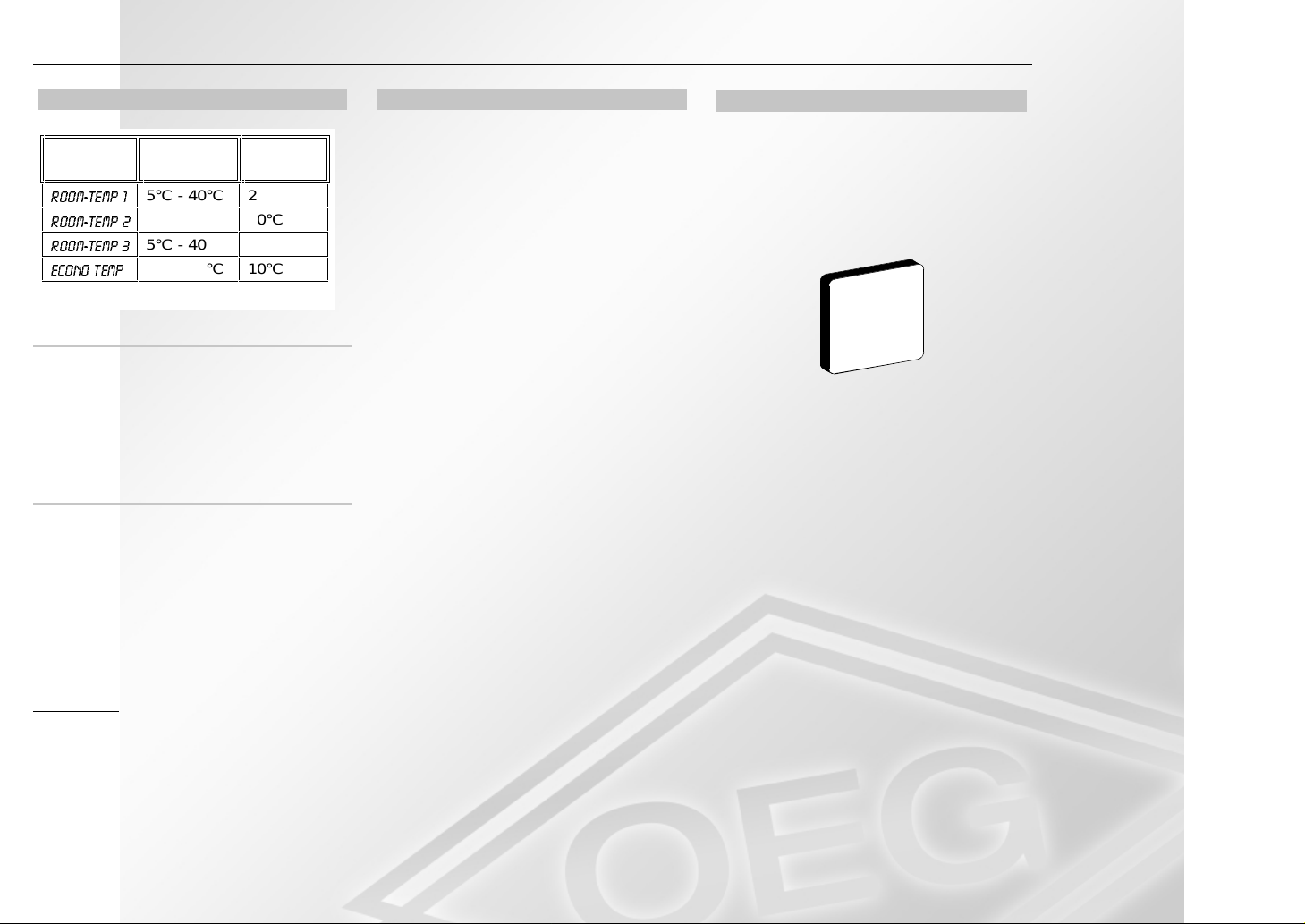
Temperatures
Display Adjust ment
range
52207(03
52207(03
52207(03
(&2127(03
5°C - 40°C 20°C
5°C - 40°C 20°C
5°C - 40°C 20°C
5°C - 40°C 10°C
Factory
setting
Room temperature
This parameter all ows you to progr am
the required desi r ed r oom temperature
for the three heating tim es. The entered value is set by t he c ontrol on the
basis of the integrated room sensor.
ECO-TEMP
The reduced temperature or economy
temperat ure represents the temperature to which the system stabilises outside the heating tim es, e.g. during the
nighttime or during ECO mode.
Holiday
You can use the controller’s Holiday
program during the holiday period. The
duration of the holiday and the hol iday
start are entered in days. The Holiday
program is always activated at 12. 00
hours and always ends at 24.00 hours
of the last day of the holiday .
!
If t he holiday period is entered before 12.00 hours, the Holi day pr ogram start s on the day of entry ( S HOLIDAY= 00; with S-HOLI DA Y =05
in 5 days). If the hol iday period is
entered after 12.00 hours, the pr ogram start s on the next day at 12.00
hours. It thus al so ends one day
later.
The control ler switches to Standby
mode during the holiday . The Holiday
symbol i s shown on the display . Holiday mode is terminated by operati ng
the Program switch.
Accessories
External room sensor RFB
Installation location:
• In the main cont r olled z one of the
heating circuit (on an interior wall in
the living room).
• Not in the vicinit y of radiators or
other appliances emitting heat.
Installation:
1. Use a screwdriver t o lev er the cap
off of the bas e; see illustrat ion
overleaf.
2. Attach the bas e at the installat ion
location.
3. Make the electrical connections.
4. Press the cap back on.
10
!
Please check batt eries!
Page 11
Operating levels For the fitter
FGH
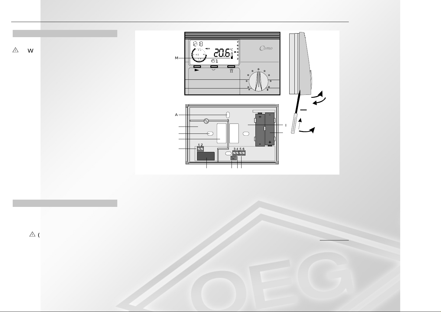
Battery change
7
6
5
4
3
2
2
1
When the batteries reach a low
charge state (M), the system
switches to Heating mode. (Relay
: :
M
1
contact i s closed -> burner /
pump is on resp. valve is open).
!
Always dispose of spent batt er ies
properly (spent battery col lecti on
point).
Swivel upper part of controller upwards
„c“. The two batteries must be c hanged
within 2 m inutes. If the battery change
should last longer , press the Reset
button and reset time and weekday
A
B
A
C
D
147x97x34
I
J
c
d
K
a
b
(see Reset function). Then re-engage
the top section at the upper edge of the
socket and swivel it back onto the base
"d“. Press on until the top section engages in position.
For the fitter
Installation
A Hole for fasteni ngs screw
B Terminal compartm ent for mains
voltage
(always reclose the cover af-
ter connection)
C Break-out opening for c able
D Connection terminals for the re-
lay (beneath t he c over)
E 250 V AC 10(2) A relay
F Plug connection for c ontroller
G Terminal 3+4 for telephone
switch / window contact
E
H Term inal 5+6 for RFB
external room sensor
I Terminal compartm ent for extra-
low voltage
J Batteries: 2 x 1.5 V round c ell
LR6 / AA / AM3
11
Page 12
For the fitter Operating levels
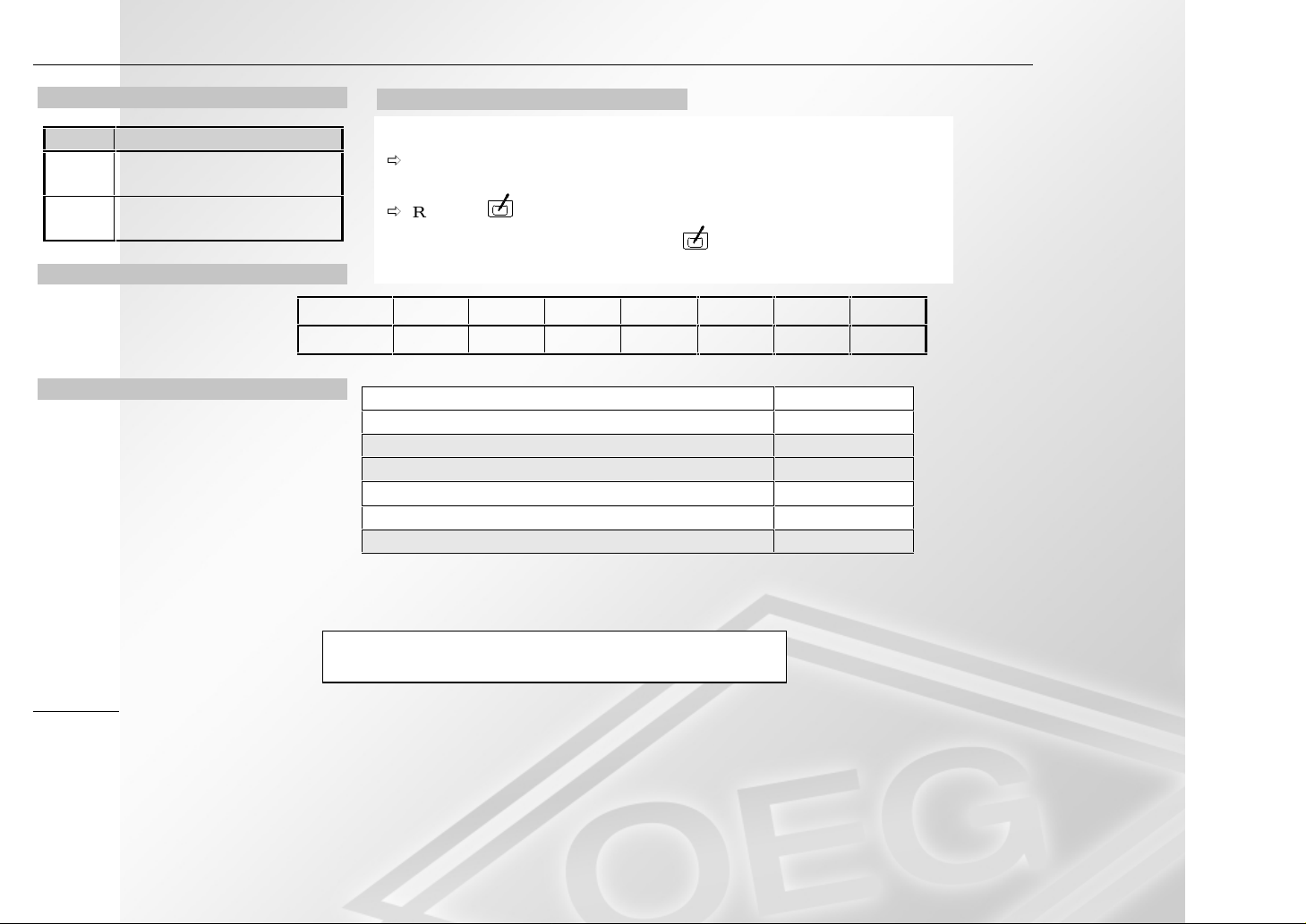
Errors
Error Error designation
E 80 Room sensor defect iv e
Discontinuity/short c ircuit
E 81 EEPROM error
Check settings.
Sensor resistances (RFB)
The sensor resistances must
be measured in the base wit h
the control ler rem oved.
Technical ratings
RESET function
In case of err or function or to restore manufac turers set-up
Õ
RESET: The controller performs a restart. The controller will work with
the adjusted values. Only time and weekday have to be reset.
Õ
RESET + : This overwrites all parameters with default values.
!
You must press the additional key when you release the
RESET key.
Temperature 5°C 10°C 15°C 20°C 25°C 30°C 35°C
Resistance
12,700 Ω 9,950 Ω 7,855 Ω 6,245 Ω 5,000 Ω 4,030 Ω 3,265 Ω
Supply voltage 2 ea. round cell batteries LR6/AA/AM3 3 V DC
Switching capacity of the relays 250V 10 (2) A
Enclosure to EN 60529 IP 40
Safety class to EN 60730
Power reserve of the timer (bat tery change)
Permitted am bient temperature during operation 0 to 50°C
Permitted am bi ent tem peratur e for st or age -30 to 60°C
II, totally insulated
> 2 min.
12
Malfunctions attributable to incorr ect operation or setting are
not covered by warranty.
CC/V 1100 6.6701.196-01 Printed in Germany. Subject to modification.
 Loading...