

OEC Medical 7000 Compact User manual
Technical -
Documentation
7700
C om pact
Wilhelm Maiselstr. 14
D - 90530 W endelstein
T el. + +49 / 9129 / 28283-30
Fax + +49 / 9129 / 28283-28
REVISION 3.0b
18. Jan 2001
00-441017-03
77c00_03.ds4

FU SE LIS T for 7700
Fuse Rating M odel Location Funktion Functional Schem atic Diagram
F1 15A
20A
F2 15A
20A
F3 2A P ow er P late A ssem bly A C IN P ow er O n
F4 10A P ow er P late A ssem bly 24VA C P ow er O n / C arm Lift / kV G eneration & R egulation / m A G eneration & R egulation / Interconnect S chem atic
F5 1.6A P ow er P late A ssem bly 220V AC M onitor R otation / Interconnect S chem atic
F1 500m A B 206-8 A C IN B 206 schem atic / Fluoro M ode C ontrol Logic / Film M ode C ontrol Logic / Im age S ystem
F1 50m A B 111 A C IN P ow er O n
F2 50m A B 111 A C IN P ow er O n
F1 50m A Com pact B 111M R A C IN M onitor R otation
F2 50 m A C om pact B 111M R A C IN M onitor R otation
F1 100m A S eries B 116 A C IN P ow er O n
F2 315m A S eries B 116 5V D C B 104
F3 315m A S eries B 116 5V D C B 104
F4 315m A S eries B 116 24V AC M onitor R otation
F5 315m A S eries B 116 5V D C B 104
200-240V
100-130V
200-240V
100-130V
Power Plate Assembly AC IN Power On
Power Plate Assembly AC IN Power On
F1 2A NG 1 (B420)
N G 2 B 430)
F2 2A NG 1 (B420)
N G 2 B 430)
F1 2.5A B 143 24V D C m A G eneration & R egulation
F1 2.5A M onitor B G 641 220V AC P ow er O n
F2 2.5A M onitor B G 641 220V AC P ow er O n
F608 1.25A M onitor W M N
F 2,5 A M onitor W M 3819 220V AC P ow er O n
F 4A Series Im age Processor 220V AC P ow er O n
F 4A Series Im age Processor 220V AC P ow er O n
F 500m A S eries M onitor H C C 220V AC P ow er O n
F 500m A S eries M onitor H C C 220V AC P ow er O n
F1 1.6A S eries B117 H C C 2 9V AC P ow er S upply for B 108
F2 500m A S eries B 117 H C C 2 9V A C P ow er S upply for B 108
F3 100m A S eries B 117 H C C 2 220V AC P ow er S upply for B 108
F4 100m A S eries B 117 H C C 1 & H C C 2 220V A C P ow er S upply for B 108
F5 800m A S eries B 117 H C C 1 & H C C 2 9V AC P ow er S upply for B 108
A C IN P ow er O n
A C IN P ow er O n
1 . k V C o n tro l L o g ic
2. kV D isplay C ontrol
+
16V (X 1-3A )
GND (X1-32A)
+12V
12
Reg
U26
+16V S (X 1-4A )
+5VS (X1-5A)
GNDS (X1-31A)
B 64 B O A R D
MP3
+12V
1 . C o n tro l P a n e l In terface
2 . k V C o n tro l L o g ic
3 . m A C o n tro l L o g ic
4. II M ag M ode C ontrol
5. Fluoro & Film M ode C ontrol L ogic
6. H and and F ootsw itch M onitoring
+ 5 V (S T 1 -1 A )
+16V (ST 1-3A )
MP1
MP2
GND
-5 V
8
5
Reg
U16
+5V S (ST 1-5A )
MP4
GNDS
B 300 B O A R D
D58
G reen
D57
G reen
B 101 B O A R D
1 . Iris C o n trol
2. Fluoro E xposure T im e C ontrol
3. Fluoro B eep C ontrol
+ 5 V (S T 1 -A 1)
+16V (ST 1-A 3)
MP1
GND
MP2
1. Film E xposure T im e C ontrol
+ 5 V (S T 1 -A 1)
+16V
MP1
MP3
MP2
GND
B 102 B O A R D
1 . Im ag e P ro c e sso r Inte rfa c e
2. Fluoro M ode C ontrol L ogic
3 . M o n ito r X ra y L a m p C o n tro l
4 . M o n ito r "H o m e P o sitio n in g "
V C C S Y S = 5 V S T 5 - 1 / S T 9 - 1 A /C
G N D S Y S = S T 1 -1 /2 / S T 9 - 3 2 A /C M P 1
VCC = 5V ST5-3
G N D = S T 5 -4 M P 2
V C C V B S = 5 V S T 3 - 1 7
GNDVBS = ST3-25 M P3
B 300 B O A R D
ST1ST1ST9ST1ST1ST1
B 64 B O A R D
FREE SLO T
B 304 B O A R D
B000 1 MO THE R BO AR D
B 102 B O A R D
B 101 B O A R D
FREE SLO T
B 143 B O A R D
B 304 B O A R D
BR1
VCC
GND
B R 1 C lo s e d fo r C o m p a c t
B R 2 C lo s e d fo r C o m p a c t
BR2
VCCSYS
GNDSYS
B 143 B O A R D
1 . m A C o n tro l L o g ic
+16
+24V (X 2-5)
GND (X2-3)
V (X1-27A)
GND (X1-32A)
7700 C om pact
For R eference O nly
77C 01_02.D S 4
Page 1 of 1
28.July 2000
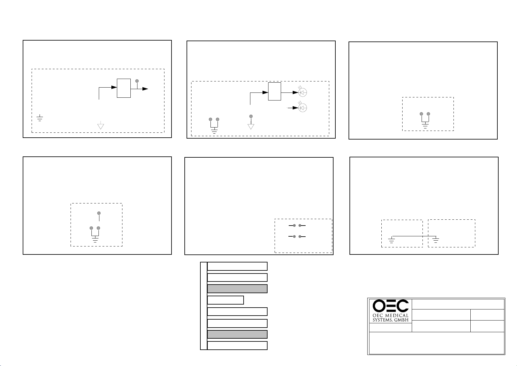
CONTROL RACK BOARDS
POW ER & FUNCTIONAL DESCRIPTION
W3
F2
2A
W1
F1
2A
N G 1 PO W ER SU PPLY
Supplies pow er for:
- Control Rack/Generator
- C a m e ra
- II
R39
90V A C
0V A C
F2
2A
N G 2 PO W ER SU PPLY
Supplies pow er for:
- Im ag e Processor
F1
2A
All relays shown
in the de-energized
AC In
W1W3
F2
20A /110V
15A /230V
K1
R1
F3
2A
20A /110V
15A /230V
F1
T1
0
90V A C
24
10A
24
F4
state
24V A C
BR1
R39
S13
1 5 10 13 11
24
+24V
+16V
+5V
To M onitor R otation diagram
24VDC
EM ERG ENCY
O FF
S27
ST5
1
2
+5V S
+16V S
LED 39
CONTROL PANEL
2
-K O N
S39
ON
S40
O FF
S13
4
6
5
1
+5V
+12V
-12V
X1
1
F1
T1
24V A C
50m A
ST 104
F2
9
3
1
7
10
ST 111
3
1
7
10
X2
24VDC
K1
C2
X3
G1
R1
X4
1
24VDC
D1
24VDC
2
K2
24V D C
X2
13
R3
C1
70m S
Delay
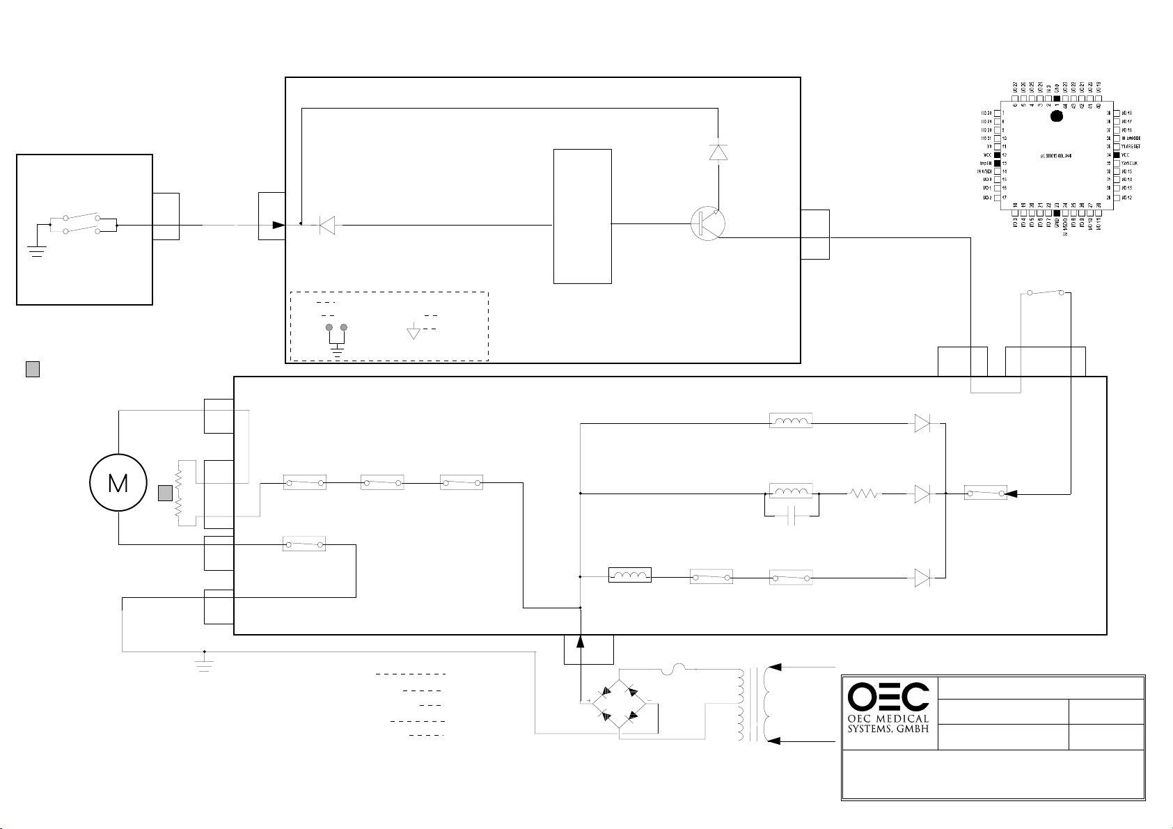
B 79 B O A R D
1. B 111 - relay K 1 energizes w hen the "on"
sw itc h is p re s s e d
2 . P o w e r r e la y K 1 th e n e n e rg iz e s a llo w in g
A C p o w e r to T 1 . T h is in p u t c u rre n t is
lim ite d b y re s is to r R 1
3 . A p p ro x im ate ly 7 0 m s la te r th e p o w e r
re la y K 2 e n e rg iz e s w h ic h a llo w s th e
in p u t c u rre n t to b y p a ss th e c u rre n t lim it
re s is to r R 1
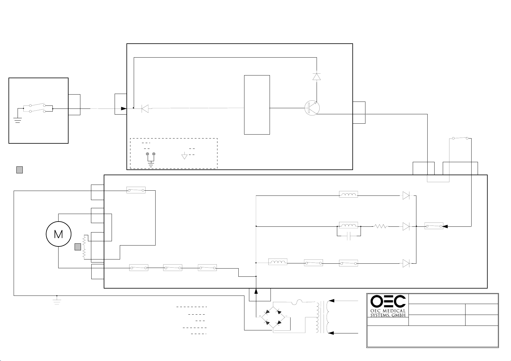
1. B 111 -relay K 1 de-energizes w hen the
" o ff " s w itc h is p re s s e d .
2. Pow er relay K 1 then de-energizes
sh u ttin g o ff A C p o w e r to T 1 .
PO W ER O N
PO W ER O FF
7700 C om pact
F o r R e fe re n c e O n ly
Page 1 of 1
2
1
B 111 B O A R D
77C 02_03.D S 4
21July. 2000
PO W ER O N
W arm up Indicator
16V
CONTROL PANEL
ST1
37
-W A R M L E D
ST2
37
CONTROL LOGIC
IP S L S II0 1 6 -6 0
4
30 SECOND TIM ER
X rays are disabled until the w arm up sequence is com plete
B 300 B O A R D
7700 C om pact/S eries
For R eference O nly
77X03_02.D S 4
Page 1 of 1
21. July 2000
SYSTEM W ARM UP
U5
D25
UP SW ITCH
ST1
S26
38
S29
CONTROL PANEL
G old resisters beneath the B 105 board
1
LIFT
MOTOR
R6
R7
-K C U P
ST2
38
D3
-IN C U P
31
L a ttice
1016-60 9
9
+CU P
T2
5
ST7
-C U P
U PPER LIM IT
SW ITC H
+5V ST1-A1
+16V ST1-A 3
MP1
MP2
+5VS ST1-A 5
ST1-A31
B300 BOARD
X2
K2
2
1
D6
5
L4
X1
1
1
2
L3
K2
67
NO
K3
910
NC
L1
K1
NO
232414
K1
NO
13
24VDC
K4
1
R4
2
D4
K5
2
NC
3
-C U P
C4
K1
1
2
11
K4
NO
10
K5
8
9
NC
D1
B105 BOARD
X35
3
A ll relay contacts are show n in the proper
sta te fo r th e lift m o to r to m o v e u p
K 1 - C u r re n t C o n tr o l
K 2 - D irection C ontrol U p
K 3 - D irection C ontrol D ow n
K 4 - C urrent E nable U p
K 5 - C urrent E nable D ow n
E nergized
E nergized
D e -E nerg iz ed
E nergized
D e -E nerg iz ed
L2
BR1
F4
10A
24VAC
T1
AC Power In
PO W ER O N
fro m
Diagram
7700 C om pact / S e rie s
For R eference O nly
77X 04_02.D S 4
Page 1 of 3
18. Jan 2001
C-ARM LIFT
C-ARM UP M O VEM ENT
U5
D24
DOWN SWITCH
S25
S30
CONTROL PANEL
G o ld re siste rs b en ea th th e B 1 0 5 b o a rd
1
LIFT
MOTOR
ST1
39
R6
R7
-K C D O W N
1
L1
L4
X1
1
2
L3
ST2
39
D4
+5V ST1-A1
+16V S T1-A 3
MP1
K2
10
67
9
NC
K3
NO
MP2
+INCDOW N
+5VS ST1-A 5
ST1-A31
K1
NO
232414
K1
NO
13
L a ttice
1016-60 9
27
24V D C
6
1
+CD O W N
K1
2
T1
B 300 B O A R D
K4
9
NC
-C D O W N
1
1
8
11
K3
K5
C3
K5
NO
ST7
8
2
2
10
R5
X2
D7
D5
D2
LOW ER LIM IT
SW ITC H
10
X38
8
K4
2
NC
3
-C D O W N
B 105 B O A R D
A ll relay contacts are show n in the proper
s ta te fo r th e lift m o to r to m o v e d o w n
K 1 - C u rre n t C o n tro l
K 2 - D irection C ontrol U p
K 3 - D irection C ontrol D ow n
K 4 - C u rre n t E n a b le U p
K 5 - C u rre n t E n a b le D o w n
E nergized
D e -E n e rg ize d
E nergized
D e -E n e rg ize d
E nergized
L2
BR1
F4
10A
24VAC
T1
AC Power In
fro m
PO W ER O N
Diagram
7700 C om pact / S e rie s
For R eference O nly
77X04_02.D S4
Page 2 of 3
21.July 2000
C-ARM LIFT
C-ARM DOW N M OVEMENT
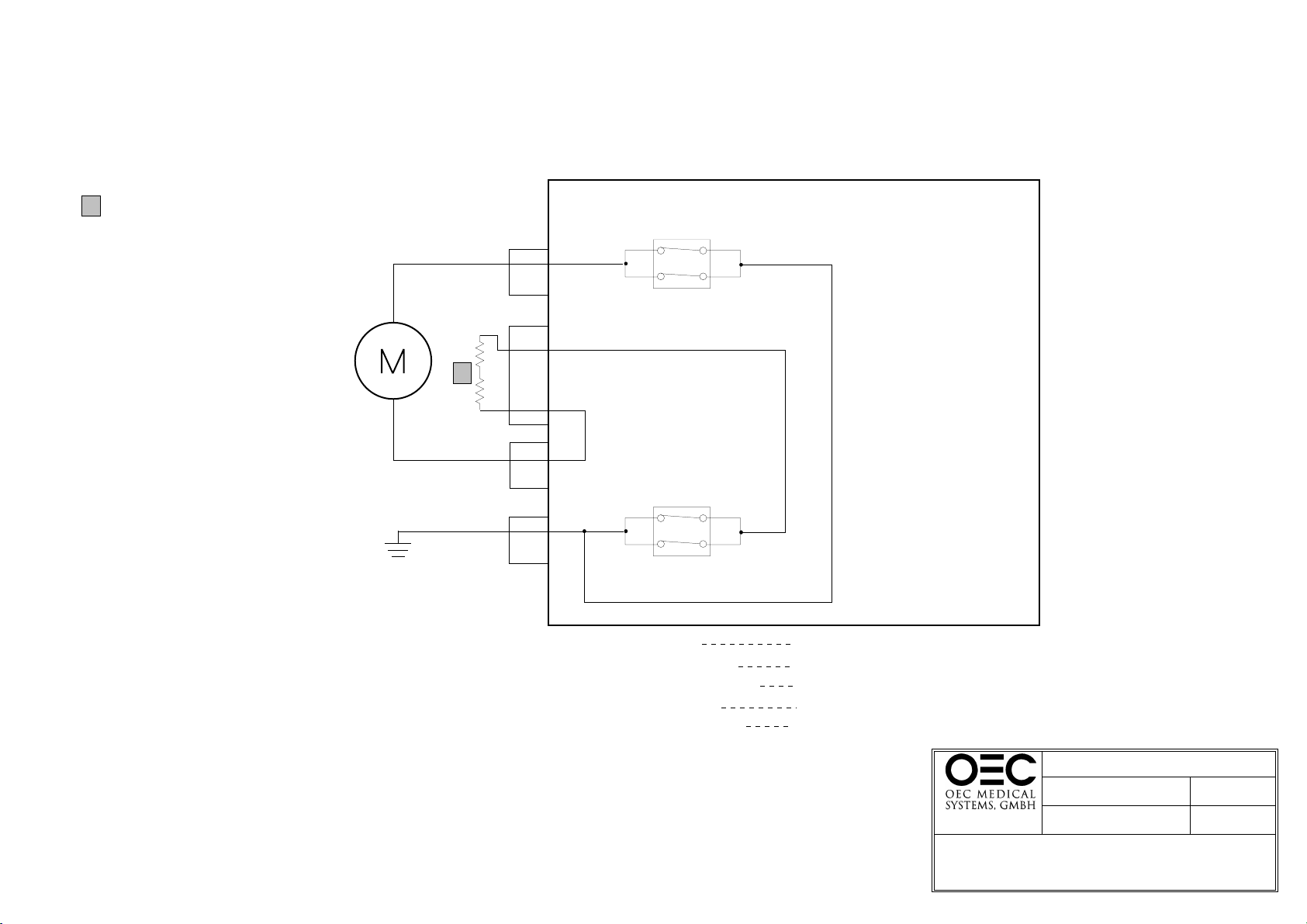
G o ld re sis te rs b e n e a th th e B 1 0 5 b o a rd
1
A ll re la y c o n ta c ts a re s h o w n in th e p ro p e r
state for no lift motor movement
K3
9
10
LIFT
MOTOR
R7
1
R6
L3
5
NC
X1
2
1
L4
K2
9
L1
6
NC
K 1 - C urrent C ontrol
K 2 - D irection C ontrol U p
K 3 - D irection C ontrol D ow n
K 4 - C urrent E nable U p
K 5 - C urrent E nable D ow n
6
10
5
B 105 B O A R D
De-Energized
De-Energized
De-Energized
De-Energized
De-Energized
7700 C om pact / S e rie s
For R eference O nly
77X04_02.D S 4
C-ARM LIFT
NO LIFT M OVEM ENT
Page 3 of 3
21.July 2000
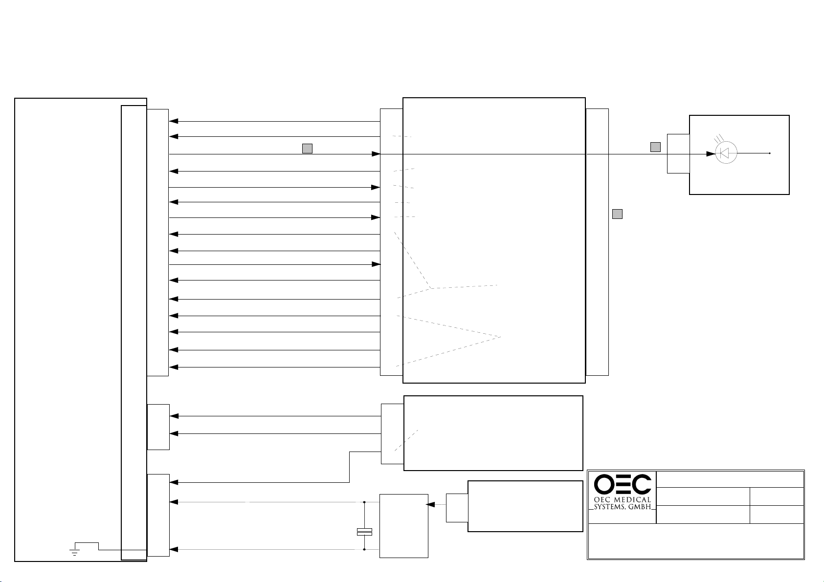
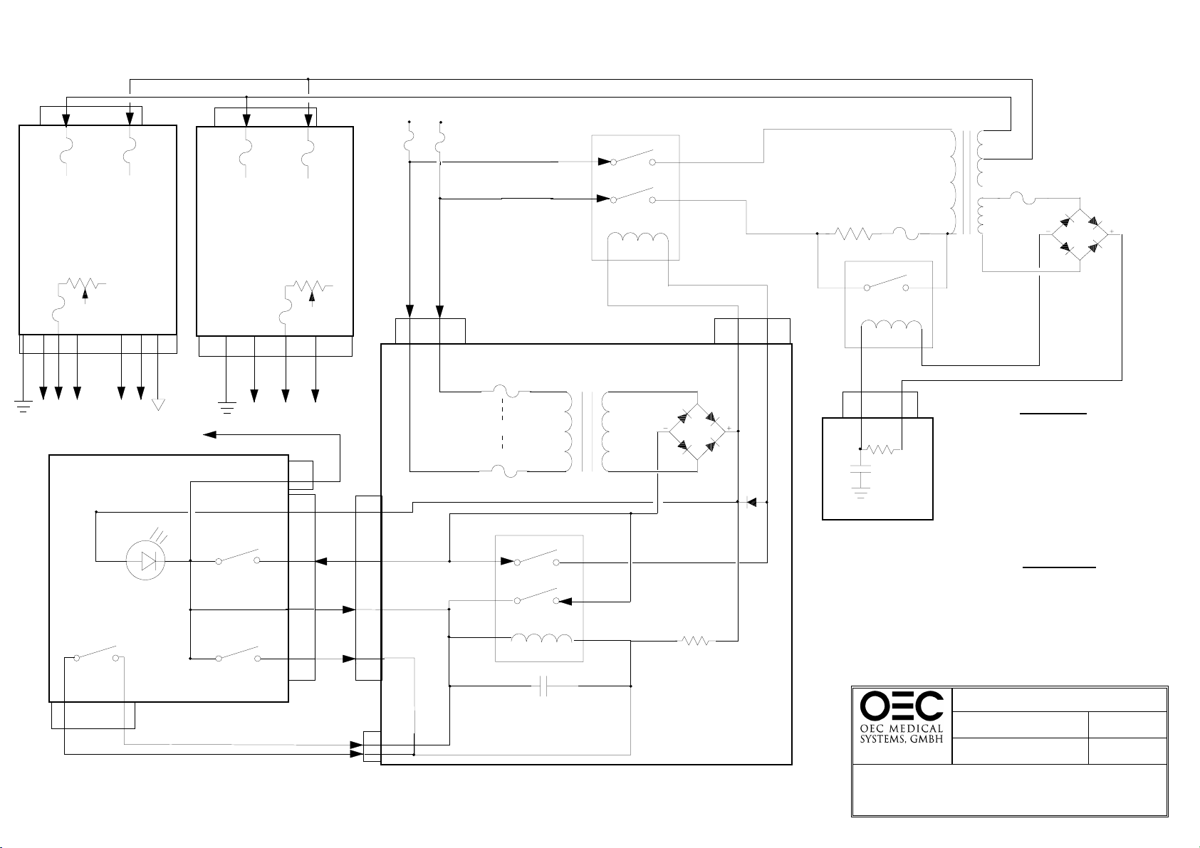
XRAY HEAD TUBE
ASSEM BLY
X3
1
2
3
4
5
-D A (Film M ode Prep, active 1 second prior to film shot)
6
7
8
9
10
11
12
13
14
15
FILTER BOARD
16
-S B Z U (Slot C ollim ator S hutter C lose)
-S B A U F
-SBCCW ( S lot C ollim ator R otate C C W )
-SBCW (S lo t C o llim a to r R o ta te C W )
KV GND
K VSOLL
(Desired KV)
-G E R R
(F au lt)
1
-X R A Y ( X ra y O n )
MAIST (A c tu a l F lu o ro m A )
-Q M A 0 5
+12V D C
(0.5m A m ode)
(F o r Iris P o t)
0V (F or Iris P ot)
PO TIM (I ris P o t W ip e r)
-M IB Z
(Iris C lo se )
-M IB A (Iris O p en )
(Slot C ollim ator Shutter O pen)
ST4
1
2
3
4
5
6
7
8
9
10
11
12
13
14
15
16
B300 BOARD
See kV G eneration & R egulation D iagram
S tarts X ray g eneration,
See Film or Fluoro C ontrol L ogic D iagram s
S ee m A G eneration & R egulatio n D iagram
S ee F ilm M o de C ontrol L ogic D iagram
Lim its fluoro m A to 0.5m A w hen tem perture
is > 62 deg rees C , see m A G eneration &
R egulation D iagram . D isables film m ode,
see Film M o de C ontrol L og ic D iagram
S e e C o llim a to r
C ontrol D iagram
Pages 1 & 2
S e e C o llim a to r
C ontrol D iagram
Page 3
ST2
15
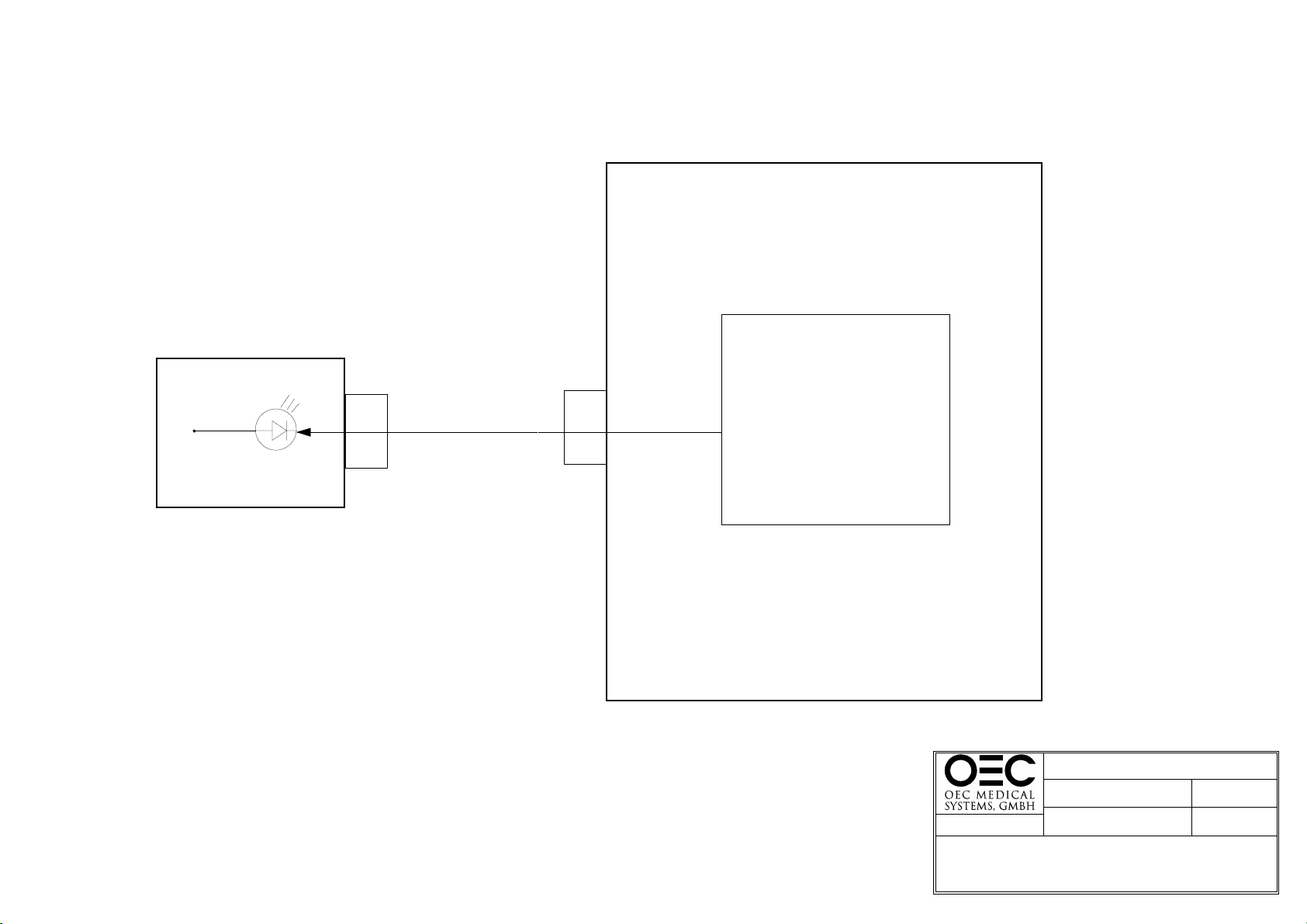
Tem p / E rror Indicator
ST1
15
-G E R R
(F au lt)
1
CONTROL PANEL
1
ERROR CONDITION S
This signal goes true w ith one of the follow ing
conditions, preventing exposure.
1. T em perature > 70 degrees C (T em p Sensor & B 43)
2. UH (Filament Voltage) is too low (0 - 5 VDC)
(B 1 4 3 , B 4 0 & B 4 3 )
T o determ ine if you have a "O ver Tem perature or
"L ow Filam ent V oltage" fault, m onitor U 2 pins 2 & 3
on the B 43 board as follow s:
U 2-3 logic L ow = O ver Tem perature Fault
U 2-2 logic L ow = L ow Filam ent V oltage
S ee the follow ing d iagram s for m ore G ER R details:
1. F luoro M ode C ontrol L ogic
2. F ilm M ode C ontrol Logic
16V
X2
1
2
GND
+16V D C
X1
(Filam ent V oltage)
3
UH
HV SUPPLY
2
A prox 265V D C - Film M ode, H ip M ode, Snapshot M ode
A prox 165V D C - Standard Fluoro M ode, Chest M ode, H and M ode
A prox 125V D C - > 62 D egrees C , Fluoro M ode
4
HV-GND
C1
+
-
X3
2
1
4
X3
S ee m A G eneration & R egulatio n D iagram
Typical 10 - 21 V D C
0 - 5 V D C w ill cause a G E R R F ault
>21 V D C w ill disable X ray generation on the B 143 P cb
~
S ee kV G en eration & R egu lation D iagram
4
BR2
~
B143 BOARD
B79 BOARD
7700 C om pact / S eries
F o r R e fe re n c e O n ly
77X05_02.D S 4
Page 1 of 1
21.July 2000
INTERFACE SIG NALS
XRAY TUBE HEAD TO CONTROL ELECTRONICS
 Loading...