

Page 1

Film-Tech
The information contained in this Adobe Acrobat pdf
file is provided at your own risk and good judgment.
These manuals are designed to facilitate the
exchange of information related to cinema
projection and film handling, with no warranties nor
obligations from the authors, for qualified field
service engineers.
If you are not a qualified technician, please make no
adjuatments to anything you may read about in these
Adobe manual downloads
www.film-tech.com
Page 2

Installation & User Manual for
the Model TM-2 Sound Monitor
Odyssey Product s, Inc.
Page 3

Attention Installer
A protective film covers the LCD Scre en on the TM-2 Monitor. You will need to peel gently to remove this film before using the sound monitor.
Odyssey Product s Inc.
5845 Oakbrook Parkway, Suite G / Norcross, GA 30093 / Phone: 770.825.0243 / Fax: 770.825.0245
Website: odyssey-products.com / E-mail: odysseytechnical@ mi ndspr ing.com
Page 4

TM-2 Monitor Back View
S
Amp
(
)
AMP GAIN
F
U
E
F
U
S
E
F
U
S
E
Data Port 1
Processor Inputs
PRO GAIN
lifier Inputs
Power
Data Port 2
Fuse Holder
1.5 Amp Fuse
DB25 Processor Input
Connector (THX pin-out)
Accepts Odyssey Input 25
card or the TM1-BI card)
**Can be connected directly
to the output of Sony
Processors.
Also accepts the 25/5
parallel input card.
DB37 Amplifier Input
connector. Also
contains the Hearing
Impaired output.
Accepts the Odyssey
TMAMP37 Card
Odyssey Product s Inc.
5845 Oakbrook Parkway, Suite G / Norcross, GA 30093 / Phone: 770.825.0243 / Fax: 770.825.0245
Website: odyssey-products.com / E-mail: odysseytechnical@ mi ndspr ing.com
Page 5

TM-2 Sound Monitor
This product is intended for commercial use and for installation in an equipment cabinet designed for
commercial use. This installation manual is for use by qualified personnel only. Do not open the unit or
perform any servicing unless you are qualified to do so.
Connect the Speakon power connector to the monitor before plugging into the power receptacle. For
protection against electric shock, a three-pin, correctly wired and earthed power outlet must be used. Do
not us a ground-lifting adapter and never cut the ground pin on the three-prong plug.
Check that the correct fuse has been installed. To reduce the risk of fire, replace with fuse only with the
same type and rating.
Odyssey Product s Inc.
5845 Oakbrook Parkway, Suite G / Norcross, GA 30093 / Phone: 770.825.0243 / Fax: 770.825.0245
Website: odyssey-products.com / E-mail: odysseytechnical@ mi ndspr ing.com
Page 6

Input DB25 Board Configuration
(Compatible with THX and Sony Pin-outs)
Channel Terminals On Card DB25 Pin
Left Shield SH 1
Left Plus L+ 2
Left Minus L- 14
Center Shield SH 4
Center Plus C+ 5
Center Minus C- 17
Right Shield SH 7
Right Plus R+ 8
Right Minus R- 20
Left Surround Shield SH 9
Left Surround Plus LS+ 23
Left Surround Minus LS- 10
Right Surround Shield SH 22
Right Surround Plus RS+ 24
Right Surround Minus RS- 11
Subwoofer Shield SH 13
Subwoofer Plus SW+ 25
Subwoofer Minus SW- 12
Left Extra Shield SH 15
Left Extra Plus LE+ 16
Left Extra Minus LE- 3
Right Extra Shield SH 18
Right Extra Plus RE+ 19
Right Extra Minus RE- 6
Odyssey Product s Inc.
5845 Oakbrook Parkway, Suite G / Norcross, GA 30093 / Phone: 770.825.0243 / Fax: 770.825.0245
Website: odyssey-products.com / E-mail: odysseytechnical@ mi ndspr ing.com
Page 7

Pin-outs of the TMAMP37 Card
When used on the back of the Model TM-2 Monitor
Screw Terminals
1Left Low1
2Left Mid20
3Left High2
4 Left Minus (-) 21, 3
6Center Low22
7Center Mid4
8Center High23
9 Center Minus (-) 5, 24
11 Right Low 6
12 Right Mid 25
13 Right High 7
14 Right Minus (-) 26, 8
16 Left Surround + 27
17 Left Surround - 9
(on card)
DB37 Pin
18 Right Surround + 28
19 Right Surround - 10
20 Subwoofer 29
21 Subwoofer- 11
22 Earth 30
23 Earth 12
24 Left Extra Low 31
25 Left Extra Mid 13
26 Left Extra High 32
27 Left Extra Minus (-) 14, 33
29 Right Extra Low 15
30 Right Extra Mid 34
31 Right Extra High 16
32 Right Extra Minus(-) 35, 17
36 Hearing Impaired Sum + 37
37 Hearing Impaired Sun – (earth) 19
Odyssey Product s Inc.
5845 Oakbrook Parkway, Suite G / Norcross, GA 30093 / Phone: 770.825.0243 / Fax: 770.825.0245
Website: odyssey-products.com / E-mail: odysseytechnical@ mi ndspr ing.com
Page 8
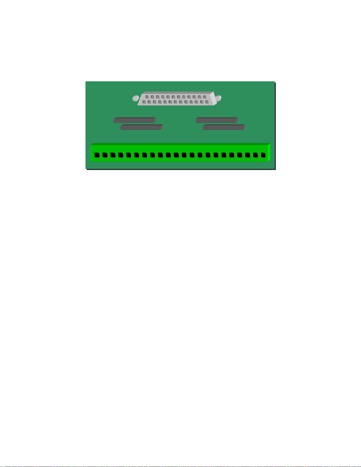
The Odyssey Products TM1-BI Bi-Amp Pr ocessor
Input Adapter Card for the Odyssey TM-1/2
Monitor
PT# TM1-BI ODYSSEY PRODUCTS 770.825.0243
LH LL L- CH CL C- RH RL R- LS+ LS- RS+ RS- SW+ SW- SH LEH LEL LE- REH REL RE-
Fax: 770.825.0245
3. Plug the TM1-BI card into the DB25 Processor Input connector on the back of the Odyssey TM1/TM-2 Monitor.
4. Connect the bi-amped outputs from the processor to the screw-type connector on the TM1-BI card.
5. Connection is made to the 3.5-mm spacing connector on the TM1-BI board as follows.
L.H
- Left Channel High Frequency
L.L
- Left Channel Low Frequency
LC.L
R.H
RLS+
RS+
SW+
LE.H
LERE.L
- Left Channel Minus
(Ground from CP500)
- Center Channel Low Frequency
- Right Channel High Frequency
- Right Channel Minus
- Left Surround Plus
- Right Surround Minus
- Subwoofer Plus
- Left Extra High Frequency
- Left Extra Minus
- Right Extra Low Frequency
Odyssey Product s Inc.
5845 Oakbrook Parkway, Suite G / Norcross, GA 30093 / Phone: 770.825.0243 / Fax: 770.825.0245
Website: odyssey-products.com / E-mail: odysseytechnical@ mi ndspr ing.com
C.H
CR.L
SH
LSRSSWLE.L
RE.H
RE-
- Center Channel High Frequency
- Center Channel Minus
- Right Channel Low Frequency
- Audio Shield (if necessary)
- Left Surround Minus
- Right Surround Minus
- Subwoofer Minus
- Left Extra Low Frequency
- Right Extra High Frequency
- Right Extra Minus
Page 9
User Manual for the TM-2 Sound Monitor
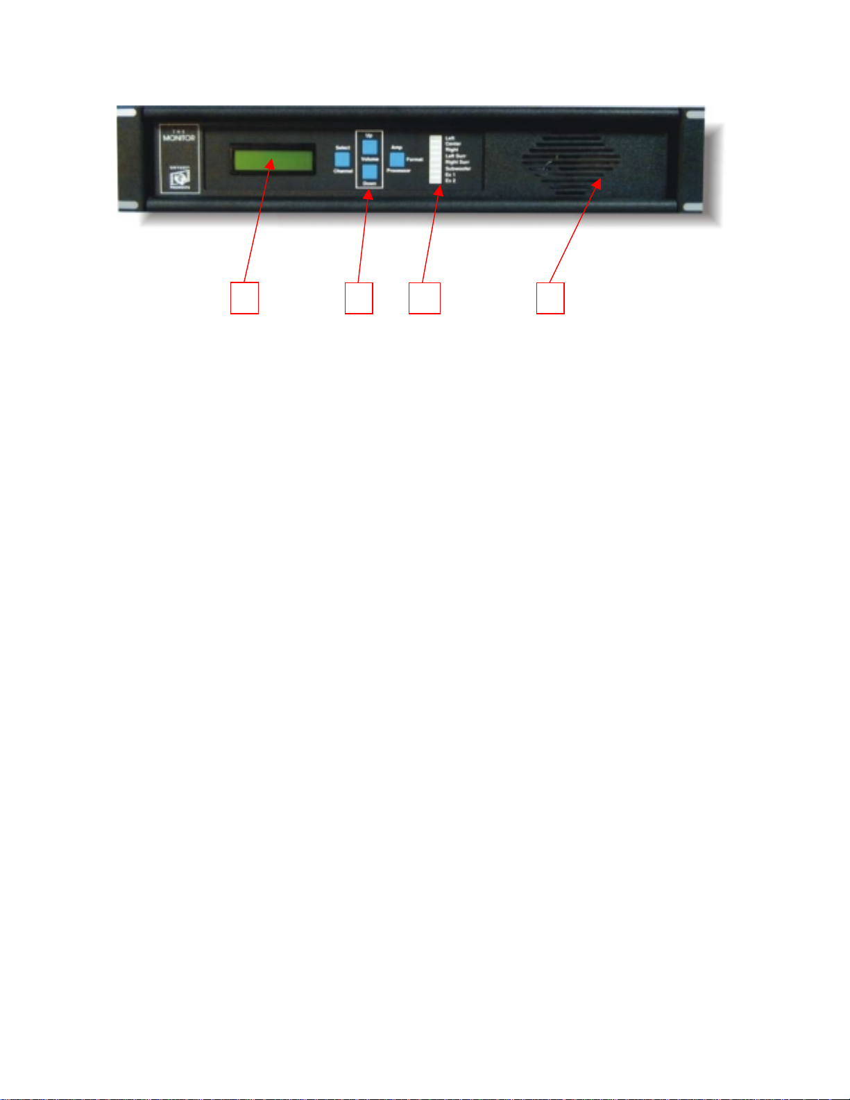
Front Panel Features
1 2 3 4
1.
LCD Screen
2.
Buttons
Select Channel – selects channel to be monitored
•
Format – select amplifier inputs or processor inputs
•
Volume Up/Down – master volume
•
3.
Signal Present Indicators
4.
Speaker
– Indicates channel selected, Amplifier or Processor, and volume level.
–
– Indicates audio information on amplifier channels
The TM-1 Monitor provides monitoring of the following channels:
L, C, R (Left Channel, Center Channel, and Right Channel)
•
External and Extra 2 – can be used to monitor Left Center and Right Center Channels, or Left EX
•
and Right EX Surround Channels.
LS, RS (Left Surround, Right Surround)
•
NOTE: The TM-2 only monitors the subwoofer signal from the amplifier and displays it only on the
signal present LED
The default mode for the TM-2 is L+C+R in processor mode.
•
The volume default is 3.0.
•
Odyssey Product s Inc.
5845 Oakbrook Parkway, Suite G / Norcross, GA 30093 / Phone: 770.825.0243 / Fax: 770.825.0245
Website: odyssey-products.com / E-mail: odysseytechnical@ mi ndspr ing.com
Page 10
Pressing the channel select button changes the channel to be monitored. After 30 seconds, if no
•
buttons are pressed the TM-2 will revert to L+C+R. Format will remain in the last mode selected
(processor or amplifier).
The Processor/Amplifier switch selects between the signals coming from the Analog Processor, and
•
the signals coming from the output of the power amplifiers.
The Volume control varies the level of the internal speaker, but does not change an input levels, or
•
the Hearing-Impaired output level.
For bi-amplified and tri-amplified sound systems: When monitoring a stage channel in amplifier
•
mode, what is monitored is a sum of the low, mid and high frequencies.
321
4
5
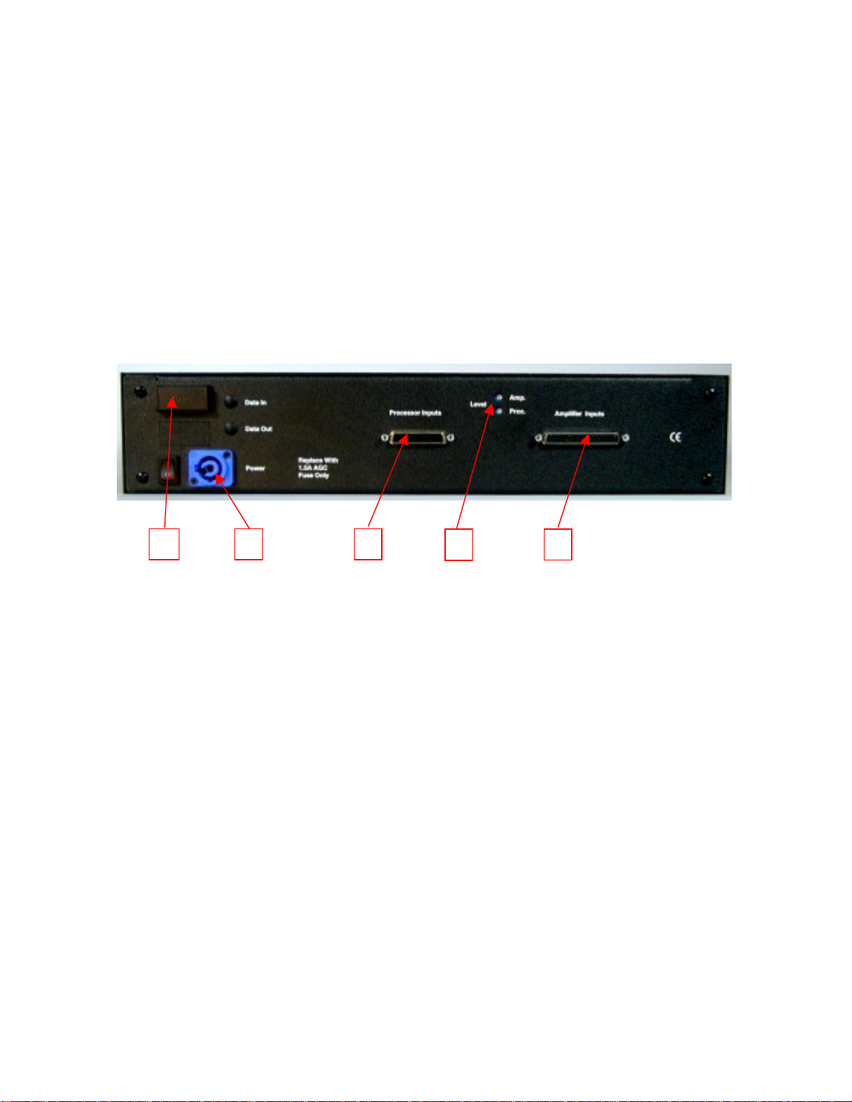
Back Panel Features
1. Fuse Holder – accepts fuses 1 ¼” X ¼” AGC fuses
2. Speakon Power Connector – Connector for the external plug-in transformer.
3. Processor Inputs Connector – DB25 female connector, accepts Odyssey Breakout Boards.
4. Input Level Adjustment Potentiometers – 1 each for processor level and amplifier level.
5. Amplifier Inputs Connector – DB37 female connector, accepts Odyssey Output 37 Card.
The external power pack is terminated with a blue Speakon connector. It is unplugged from the
TM-2 by pulling back on the metal tab and twisting the connector counter-clockwise slightly. Pull the
connector straight out of the socket. The powercon connector is plugged in by inserting it straight into
the socket, then twisting clockwise slightly until the metal tab slicks forward and locks.
Odyssey Product s Inc.
5845 Oakbrook Parkway, Suite G / Norcross, GA 30093 / Phone: 770.825.0243 / Fax: 770.825.0245
Website: odyssey-products.com / E-mail: odysseytechnical@ mi ndspr ing.com
Page 11

To remove the fuse, pull the fuse holder cover down until it unlocks. Slide the cover out like a
drawer. Remove the fuse from the clip. To close the fuse holder, push the cover in and then up slightly
until is clicks into place. The correct fuse is a 1 ¼” X ¼” AGC Normal Blow Fuse (1.5 Amps)
The processor Inputs connector is a DB25 female. It has the same pin configuration as a THX
monitor. It will accept the following Odyssey breakout cards:
Model Input 25 – wires from a passive processor are terminated to the on-board terminal strip.
•
Model Input 25/2 – same as the Input 25, but with an extra DB25 connector.
•
Model TM1-BI – sums the low and high frequencies on the stage channels from a bi-amplified
•
analog processor
It can also be hooked up directly to the Monitor Out Connector on the Sony DFP 3000 Processor.
The Amplifier Inputs connector is a DB37 female. It accepts the Odyssey Breakout Card Model
TMAMP37. Wires from the amplifier outputs are connected to the terminal strips on the TMAMP37
card.
Refer to the above pages for a complete list of the pin configurations for the DB connectors and
the breakout cards.
There are two input level control potentiometers that are accessed from the back of the TM-1.
There is one for processor levels, and one for amplifier levels. These are used to trim the two sets of
inputs until the sound levels match switching between Processor to Amplifier on the front panel.
The TM-2 Monitor also provides a Hearing-Impaired output. This output can be used to feed
hearing-impaired assisted devices. It is a fixed-level signal formed from summing Left, Center, and
Right Channels (internally). This output is not affected by the Volume Control, or by the Input Level
Adjustment Potentiometers.
Odyssey Product s Inc.
5845 Oakbrook Parkway, Suite G / Norcross, GA 30093 / Phone: 770.825.0243 / Fax: 770.825.0245
Website: odyssey-products.com / E-mail: odysseytechnical@ mi ndspr ing.com
Page 12

Warranty Information
Equipment manufactured by Odyssey Products is warranted against defects in materials and
workmanship for a one-year period from the date of shipment. There are no other ex press or
implied warranties.
Returns
During the warranty period, Odyssey will repair or replace, at its option, components which
prove defective. Equipment must be returned shipped prepaid to Odyssey. Defects caused
by modifications, misuse or accidents or shipping damage caused by inadequate packaging
for service return are not covered by this warranty. A Return Authorization Number must be
obtained from Odyssey or its agents prior to returning any products. The Return
Authorization Number must be marked on all paperwork and labels
Please send all returns to:
Odyssey Products
5845 Oakbrook Parkway, Suite G
Norcross, GA 30093
Phone 770-825-0243
Fax 770-825-0245
Odyssey Product s Inc.
5845 Oakbrook Parkway, Suite G / Norcross, GA 30093 / Phone: 770.825.0243 / Fax: 770.825.0245
Website: odyssey-products.com / E-mail: odysseytechnical@ mi ndspr ing.com
 Loading...