

Odyssey ODY-5 Owner's Manual
OWNER’ S MANUAL
TABLE OF CONTENTS:
Introduction - Pg. 1
Safety Precautions - Pg. 2
Assembly for ODY-5 - Pg. 3 - Pg. 18,
Pg.20
Cable Adjustments - Pg. 19
Cable Mapping Diagram - Pg. 21 - Pg. 24
Parts List - Pg. 25
Exploded View Diagram - Pg. 26
Adjustment Features - Pg. 29 - Pg. 31
Maintenance - Pg. 32
Optional Stations - Pg. 33
Warranty - Back Page
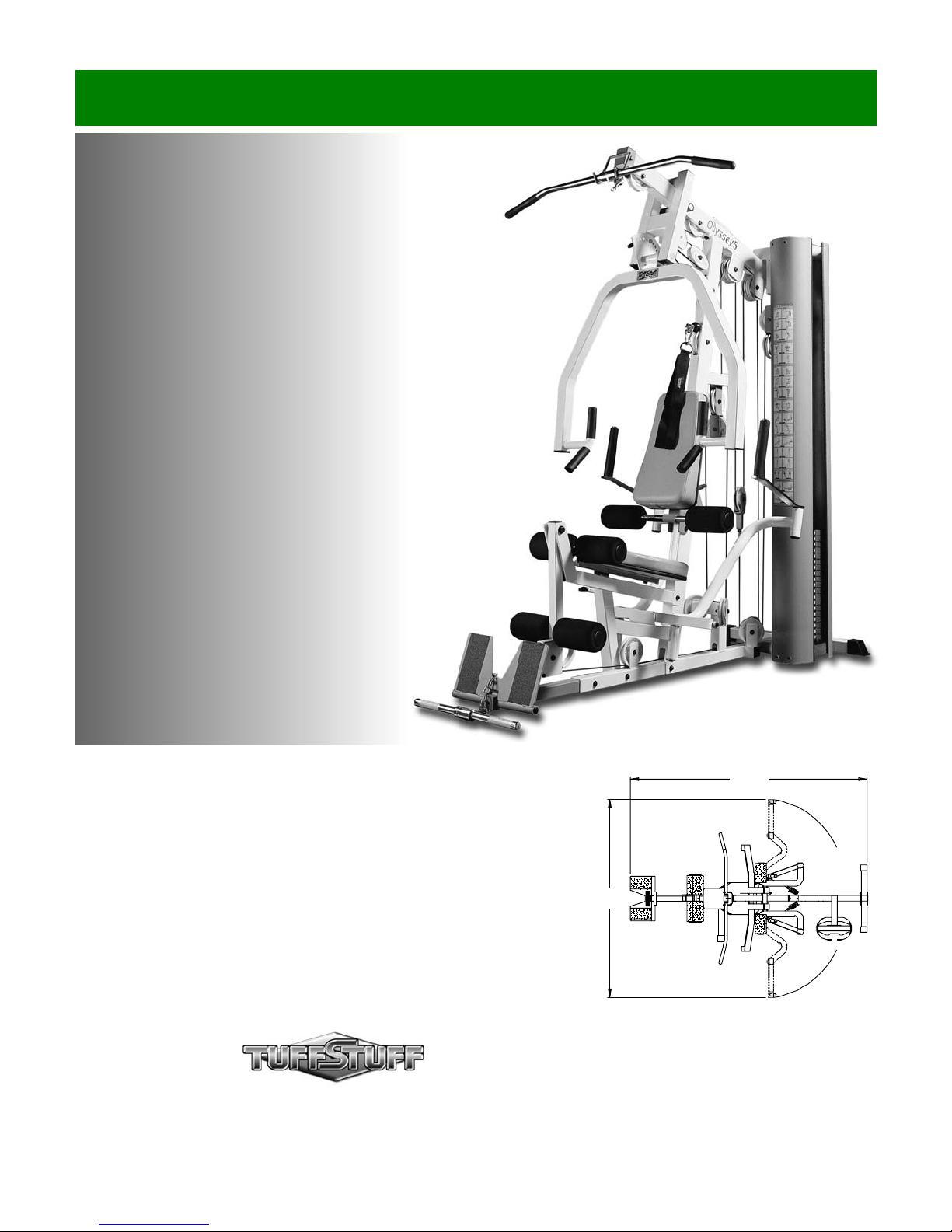
ODY-5
Odyssey Home Gym
Revision Date 05-1 0-00
85”
71”
L 85” W 71” H 83”
America’s Premium Exercise Equipment
ODY-5 Rev. 1
Introduction
About the Odyssey 5 Home Gym (ODY-5)
Congratulations on your new purchase of the Odyssey 5 Home
Gym (ODY-5). This gym is capable of a variety of different
exercises, as well as, smooth and user-friendly adjustment
features. In addition, this gym has been designed to meet the
needs and performance requirements for a suitable home exercise
machine. We hope you are completely satisfied with this product
and wish you many years of enjoyment.
Tuff Stuff Equipment
This Tuffstuff product has been built to precise quality standards
and has been carefully packaged to ensure that damage will not
occur during shipment.
indicating final inspection has been conducted by our line foreman,
is an expression of our confidence in the completeness, the
materials, and workmanship of this product.
The Home Lifetime Warranty and signature
Warranty
SEE A COPY OF WARRANTY ON BACK PAGE.
Registration Card
To avoid unnecessary delays in warranty service and to insure that
a permanent record of your purchase is on file with our factory, be
sure to complete the warranty registration card and send it to Task
Industries today.
Specifications
1. Maximum Wt. Capacity - 200 Lbs. Fixed
2. Total Machine Weight - 475 Lbs.
3. Footprint (LWH) - See Front Cover
Prior to the Assembly of the ODY-5
1. We advise you to consult your local Tuff Stuff retailer if you
should have a question or problem regarding the proper
assembly of this Odyssey 5 Home Gym (ODY-5).
2. Consider the complete surface area of the ODY-5. Use the
overhead view on the front page for designing your layout before
assembling. Once the ODY-5 has been fully assembled it will be
heavy and difficult to move, therefore you should assemble the
ODY-5 in the area where it is to be used upon completion.
3. It is recommended that another person assist you with the
assembly this unit.
4. Neatly organize and identify all parts according to the Parts List
on page 25 and the Exploded View Diagram on page 24.
Tool Requirements
1. One 9/16” combination wrench
2. One 3/4” combination wrench
3. One 7/8” combination wrench
4. Two 7/16” combination wrenches
5. One 1/2” combination wrench
6. One ratchet
7. One 9/16” socket
8. One 3/4” socket
9. One rubber mallet
10. External retaining-ring pliers
11. Windex or household glass cleaner
12. One can silicone spray/ teflon spray lubricant
13. Multi-purpose grease
14. Measuring tape
15. Masking tape
16. Utility knife
1
About the Icons
The icons displayed in this Owner’s Manual are used to facilitate
the correct assembly and safe use of this Product, as-well-as to
prevent injury to yourself or anyone else.
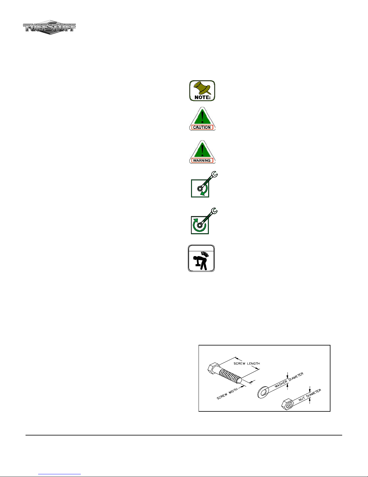
A Note provides information necessary to properly
complete a procedure or information which will make
the procedure easier to understand.
A Caution provides a special procedure or special
steps which must be taken while completing the
procedure where the Caution is found. Not following
a Caution can result in damage to the equipment.
A Warning provides a special procedure or special
steps which must be taken while completing the
procedure where the Warning is found . Not following
a Warning can result in personal injury.
Loosely Fasten provides a instruction to loosely
ex: hand tighten) a hardware assembly only.
hardware components during the assembly process.
ex: completely tighten) a hardware assembly.
LOOSELY FASTEN
FULLY FASTEN
WARNING
fasten (
This instruction is intended for the alignment of
Fully Fasten provides a instruction to fully fasten
(
This will notify you of lifting heavy components. It is
advisable to lift with your legs, not with your back, to
avoid a possible back injury.
Assembly Notes
1. Read and follow each step of this Assembly Instruction Manual in
sequence. Do not skip ahead, as it will result in an improper
assembly or in having to disassemble parts later.
2. During the assembly of this unit you will be instructed to leave
some Hex Head Cap Screws loosely fastened. Naturally, they
will be fully fastened later in the assembly process. This is done
to prevent any difficulty with alignment of some parts during this
assembly.
Hardware Measurement Diagram
Note: Due to continuing product improvements, specifications and designs are subject to change
without notice.
Even though we have prepared this manual with extreme care, neither the publisher nor the author
can accept responsibility for any errors in, or omission from, the information given.
ODY-5 Odyssey Home Gym

Safety Precautions
Safety First
Regardless of how enthusiastic you may be about getting on
your equipment and exercising, take the time to ensure that your
safety is not jeopardized. A moment’s lack of attention can result
in an accident, as can failure to observe certain simple safety
precautions.
Push Pull Pin
1/2” Special (#82)
1. Read, study and understand the Owner’s Manual and all the
warning labels on this product. Furthermore, it is
recommended to familiarize yourself and others with the
proper operation and workout recommendations for this Tuff
Stuff product prior to use. Some of this information can be
obtained in this Owner’s Manual, as well as from your local
Tuff Stuff retailer.
2. It is imperative that you retain this Owner’s Manual and be
sure all warning labels are legible and intact. Replacement
Owner’s Manuals and labels are available from your local Tuff
Stuff retailer.
3. Consult with your physician before beginning any exercise
program.
4. Use proper discretion when children are present.
5. Frayed or worn cables can be dangerous and may cause
injury. Periodically check these cables for any indication of
wear.
6. Keep hands, limbs, loose clothing and long hair well out of the
way of moving parts.
7. Do not attempt to lift more weight than you can control safely.
Push-Pull Pin 1/2”
Special (#53)
Push Pull Pin
1/2” Special (#82)
Push-Pull Pin 1/2”
Special (#53)
Push-Pull Pin
1/2” (#54)
Fig. 1 Illustration above depicts the location of the Push Pull Pins
1/2” Special (#53) and Push Pull Pin 1/2” (#54) on this unit.
Push Pull Pin
1/2” (#62)
8. Inspect the Odyssey Home Gym for any sign of wear on parts,
hardware becoming loose or cracks on welds. If a problem is
found do not use or allow the machine to be used until
defective part is repaired or replaced.
9. Pay special attention to the Push Pull Pins (#53 and #54)
located on Press Bar Selector Housing (#17), Front Upright
(#3) and Leg Extension Bench Frame (#11). See Fig.1. Be
sure they are fully engaged into the selectorized holes. Refer
to Fig. 2 for further illustration of this warning.
ODY-5 Odyssey Home Gym
Push Pull Pin
Fully Engaged
Fig. 2 Warning: Check that all Push Pull Pins 1/2” (#53, #54)
are fully engaged into the selectorized holes.
2
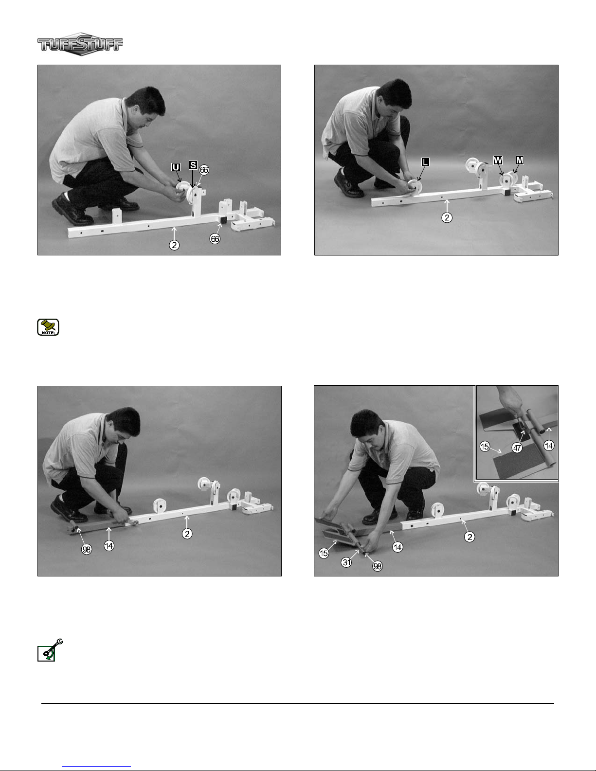
FIG. 3 On a flat surface, lay the Base Frame (#2) down and insert two
Plastic End Caps 2” Sq. (#66) into the tube-ends of the Base Frame (#2),
as labeled above. Next, attach two Nylon Pulleys 4 1/2 Rd (#64-Labeled
U, S) to the Base Frame (#2) and secure them into place using two Hex
Head Cap Screws 3/8-16 X 2 (#99), four Flat Washers SAE 3/8” (#71)
and two Nylon Insert Jam Lock Nu ts 3/8-16 (#82).
Note:The black boxed letters pointing to the pulleys are used
throughout this manual as reference to the Cable Mapping
Diagram on pages 21-24. These black boxed letters will be
primarily used for locating certain pulleys during the cable routing
process beginning with Fig. 31.
FIG. 4 Next, attach three Nylon Pulleys 4 1/2 Rd (#64-Labeled L,W,M)
to the pulley brackets on the Base Frame (#2) and secure them into place
using three Hex Head Cap Screws 3/8-16 X 1 3/4 (#93), six Flat Washers
SAE 3/8” (#71) and three Nylon Insert Jam Lock Nuts 3/8-16 (#82).
FIG. 5 Next, locate the Low Row Stabilizer (#14) and insert it into the
receptacle on the Base Frame (#2). Secure it into place using one Hex
Head Cap Screw 3/8-16 X 3 (#90), two Flat Washers SAE 3/8” (#71) and
one Nylon Insert Jam Nut 3/8-16 (#82). Next, insert two Plastic Insert
Caps 1” Rd. (#98) into the tube-ends of the Low Row Stabilizer (#14), as
labeled above.
Loosely Fasten: Do not completely fasten this hardware
assembly at this time, as it will be completely fastened later in Fig.
LOOSELY FASTEN
10 on the next page.
3
FIG. 6 Next, attach the Low Row Foot Support (#15) to the Low
Row Stabilizer (#14) and secure it into place using one Foot Roll Tube
1X16 (#31). Using the supplied Hex Key 3/16 (#108), secure the Foot
Roll Tube 1X16 (#31) into place using one Set Screw 3/8-16 X 1/2 (#47),
as shown in caption above. Be sure the Foot Roll Tube 1X16 (#31) is
flush on each end after inserted into the Low Row Foot Support (#15).
Next, insert two Plastic Insert Caps 1” Rd. (#98) into the tube-ends of the
Foot Roll Tube 1X16 (#31).
ODY-5 Odyssey Home Gym
Owner’s Manual: Assembly Instructions
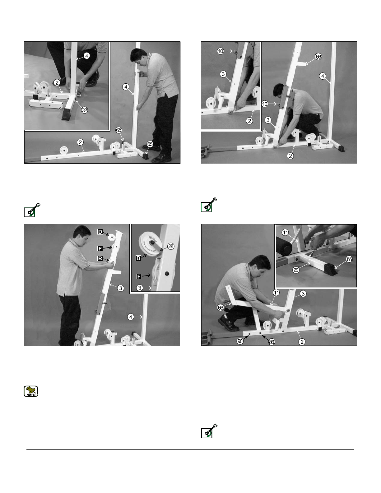
FIG. 7 Next, insert two Plastic End Caps 2” Sq. w/Groove (#65) onto
each tube-end of the Rear Upright (#4), as shown above. Next, attach
the Rear Upright (#4) to the Base Frame (#2) and secure it into place, as
shown in caption above, using one Support Plate 1/4 X 2 X 5 (#32), two
Hex Head Cap Screws 3/8-16 X 3 1/4 (#89), four Flat Washers SAE
3/8” (#71) and two Nylon Insert Lock Nuts 3/8-16 (#81).
Loosely Fasten: Do not completely fasten this hardware
assembly at this time, as it will be completely fastened later in the
LOOSELY FASTEN
assembly process.
FIG. 8 Next, attach the Front Upright (#3) to the Base Frame (#2) , in
the position as shown above, and secure it into place using one Hex
Head Cap Screw 3/8-16 X 2 3/4 (#91), two Flat Washers SAE 3/8” (#71)
and one Nylon Insert Jam Lock Nut 3/8-16 (#82). Next, insert one Plastic
Insert Cap 2” Sq. (#66) into the tube-end of the Front Upright (#3).
Loosely Fasten: Do not completely fasten this hardware
assembly at this time, as it will be completely fastened later in the
LOOSELY FASTEN
assembly process.
FIG. 9 Next, attach a Nylon Pulley 4 1/2 Rd. (#64- Labeled D) to the
pulley plate located on the Front Upright (#3) and secure it into place
using one Cable Retainer Bracket L-Shaped (#28), one Hex Head Cap
Screw 3/8-16 X 1 3/4 (#93), two Flat Washers SAE 3/8” (#71) and one
Nylon Insert Jam Lock Nut 3/8-16 (#82). Refer to the Exploded View
Diagram on page 26 for further illustration of this assembly.
Note: Be sure to position the Cable Retainer Bracket L- Shaped
(#28) as shown in caption above.
Next, attach two Nylon Pulleys 4 1/2 Rd. (#64-Labeled F,R) into the pulley
brackets located on the Front Upright (#3) and secure them into place
using two Hex Head Cap Screws 3/8-16 X 2 1/2 (#92), four Flat Washers
SAE 3/8” (#71) and two Nylon Insert Jam Lock Nuts 3/8-16 (#82).
ODY-5 Odyssey Home Gym
FIG. 10 Next, locate the Leg Extension Bench Frame (#11) and
secure it to the Front Upright (#3) , as shown above, using one Hex Head
Cap Screw 3/8-16 X 2 3/4 (#91), two Flat Washers SAE 3/8” (#71) and
one Nylon Insert Jam Lock Nut 3/8-16 (#82). Locate the Stabilizer
14” (#29) and insert one Plastic End Cap 2” Sq. w/Groove (#65) into the
tube-end. Secure the other end of the LegExtension Bench Frame
(#11) to the Base Frame (#2) and the Stabilizer 14” (#29) using one Hex
Head Cap Screws 3/8-16 X 5 (#86), two Flat Washers SAE 3/8” (#71) and
one Nylon Insert Lock Nut 3/8-16 (#81). Next, secure the other end of the
Stabilizer 14” (#29) to the Base Frame (#2) using one Hex Head Cap
Screw 3/8-16 X 3 (#90), two Flat Washers SAE 3/8” (#71) and one Nylon
Insert Lock Nut 3/8- 16 (#81). Next, insert one Plastic Insert Cap 2” Sq.
(#66) into the tube-end of the Leg Extension Bench Frame (#11).
Loosely Fasten: Do not completely fasten this hardware
assembly at this time, as it will be completely fastened later in the
LOOSELY FASTEN
assembly process.
4

FIG. 11 Next, attach the Leg Extension Arm (#12) , in the position as
shown, to the Leg Extension Bench Frame (#11) and secure it into
place using one Leg Extension Axle 1/2 X 2 1/2 (#9) . Next, secure the
Leg Extension Axle 1/2 X 2 1/2 (#9) into place using two Set Screws
1/4-20 X 3/8 (#48), as shown in caption above. Use the supplied Hex Key
Long 1/8 (#109) for fastening these Set Screws 1/4-20 X 3/8 (#48). Next,
insert one Plastic Insert Cap 1 1/2 Sq. (#67) into the tube-end of the Leg
Extension Arm (#12).
Note: It is recommended to grease the Leg Extension Axle 1/2 X
2 1/2 (#9) with multi-purpose grease prior to assembling.
FIG. 12 Attach the Top Pulley Assembly (#5) , in the position as
shown, to the Front Upright (#3) and secure it into place using two Hex
Head Cap Screws 3/8-16 X 4 1/4 (#88), four Flat Washers SAE 3/8” (#71)
and two Nylon Insert Lock Nuts 3/8-16 (#81).
Loosely Fasten: Do not completely fasten this hardware
assembly at this time, as it will be completely fastened later in the
LOOSELY FASTEN
assembly process.
FIG. 13 Next, attach the Top Pulley Assembly (#5) to the Rear
Upright (#4) and secure it into place using two Hex Head Cap Screws
3/8-16 X 3 1/4 (#89), four Flat Washers SAE 3/8” (#71) and two Nylon
Insert Lock Nut 3/8-16 (#81). Next, insert one Plastic Insert Cap 2” Sq.
(#66) into the tube-end on the Rear Upright (#4).
Fully Fasten: Proceed to align and fully fasten this hardware assembly and all the previous assemblies that were left loosely fas-
tened.
FULLY FASTEN
5
FIG. 14 Next, attach two Nylon Pulleys 4 1/2 Rd. (#64-Labeled A,B)
into the pulley brackets located on the Top Pulley Assembly (#5) and
secure them into place using two Hex Head Cap Screws 3/8-16 X 2 1/2
(#92), four Flat Washers SAE 3/8” (#71) and two Nylon Insert Jam Lock
Nuts 3/8-16 (#82). Next, attach four Nylon Pulleys 4 1/2 Rd. (#64Labeled P,G,N,H) into the pulley brackets located on the Top Pulley
Assembly (#5) and secure them into place using two Hex Head Cap
Screws 3/8-16 X 2 3/4 (#91), four Flat Washers SAE 3/8” (#71) and two
Nylon Insert Jam Lock Nuts 3/8-16 (#82).
ODY-5 Odyssey Home Gym
Owner’s Manual: Assembly Instructions
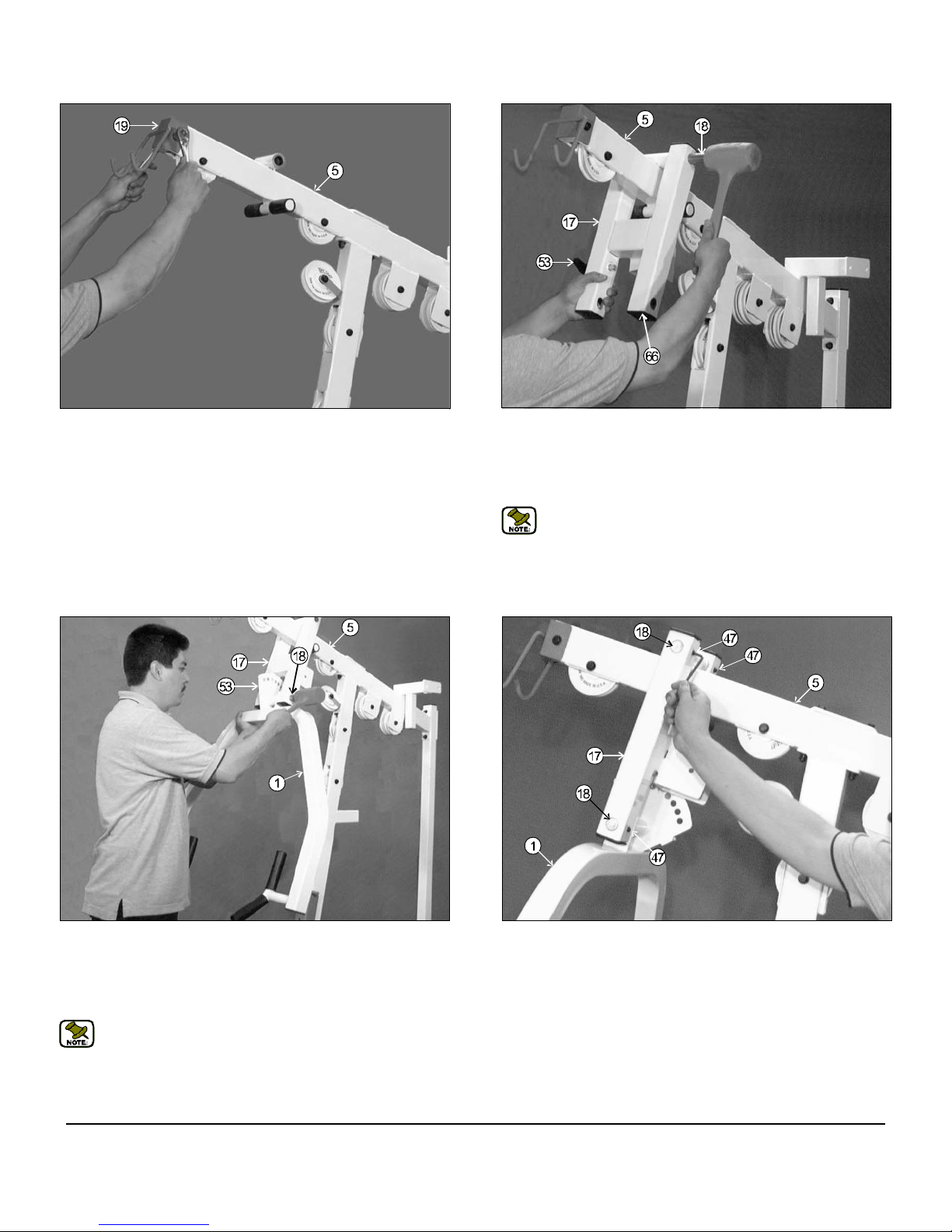
FIG. 15 Next, attach Lat Bar Holder 2 X 3 (#19), in the position as
shown above, to the Top Pulley Assembly (#5) and secure it into place
using one Hex Head Cap Screw 3/8-16 X 2 3/4 (#91), two Flat Washers
SAE 3/8” (#71) and one Nylon Insert Jam Lock Nut 3/8-16 (#82).
FIG. 16 Attach the Press Bar Selector Housing (#17) to the Top
Pulley Assembly (#5), as shown above. Using a rubber mallet, insert
the Pivot Axle 1 X 8 1/8 (#18) through the holes in the Press Bar
Selector Housing (#17) and through the receptacle on the Top Pulley
Housing (#5) until it is flush with both sides. Refer to Fig. 67 on page 27
for further clarification of this assemb ly.
Note: It is recommended to grease the Pivot Axle 1 X 8 1/8 (#18)
with multi-purpose grease prior to assembling. Also, the four
Plastic Insert Caps 2” Sq. (#66) located in the tube-ends of
the Press Bar Selector Housing (#17) have been pre-assembled
by the factory.
FIG. 17 Next, insert the Press Bar (#1) up into the Press Bar
Selector Housing (#17) and support in into place using the push-pull pin
(#53-Not Shown). Next, using a rubber mallet, insert the Pivot Axle 1 X 8
1/8 (#18) into the Press Bar Selector Housing (#17) and through the
Press Bar (#1).Refer to Fig. 67 on page 27 for further clarification of this
assembly.
Note: It is recommended to grease the Pivot Axle 1 X 8 1/8 (#18)
with multi-purpose grease prior to assembling.
ODY-5 Odyssey Home Gym
FIG. 18 Next, secure the Press Bar Selector Housing (#17) to the
Pivot Axle 1 X 8 1/8 (#18) using two Set Screws 3/8-16 X 1/2 (#47), as
shown above. Then, secure into place the Press Bar (#1) to the Pivot
Axle 1 X 8 1/8 (#18) using two Set Screws 3/8-16 X 1/2 (#47). Use the
Supplied Hex Key 3/16 (#108) for securing all four Set Screws 3/8-16 X
1/2 (#108) into the threaded sockets on the Press Bar Selector Housing
(#17). Next, apply four 1” Rd. Silver Mylar Decals (#111–Not shown) over
the ends of the Pivot Axles 1 X 8 1/8 (#18). These decals are used to
hide and protect the ends of axles.
6

FIG. 19 Next, attach two Nylon Pulleys 4 1/2 Rd. (#64-Labeled C,E) to
the pulley bracket located on the Press Bar Selector Housing (#17) and
secure them into place using one Hex Head Cap Screw 3/8-16 X 2 3/4
(#91), two Flat Washers SAE 3/8” (#71) and one Nylon Insert Jam Lock
Nut 3/8-16 (#82).
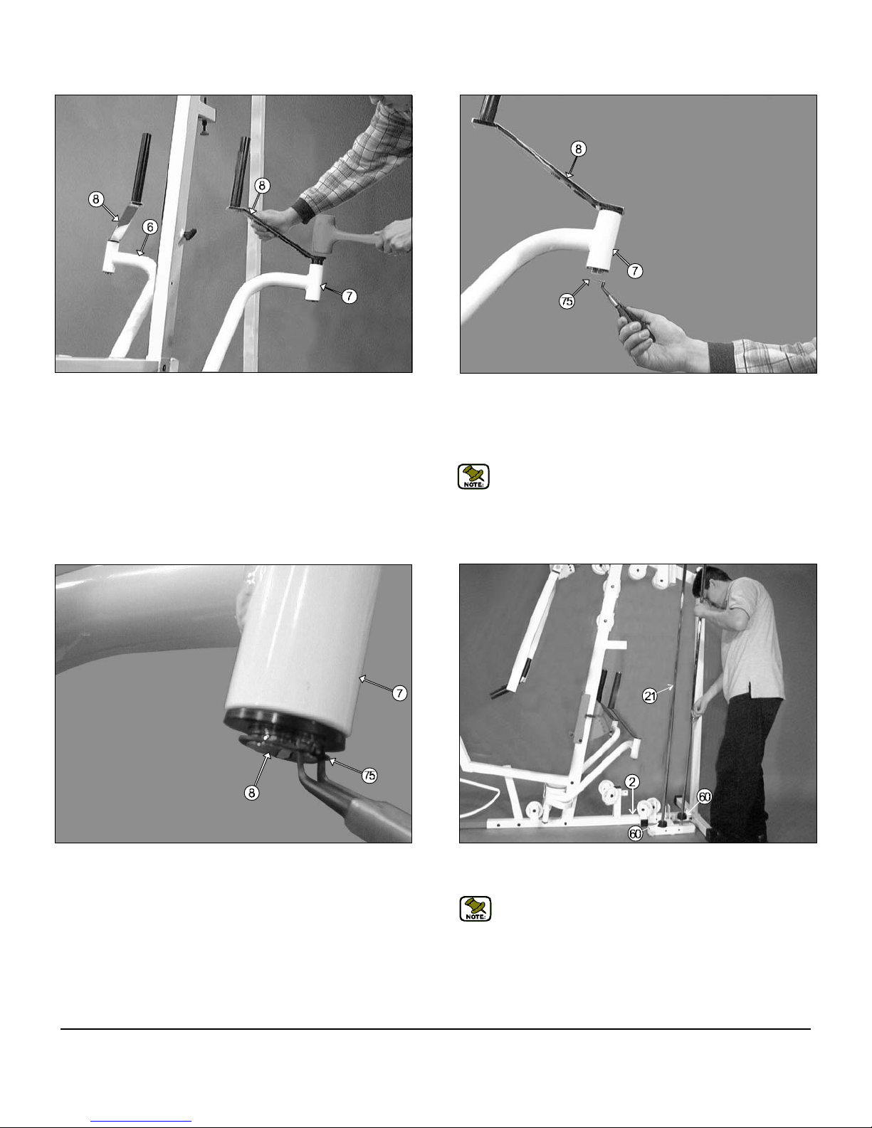
FIG. 20 Next, insert the Left Pec Dec Arm (#7) , in the position as
shown above, into the receptacle on the Front Upright (#3). Repeat the
same procedure for the Right Pec Dec Arm (#6) . Refer to Fig. 72 on
page 28 or the Exploded View Diagram on page 26 for further illustration
of this assembly.
Note: It is recommended to grease both axles on the Left and
Right Pec Dec Arms (#7,#6) with multi-purpose grease prior to
assembling.
FIG. 21 Secure the Left Pec Dec Arm (#7) into place using one Hex
Head Cap Screw 3/8-16 X 1 (#95), one Split Washer 3/8” (#76) and one
Fender Washer 3/8 X 1 1/2 (#72). Repeat the same procedure for the
Right Pec Dec Arm (#6). Refer to the Exploded View Diagram on page
26 for further illustration of this assembly.
7
FIG. 22 Locate the two Pec Dec Swivel Handles (#8) and organize
them on a flat surface, as shown above.
Note: Parts (#47, #50 and #59) have been pre-assembled on the
Pec Dec Swivel Handles (#8) by the factory.
ODY-5 Odyssey Home Gym
Owner’s Manual: Assembly Instructions
FIG. 23 Next, using a rubber mallet, insert a Pec Dec Swivel Handle
(#8), in the position as shown above, into the Left Pec Dec Arm (#7). Be
sure that the Pec Dec Swivel Handle (#8) has been completely inserted
through the receptacle on the Left Pec Dec Arm (#7). Repeat the same
procedure for the Right Pec Dec Arm (#6).Refer to Fig. 72 on page 28
for further illustration of this assembly.
FIG. 24 Next, secure the Pec Dec Swivel Handles (#8) using two Retaining Snap Rings (#75). If possible, use special snap ring pliers for this
job, as shown above. If the tool is not available, carefully work each Retaining Snap Ring (#75) into the groove, then push up alternately with a
screw driver working the Retaining Snap Ring (#75) into the groove.
Refer to Fig. 72 on page 28 for further illustration of this assembly.
Note: Be careful not to distort the Retaining Snap Rings (#75) or
bend them.
FIG. 25 Picture of Retaining Snap Ring (#75) inserting into Pec Dec
Swivel Handle (#8).
ODY-5 Odyssey Home Gym
FIG. 26 Insert the two Guide Rods 3/4 X 72 (#21) into the receptacles
on the Base Frame (#2), as shown above. Next, insert two Rubber
Donuts 3/4 X 2 1/2 (#60) onto each Guide Rod 3/4 X 72 (#21) .
Note: Lubricate the Guide Rods 3/4 X 72 (#21) with a silcone or
teflon lubricant at this time.
8
Update: The Weight Stack pictured in this manual differ in shape and appearance to the supplied with this unit.
Update: The Weight Stack pictured in this manual differ in shape and appearance to the supplied with this unit.
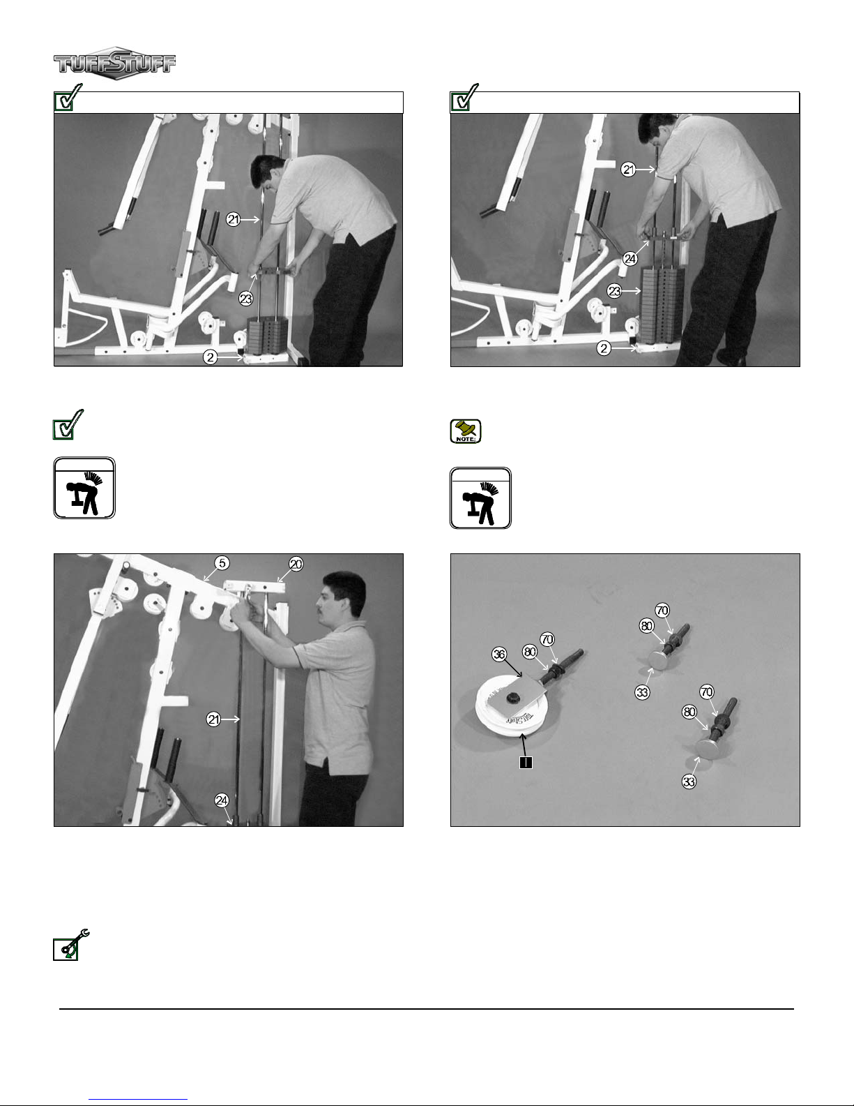
FIG. 27 Carefully begin sliding the Weight Plates over the Guide
Rods 3/4 X 72 (#21), one or two at a time as your skill permits.
Updated: The Weight Stack has been replaced by the Weight
Stack illustrated on Fig. 73. Refer to Fig. 73 on page 28 to com-
plete this assembly.
UPDATED
WARNING
Warning: Do not lift more than you can control safely. In
addition, do not lift using only your back. It is recommended
that when you are lifting, bend your knees and lift slowly with
your back straight. Be sure that the weight is distributed
over your knees or legs when lifting. Also, it is advisable to
wear a well fitted lifting belt during heavy lifting.
FIG. 28 Now slide the Top Plate/Selector Bar (#24) over the Guide
Rods 3/4 X 72 (#21) allowing it to come to rest on the completed weight
stack.
Note: Be sure the label (FRONT SIDE) located on the Top Plate/
Selector Bar (#24) is facing toward you before you slide the Top
Plate/Selector Bar (#24) over the Guide Rods 3/4 X 72 (#21) .
WARNING
Warning: Do not lift more than you can control safely. In
addition, do not lift using only your back. It is recommended
that when you are lifting, bend your knees and lift slowly with
your back straight. Be sure that the weight is distributed
over your knees or legs when lifting. Also, it is advisable to
wear a well fitted lifting belt during heavy lifting.
FIG. 29 Maneuver the two Guide Rods 3/4 X 72 (#21) into the holes
on the bottom side of the Guide Rod Retainer Housing (#20) .Next,
mount the Guide Rod Retainer Housing (#20) along with the two captive
Guide Rods 3/4 X 72 (#21) to the side of the Top Pulley Assembly (#5) .
Secure this assembly using two Hex Head Cap Screws 3/8-16 X 2 3/4
(#91), four Flat Washer SAE 3/8” (#71) and two Nylon Insert Jam Lock
Nuts 3/8-16 (#82).
Loosely Fasten: Do not completely fasten this hardware
assembly at this time, as it will be completely fastened later in the
LOOSELY FASTEN
assembly process.
9
FIG. 30 First, locate the Adjustable Pulley Bracket (#36) and insert
one Nylon Pulley 4 1/2 Rd. (#64-Labeled I). Secure the Nylon Pulley 4
1/2 Rd. (#64-Labeled I) into place using one Hex Head Cap Screws 3/816 X 1 3/4 (#93), two Flat Washers SAE 3/8” (#71) and one Nylon Insert
Jam Lock Nut 3/8-16 (#82). Next, thread one Regular Hex Nut 1/2-13
(#80) and insert one Flat Washer SAE 1/2” (#70) over the bolt on the
Adjustable Pulley Bracket (#36), as shown above at the left. Second,
locate the two Adjustable Stoppers (#33) and thread one Regular Hex
Nut 1/2-13 (#80) and insert one Flat Washer SAE 1/2” (#70) over each
bolts, as shown above at the middle and right.
ODY-5 Odyssey Home Gym
Owner’s Manual: Assembly Instructions
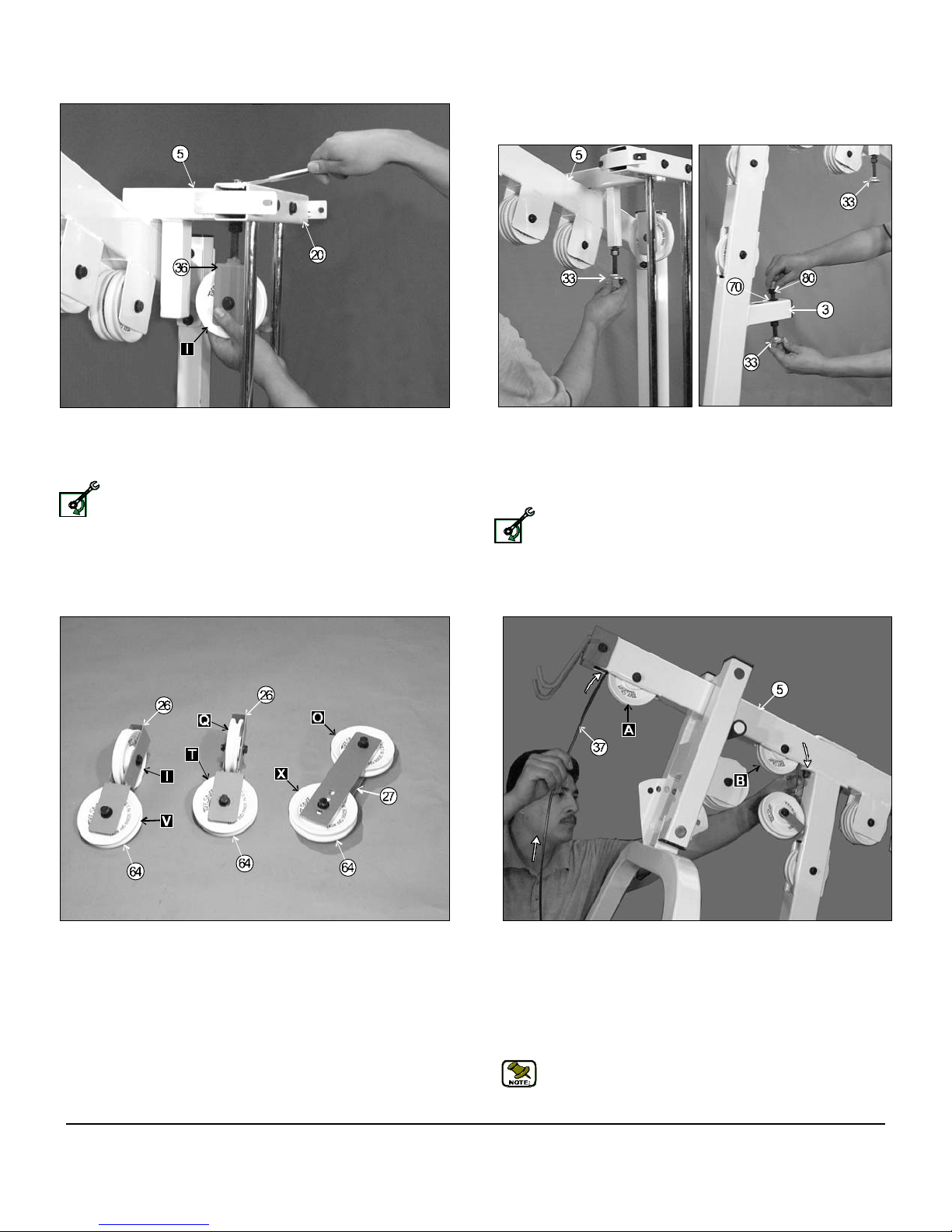
FIG. 31 Attach the Adjustable Pulley Bracket (#36) through the hole
on the Top Pulley Assembly (#5) and secure it into place at the top
using one Flat Washer SAE 1/2” (#70) and one Nylon Insert Lock Nut 1/213 (#79).
Loosely Fasten: Do not completely fasten this hardware
assembly at this time, as it will be completely fastened later in the
LOOSELY FASTEN
assembly process.
FIG. 32 Next, thread a Adjustable Stopper (#33) into the threaded
socket located on the Top Pulley Housing (#5) , as shown in left picture
above. Next, insert another Adjustable Stopper (#33) into the receptacle
located on the Front Upright (#3) and secure it into place using one Flat
Washer SAE 1/2" (#70) and one Regular Nut 1/2-13 (#80), as shown in
right picture above.
Loosely Fasten: Do not completely fasten this hardware assembly
at this time, as it will be completely fastened later in the assembly
LOOSELY FASTEN
process.
FIG. 33 Locate the two Closed-End Double Pulley Brackets (#26)
and attach four Nylon Pulleys 4 1/2 Rd. (#64-Labeled I,V,Q,T). Secure
them into place using four Hex Head Cap Screws 3/8-16 X 1 3/4 (#93),
eight Flat Washers SAE 3/8” (#71) and four Nylon Insert Jam Lock Nuts
3/8-16 (#82). Next, locate the two Adjustable Double Pulley Plates
(#27), as shown above at the right, and attach two Nylon Pulleys 4 1/2
Rd. (#64-Labeled O,X). Secure the pulleys into place using two Hex
Head Cap Screws 3/8-16 X 1 3/4 (#93), four Flat Washers SAE 3/8” (#71)
and two Nylon Insert Jam Lock Nuts 3/8-16 (#82).
ODY-5 Odyssey Home Gym
FIG. 34 Begin routing the Lat Cable (#37). First, remove the Nylon
Pulley 4 1/2 Rd. (#64- Labeled B). Then, route the end of the Lat Cable
(#37) up and over the Nylon Pulley 4 1/2 Rd. (#68- Labeled A), then
through the tube of the Top Pulley Assembly (#5). Then, pull the Lat
Cable (#37) down where the Nylon Pulley 4 1/2 Rd. (#64- Labeled B) was
once attached. Next, using the same hardware, re-attach the Nylon
Pulley 4 1/2 Rd. (#64- Labeled B) with the Lat Cable (#37) to the Top
Pulley Assembly (#5).Be sure the Lat Cable (#37) is routed properly
into the groove on the Nylon Pulley 4 1/2 Rd. (#64- Labeled B).
Note: Refer to the Cable Mapping Diagram on page 21 for further
detailed illustration of the Lat Cable (#37) routing.
10
 Loading...