

Page 1
P A R T N E R I N G I N E S T H E T I C D I G I T A L D E N T I S T R Y
M
S
O D Y S S E Y
Navigator
3 W AT T D I O D E L A S E R
Owners Manual
®
TM
Page 2

TABLE OF CONTENTS
Section 1
Introduction. . . . . . . . . . . . . . . . . . . . . . . . . . . . . . . . . . . . . . . . . . . . . 5
Section 2
Specifications. . . . . . . . . . . . . . . . . . . . . . . . . . . . . . . . . . . . . . . . . . . . 6
2.0 Specifications . . . . . . . . . . . . . . . . . . . . . . . . . . . . . . . . . . . . . . . . . . . . . . . . . . . . . . . . . . . 6
2.1 Delivery System Specifications . . . . . . . . . . . . . . . . . . . . . . . . . . . . . . . . . . . . . . . . . . . . . 6
2.2 Warranty (also see section 8). . . . . . . . . . . . . . . . . . . . . . . . . . . . . . . . . . . . . . . . . . . . . . . 7
2.3 Parts List. . . . . . . . . . . . . . . . . . . . . . . . . . . . . . . . . . . . . . . . . . . . . . . . . . . . . . . . . . . . . . . 7
Section 3
Laser Assembly Instructions. . . . . . . . . . . . . . . . . . . . . . . . . . . . . . . . 8
3.0 Removing the Laser from the Packaging. . . . . . . . . . . . . . . . . . . . . . . . . . . . . . . . . . . . . . 8
3.0.1 Instructions on Unpacking & Dealer Assistance ............................................................................8
3.0.2 Shipping Container Information ..................................................................................................8
3.0.3 Contents of Shipping Container...................................................................................................8
3.1 Procedure for Proper Laser Assembly . . . . . . . . . . . . . . . . . . . . . . . . . . . . . . . . . . . . . . . . 8
3.1.1 Wireless Foot Pedal Installation Procedure....................................................................................9
3.1.2 Power Cord Installation .............................................................................................................10
3.1.3 Direct Power Supply ..................................................................................................................10
3.1.4 Installing the handpiece cable to the laser .................................................................................11
3.1.5 Inserting the unit-dose laser tip into the handpiece....................................................................12
3.1.6 Placing the laser unit in the docking cradle................................................................................13
3.1.7 Odyssey Navigator Remote Interlock ..........................................................................................13
3.1.8 Emergency Shutdown Switch ....................................................................................................14
3.1.9 Powering up the Laser ...............................................................................................................14
3.1.10 Enter the digital key ...................................................................................................................14
3.1.11 Installation Test ..........................................................................................................................15
3.1.12 Check of the Emergency Shutdown System ...............................................................................15
3.1.13 Touch Screen Menu ..................................................................................................................16
3.1.14 Preset Programs .........................................................................................................................18
3.2 Evaluating the Facility and Environmental Considerations . . . . . . . . . . . . . . . . . . . . . . 19
3.2.1 Power Requirements ..................................................................................................................19
3.2.2 Heating and Ventilation .............................................................................................................19
3.2.3 Transport and Storage................................................................................................................19
3.2.4 Lighting .....................................................................................................................................19
3.2.5 Combustible Chemicals and Gases.............................................................................................19
3.2.6 High Speed Vacuum Systems .....................................................................................................19
3.2.7 Access and Visual ......................................................................................................................19
3.2.8 Odyssey Navigator Diode Laser Frequency .................................................................................20
2
T h e L e a d e r i n D i o d e L a s e r s .
Page 3

TABLE OF CONTENTS
Section 4
Safety Considerations. . . . . . . . . . . . . . . . . . . . . . . . . . . . . . . . . . . . 21
4.1 Laser Safety Program. . . . . . . . . . . . . . . . . . . . . . . . . . . . . . . . . . . . . . . . . . . . . . . . . . . . 21
4.2 Continuing Education. . . . . . . . . . . . . . . . . . . . . . . . . . . . . . . . . . . . . . . . . . . . . . . . . . . . 21
4.3 In-Office Safety Issues . . . . . . . . . . . . . . . . . . . . . . . . . . . . . . . . . . . . . . . . . . . . . . . . . . . 22
4.3.1 Lighting ....................................................................................................................................22
4.3.2 Combustible chemicals or gases ...............................................................................................22
4.3.3 Safety Eyewear ........................................................................................................................22
4.3.4 Test Firing the Laser ..................................................................................................................22
4.3.5 Power Changes With Fiber Changes .........................................................................................22
4.3.6 Danger - Laser In Use Signage ..................................................................................................22
4.3.7 Sharps Disposal and Sponge Removal .......................................................................................22
4.3.8 Plume Evacuation .....................................................................................................................22
4.3.9 Laser Security ............................................................................................................................22
4.3.10 Emergency Shutdown Options ..................................................................................................23
4.3.11 Hard Tissue Procedures .............................................................................................................23
Section 5
Operating the Laser . . . . . . . . . . . . . . . . . . . . . . . . . . . . . . . . . . . . . 24
5.0 Intended Uses. . . . . . . . . . . . . . . . . . . . . . . . . . . . . . . . . . . . . . . . . . . . . . . . . . . . . . . . . . 24
5.1 Standby and Ready Status. . . . . . . . . . . . . . . . . . . . . . . . . . . . . . . . . . . . . . . . . . . . . . . . 24
5.2 Continuous or Pulse Mode. . . . . . . . . . . . . . . . . . . . . . . . . . . . . . . . . . . . . . . . . . . . . . . . 24
5.2.1 Continuous Wave (CW) Mode ...................................................................................................24
5.2.2 Pulsed Energy Mode ..................................................................................................................24
5.3 Tissue Responses to Laser Energy . . . . . . . . . . . . . . . . . . . . . . . . . . . . . . . . . . . . . . . . . . 25
5.4 Systems Procedures . . . . . . . . . . . . . . . . . . . . . . . . . . . . . . . . . . . . . . . . . . . . . . . . . . . . . 25
5.4.1 Treatment Area Requirements ....................................................................................................25
5.4.2 Foot Pedal..................................................................................................................................25
5.4.3 Unit-dose Fiber Tip ..................................................................................................................25
5.4.4 Fiber Preparation........................................................................................................................25
5.4.5 Emergency Shut Off Button .....................................................................................................25
5.4.6 Digital Key ................................................................................................................................25
5.4.7 Setting Parameters for the Quick Set Mode ..............................................................................25
5.4.8 Select Your Power .....................................................................................................................26
5.4.9 Selecting Programs ....................................................................................................................26
5.4.10 Aiming Beam ............................................................................................................................26
5.4.11 Tips............................................................................................................................................26
5.4.12 Procedure ..................................................................................................................................26
5.4.13 Odyssey Navigator Self Diagnostic and Monitoring.....................................................................27
O D Y S S E Y
Navigator
3 W A T T D I O D E L A S E R
®
TM
3
Page 4

TABLE OF CONTENTS
Section 6
System Components: Preparations, Care and Maintenance . . . . . 28
6.0 Unit Dose Fiber Tips . . . . . . . . . . . . . . . . . . . . . . . . . . . . . . . . . . . . . . . . . . . . . . . . . . . . . 28
6.0.1 General......................................................................................................................................28
6.0.2 Replacing a Unit Dose Fiber Tip .................................................................................................28
6.1 Fiber Preparation . . . . . . . . . . . . . . . . . . . . . . . . . . . . . . . . . . . . . . . . . . . . . . . . . . . . . . . 28
6.1.1 Quartz/Silica Fiber .....................................................................................................................28
6.1.2 Cleaving the Fiber .....................................................................................................................29
6.1.3 Initiating the Fiber .....................................................................................................................29
6.2 Laser Maintenance. . . . . . . . . . . . . . . . . . . . . . . . . . . . . . . . . . . . . . . . . . . . . . . . . . . . . . 29
6.2.1 Laser Chassis Disinfection ..........................................................................................................29
6.2.2 LCD Display ..............................................................................................................................29
6.2.3 Calibration.................................................................................................................................30
6.2.4 Battery Useful life ......................................................................................................................30
6.3 Handpiece Sterilization . . . . . . . . . . . . . . . . . . . . . . . . . . . . . . . . . . . . . . . . . . . . . . . . . . 30
6.3.1 Handpiece Components.............................................................................................................30
6.3.2 Recommended Autoclave Procedure ..........................................................................................31
6.3.3 Prepare Fiber .............................................................................................................................32
6.3.4 Mounting the Tip .....................................................................................................................32
Section 7
Labels, Signs, Warnings and Manufacturer’s Information. . . . . . . 33
7.1 Regulatory Compliance . . . . . . . . . . . . . . . . . . . . . . . . . . . . . . . . . . . . . . . . . . . . . . . . . . 33
7.2 Labels . . . . . . . . . . . . . . . . . . . . . . . . . . . . . . . . . . . . . . . . . . . . . . . . . . . . . . . . . . . . . . . . 33
7.2.1 Danger Laser in Use ...................................................................................................................33
7.2.2 Class 4 Laser Product ................................................................................................................33
7.2.3 Aiming Beam laser.....................................................................................................................33
7.2.4 Interference with wireless signal.................................................................................................33
7.3 Device Cautions . . . . . . . . . . . . . . . . . . . . . . . . . . . . . . . . . . . . . . . . . . . . . . . . . . . . . . . . 33
7.4 Nominal Ocular Hazard Distance (NOHD) . . . . . . . . . . . . . . . . . . . . . . . . . . . . . . . . . . . . 34
Section 8
Servicing . . . . . . . . . . . . . . . . . . . . . . . . . . . . . . . . . . . . . . . . . . . . . . 35
8.1 Warranty Policy . . . . . . . . . . . . . . . . . . . . . . . . . . . . . . . . . . . . . . . . . . . . . . . . . . . . . . . . 35
8.2 Repairs & Returns to Ivoclar Vivadent, Inc. . . . . . . . . . . . . . . . . . . . . . . . . . . . . . . . . . . . 35
Section 9
Selected References on Laser Dentistry . . . . . . . . . . . . . . . . . . . . . 36
Section 10
Troubleshooting . . . . . . . . . . . . . . . . . . . . . . . . . . . . . . . . . . . . . . . . 37
4
T h e L e a d e r i n D i o d e L a s e r s .
Page 5

Section 1
INTRODUCTION
s dentists strive to create the perfect smile, they are often compromised by the technology they use in their practice.
A
Respected leaders from the dental profession and dental equipment manufacturers have sought to identify the most practical
and least invasive technology available to deliver restorative and preventive care. Today, thanks to continuing efforts by these
industry leaders, we have seen the introduction of many new devices that have advanced the dental professional’s ability to
erform at the highest standards.
p
®
The ODYSSEY
available for soft tissue modification and preventative care; now featuring wireless power control. Unlike solid state lasers
that utilize a man-made rod of elements such as yttrium, aluminum, and garnet, doped with a rare earth compound like
Erbium, the diode has components that have become known for their durability, dependability and longevity. We are, of
course, referring to semi-conductor crystal technology like that found in televisions, DVD players, telephones and many more
household products that we have learned to rely on each day. The major components of the ODYSSEY NAVIGATOR are semiconductor “chips” made from Aluminum, Gallium and Arsenide, together commonly referred to as AlGaAs. They are activated or “pumped” by passing an electrical current through the diode to produce an elliptical shaped display of monochromatic
light that can be focused into a very small point and placed into the delivery fiber.
The wavelength produced by the diode is approximately 810 nanometers (nm) and produces invisible non-ionizing thermal
radiation that does not create changes in cellular DNA. The diode is air cooled and highly efficient when used correctly. For
safety, the diode features several ways to stop energy flow if the operator wishes to deactivate the laser. The safety system
includes a choice of an emergency shutoff switch, a power switch, a power cord or an electrical plug. Any of these items
can be used to shut down the laser. The design and technology used in the ODYSSEY NAVIGATOR allows the dentist or
hygienist* to transport the laser between different operatories. It has a lightweight and durable chassis that is designed to
use 110 – 120 V electricity found in most dental offices.
NAVIGATOR™DIODE LASER from Ivoclar Vivadent, Inc. represents the latest solid state diode laser technology
Training is recommended and opportunities for such are available through such outlets as Ivoclar Vivadent, Inc. Please visit
our web site for training dates and locations at www.getodysseylaser.com. In addition, The Academy of Laser Dentistry,
dental schools and many dental continuums offer suitable courses. You may also ask your authorized dealer representative
for the names of dental professionals in your area who have a laser and who could help you in a mentoring capacity. Laser
safety is paramount in importance and each office should quickly develop and implement a laser safety program and appoint
a “laser safety officer” to be responsible for the laser. Their duties include management of the laser and all accessories as
well as training office personnel in all aspects of laser safety. There are many applications for using this laser system and you
will be amazed at the results and wonder how you ever practiced dentistry without the ODYSSEY NAVIGATOR.
* In States / Provinces where the Dental Practice Act does not prevent hygientists to utilize a laser.
O D Y S S E Y
Navigator
3 W A T T D I O D E L A S E R
®
TM
5
Page 6

Section 2
SPECIFICATIONS
2.0 SPECIFICATIONS
Weight: 2.5 lbs
Dimension in inches (H X W X L): While in cradle - 9 1/2” X 4” X 6”
Laser Classification (Per 60825): Laser Diode Class 4 Laser Device
Wavelength: Laser 810 nm ±10 nm
Beam Divergence: 9 degrees ± 1 degree
Power Range: 100 mw to 3 Watts
Hertz Rate in Pulsed Mode: fixed 10 Hz
Pulse Duration: fixed 0.05 seconds
Duty Cycle: pulsed mode 50%
Out of cradle – 7” x 4” x 3”
Aiming Beam 650 nm ±10 nm
continuous wave 100%
Aiming Beam (3 mW ): Yes
Audible Notification: Yes
Visual Notification: Yes
Power Requirements: 110 - 120 VAC @ 60 Hertz
220 - 240 VAC @ 50 Hertz
Amperage: 1.5 Amps @ 110-115 V AC
0.75 Amps @ 210-230 V AC
Battery: Rechargeable lithium polymer
45 minutes continuing lasing time
8 hours stand by time – laser on, not being charged by cradle or AC power
Wireless Foot Pedal: Frequency: 2.4 GHz
Power source: Battery 9 volt Lithium
2.1 DELIVERY SYSTEM SPECIFICATIONS
» Handpiece assembly with autoclavable sleeves
» Disposable, unit-dose fiber silica tips for the handpiece
• 50 per box – Standard length tips (6 mm)
• 50 per box – Perio length tips (9 mm)
• 25 per box – Non-contact tips (3.5 mm)
» Laser Aperture – Custom ST adaptor
6
T h e L e a d e r i n D i o d e L a s e r s .
Page 7
2.2 WARRANTY (ALSO SEE SECTION 8)
Laser: 2 years Parts and Labor
Rechargeable lithium polymer battery: 1 year
Handpiece assembly: 6 months
2.3 PARTS LIST
(1) Laser Unit
(1) Fiber Cleaver
(3) Protective Glasses
(1) Package of (50) Unit dose fiber Handpiece Tips – Standard length, (6 mm) 60 degree angle
(1) Handpiece assembly and (2) autoclavable sleeves
(1) Wireless Foot Pedal
(1) 9 Volt Battery
(1) Power Cord
(1) Hexdriver
(1) Owner’s Manual
(1) Training DVD
(1) Clinical Guide
(1) Laser Safety Sign
Section 2
SPECIFICATIONS
Complies with:
IEC 60601-2-22
IEC 60825-1
21 CFR 1040.10 and 1040.11
UL 2601-1
CSA/CAN C22.2 No. 601.1
FCC Parts 15 & 18 (47 CFR)
1C-RSS 210
This device complies with part 15 of the FCC rules. Operation is subject to the following two conditions: (1) This device may
not cause harmful interference, and (2) this device must accept any interference received, including interference that may
cause undesired operation.
CAUTION: US Federal Law restricts this device to sale by or on the order of a licensed dentist.
INVISIBLE AND VISIBLE LASER RADIATION.
AVOID EYE OR SKIN EXPOSURE TO DIRECT OR SCATTERED RADIATION.
WAVELENGTH: 810nm OUTPUT: 3 WATTS
WAVELENGTH: 650nm OUTPUT: 3 mW
CLASS 4 LASER PRODUCT
O D Y S S E Y
Navigator
3 W A T T D I O D E L A S E R
®
TM
7
Page 8

Section 3
LASER ASSEMBLY INSTRUCTIONS
3.0 REMOVING THE LASER FROM THE PACKAGING
3.0.1 Unpacking the Laser & Dealer Assistance
Your local authorized Ivoclar Vivadent dealer can provide a representative to assist you when you are ready to
remove the laser from its shipping container. Do not attempt to unpack the laser and install the various components
without reading this section first. If you are unsure about any aspect of the assembly, call your authorized dealer
representative for assistance.
3.0.2 Shipping Container Information
We recommend that you retain your original container in which you received your laser should you need to return
the laser for service or repair. The shipping container you received with your laser has been specially designed to
safely transport the laser.
3.0.3 Contents of Shipping Container
The contents of the shipping container should include the following:
(1) Laser Unit
(1) Fiber Cleaver
(3) Protective Glasses
(1) Package of (50) Unit dose fiber Handpiece Tips - (6 mm) 60 degree angle
(1) Handpiece assembly and two autoclavable sleeves
(1) Wireless Foot Pedal
(1) 9 Volt Battery
(1) Power Cord
(1) Hexdriver
(1) Owner’s Manual
(1) Training DVD
(1) Clinical Guide
(1) Laser Safety Sign
(1) Warranty Information
Please check all items sent with your laser to insure that all components are accounted for.
3.1 PROCEDURE FOR PROPER LASER ASSEMBLY
1. Assemble wireless foot pedal
2. Install power cord
3. Assemble handpiece and tip
4. Install remote interlock - optional
5. Check Laser “Shut Off” button
6. Turning on power
7. Entering the digital key
8. Test fire the laser
Remember: Always test fire the laser outside the
mouth before using it on a patient. The doctor or
hygienist, the patient and any staff member present
in the operatory should be wearing the appropriate
safety eyewear whenever the laser is being operated.
Strict adherence to protocols for safe laser use is
essential.
8
T h e L e a d e r i n D i o d e L a s e r s .
Page 9
Section 3
LASER ASSEMBLY INSTRUCTIONS
ach of the following items should be inspected, inserted into the appropriate receptacle, and when applicable,
E
locked or snapped into place.
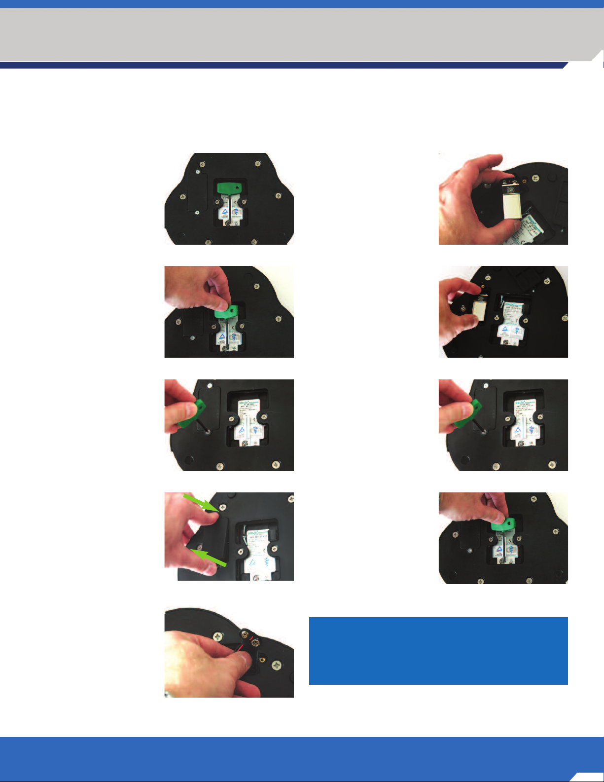
3.1.1 Wireless Foot Pedal Installation Procedure
1. Make sure the laser is
completely turned
off before replacing the
battery in the foot pedal.
2. Place the pedal face
down on a hard, clean
surface, Fig. 3.1.1a.
3. Remove the hexdriver
from its holder on the
underside of the pedal.
Lift up on the long end,
and working the long
end up and down, pull
the hexdriver from its
holder, Fig. 3.1.1b.
4. Insert the hexdriver into
the screw holding down
the battery cover. Rotate
the hexdriver counterclockwise until the screw
comes out completely,
Fig. 3.1.1c.
5. Repeat for the other
screw holding down the
battery cover.
6. Push down on one
end of the battery cover
while simultaneously
lifting up on the other
end to remove the
battery cover, Fig. 3.1.1d.
Fig. 3.1.1a
Fig. 3.1.1b
Fig. 3.1.1c
Fig. 3.1.1d
8. Remove the battery from
its packaging and attach
the battery to the
terminal, Fig. 3.1.1f.
9. Place the battery in the
well, with the connector
to the same side as
where the wire leads
emerge from the
housing, Fig. 3.1.1g.
10. Replace the battery
cover, and replace the
two screws. Turn the
hexdriver clockwise to
tighten the screws. The
screws are sufficiently
secure once they
no longer turn with
gentle finger-applied
force. Do not overtighten, Fig. 3.1.1h.
11. Replace the hexdriver
back in its holder,
Fig. 3.1.1i.
12. Place the pedal face up.
Allow at least 1 minute
after completing this
procedure before
turning on the laser.
Fig. 3.1.1f
Fig. 3.1.1g
Fig. 3.1.1h
Fig. 3.1.1i
7. Locate the battery
terminal inside the
well and pull the
terminal out. Do not
pull excessively on the
wires, Fig. 3.1.1e.
Fig. 3.1.1e
NOTE: An extra 9 volt Lithium battery
should be kept in your office inventory as
the battery should be replaced every 100
hours of continued operation.
O D Y S S E Y
®
TM
Navigator
3 W A T T D I O D E L A S E R
9
Page 10
Section 3
LASER ASSEMBLY INSTRUCTIONS
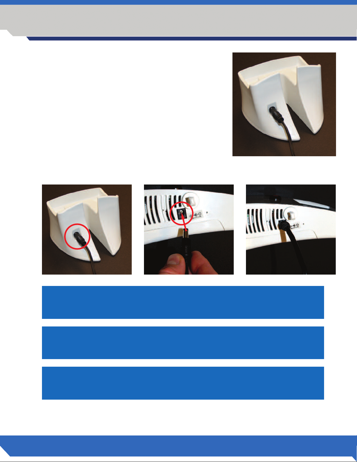
3.1.2 Power Cord Installation
Remove the power cord from the Odyssey Navigator package and plug
the power cord into the appropriate receptacle on the back of the laser
cradle. See Fig 3.1.2 Plug the power cord into a 110 Volt AC outlet
rated at 60Hz. Use only the power supply that comes with the device.
Use of other power supplies may damage the device or cause electrical
shock.
3.1.3 Direct Power Supply
If immediate power is needed and the battery is not charged, unplug the power cord from the cradle, Fig. 3.1.3a,
and plug it directly into the laser, Fig. 3.1.3b and 3.1.1c.
Fig 3.1.3a Fig 3.1.3b Fig 3.1.3c
NOTE: DO NOT leave the AC cord attached to the laser or cradle when the power
supply is unplugged from the wall as this might inadvertently drain the battery.
Fig 3.1.2
10
NOTE: The battery will be charged if the cable is plugged directly into the laser.
The laser can be switched on or off for the battery to be charged.
NOTE: To prevent power surges due to electrical storms or spikes in line voltage,
you should use a power strip with a circuit breaker or unplug the laser when you
are not present.
T h e L e a d e r i n D i o d e L a s e r s .
Page 11

LASER ASSEMBLY INSTRUCTIONS
3.1.4 Connection of Handpiece Assembly to the Laser
1. The handpiece assembly is already installed when you receive your new
Odyssey Navigator Diode Laser. Please leave the handpiece assembly
connected to the laser unit unless you have to switch handpiece
assemblies or if you have to ship the laser for technical reasons.
Disconnecting the handpiece for even short periods can lead to
contamination of the precision polished end of the fiber connector.
This may result in reduced power output of your laser over time.
Fig 3.1.4.a
2. If you have to disconnect the cable, keep the fiber tip connector
of the handpiece and the connector on the bottom of your Odyssey
Navigator clean. Use a protective plastic sleeve from a disposable tip to
protect the end of the handpiece assembly at any time and be sure
not to touch the precision polished end of the connector. Fig 3.1.4b
Section 3
Fig 3.1.4a
Install the protective metal cap to protect the connector on the bottom of
your laser from dust and other contaminants. The protective metal cap
serves also as protection from accidental firing of the laser. Fig 3.1.4c
Contaminants on the fiber ends may lead to the malfunction
of your handpiece. Please take special care in exchanging
handpiece assemblies.
3. Installation of a handpiece assembly to the laser should be done in a
clean environment. Attach the handpiece fiber assembly by screwing the
knurled connector of the cable into the bottom of the laser unit. Avoid
scratching the end of the fiber connector when inserting the cable.
Fig 3.1.4d
The custom engineered connector at the bottom of your Odyssey
Navigator does not allow operating the laser if there is no handpiece
assembly present. This is a feature for your protection, a Safety Alert
window will pop up on your
screen if you switch on the
laser with out handpiece
installed. Make sure to
moderately hand tighten the
connection of your handpiece
assembly after installation.
Fig 3.1.4e
Fig 3.1.4b
Fig 3.1.4c
Fig 3.1.4e
Fig 3.1.4d
O D Y S S E Y
Navigator
3 W A T T D I O D E L A S E R
®
TM
11
Page 12
Section 3
LASER ASSEMBLY INSTRUCTIONS
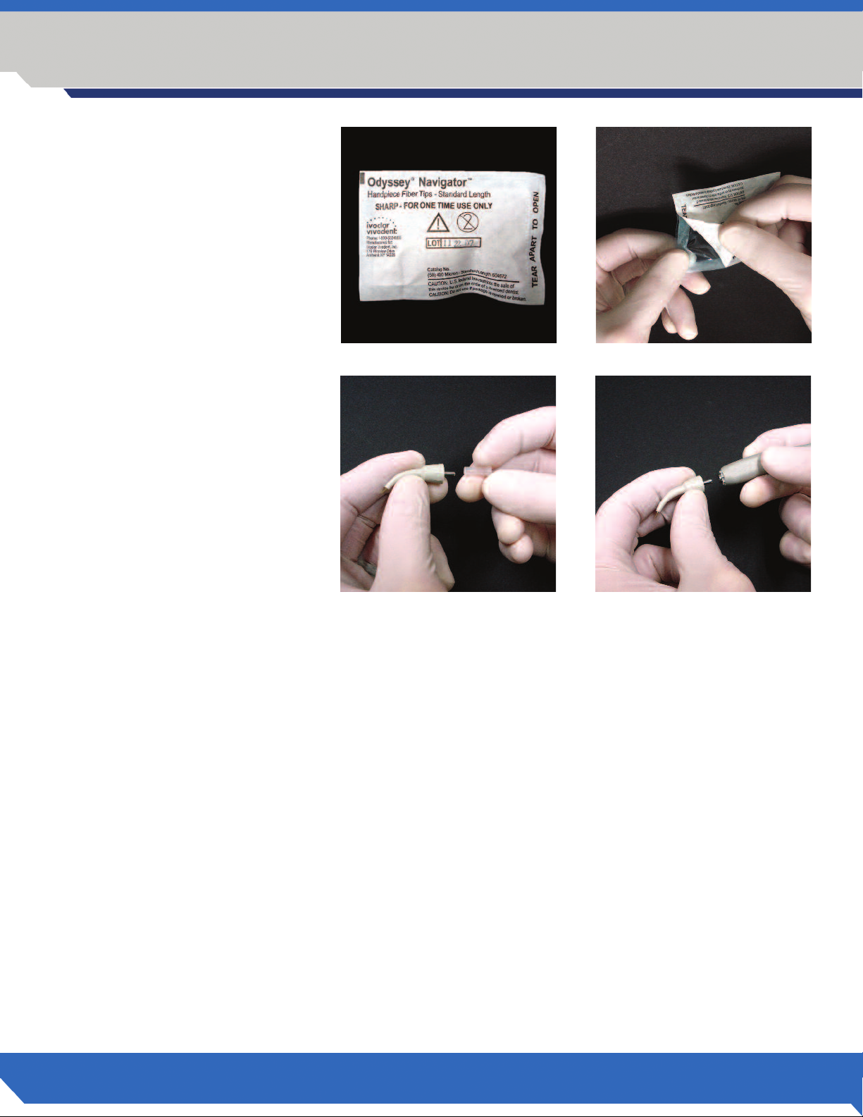
3.1.5 Inserting the unit dose fiber
tip into the handpiece
emove a unit dose fiber tip from
R
its package, remove the plastic
protective cap, and snap it into the
handpiece. Figs 3.1.5a, 3.1.5b and
3.1.5c. Avoid placing your finger
on either end of the handpiece
tips as the tips are gamma irradiated
and have to be clean for optimal
performance and safety. Use gloves
while handling the tips as natural
oils on the fiber or fiber connection
can burn and diminish the effective
transmission of radiant energy
once the laser is installed.
Fig 3.1.5a
Fig 3.1.5b
Fig 3.1.5c
Fig 3.1.5d
12
T h e L e a d e r i n D i o d e L a s e r s .
Page 13

3.1.6 Placing the laser unit in the docking cradle
Place the laser unit in the cradle by tipping the laser unit slightly
forward and inserting it into the cradle. Fig 3.1.6. Do not force
the unit into the cradle and be sure to place the fiber cord
through the cradle opening.
The Odyssey Navigator diode laser is supplied with a
rechargeable lithium polymer battery which provides up to
45 minutes continuous lasing or 8 hours stand-by time,
i.e. laser on, not being charged by cradle or AC power cord.
THE LASER BATTERY MUST BE FULLY CHARGED
BEFORE INITIAL USE.
THE LASER CAN BE SWITCHED ON OR OFF FOR THE
BATTERY TO BE CHARGED.
Allow the battery to charge overnight before first use.
Section 3
LASER ASSEMBLY INSTRUCTIONS
Fig 3.1.6
Recharging a completely discharged battery takes
approximately 5 hours.
3.1.7 Odyssey Navigator Remote Interlock
The Odyssey Navigator Laser is equipped with a Remote Interlock
Jack. The Remote Interlock Jack is provided so that a clinician
may install the laser in a dedicated laser treatment room such
that the laser will be interlocked with the entrance door of the
room. In such an interlocked installation, the laser would shut
off anytime the door is opened, hypothetically, to protect the
person’s eyes who is entering the room. It is recognized that such
installment is not facilitated nor required in many operatories
or clinics. To that end, the Remote Interlock is available to any
practitioner that requires or requests it. The Remote Interlock
Jack is located and clearly labeled on the side panel of the laser.
The miniphono jack is wired in the normally closed position;
meaning that no further action is required to operate the laser without the interlock loop. If the interlock loop is
desired you may purchase the loop from a local electronics store. You need only inform the local electronics store
that you require a mini (1/8”) miniphono jack wired into a normally closed momentary switch and select the switch
design that best suits your needs. To install the loop, install the switch on the door and simply plug the miniphono
jack into the Remote Interlock Jack on the side panel of the laser.
Fig 3.1.7
O D Y S S E Y
Navigator
3 W A T T D I O D E L A S E R
®
TM
13
Page 14

Section 3
LASER ASSEMBLY INSTRUCTIONS
3.1.8 Emergency Shutdown Switch
Before you activate the laser, make
sure the red Laser Stop button is in
the depressed position. The laser will
activate only with the button in the
depressed position. If the laser needs
to be stopped quickly, pushing and
releasing the red Laser Stop button will
immediately shut the laser off.
The Safety Alert Window will appear
on the screen if the button is released.
3.1.9 Powering up the Laser
Turn the laser on using the main power switch on the side of the laser. Fig. 3.1.9
Fig 3.1.8a Fig 3.1.8b
Button depressed—
laser will activate
Button not depressed—
laser will not activate
Fig 3.1.9
3.1.10 Enter the digital key
The Navigator has a keyless entry
system for security purposes. After
turning the power to the “On” position,
the Navigator Screen will appear.
Touch the “Enter” key. Fig. 3.1.10a
The Login screen will appear, touch
the screen and input the digital key
code 1234 and touch the “Enter” key.
Fig 3.1.10b
14
T h e L e a d e r i n D i o d e L a s e r s .
Fig 3.1.10a Fig 3.1.10b
Page 15
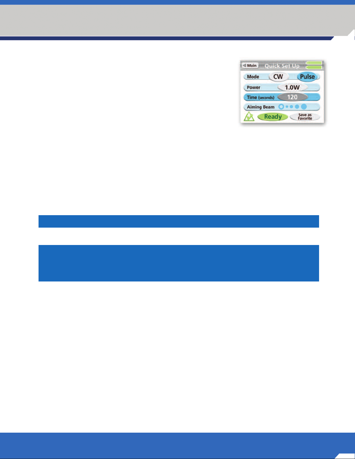
3.1.11 Installation Test
1. After login, from the Main Menu, touch the “Quick Set Up” Button
2. The Odyssey Navigator is pre-set to “Continuous Wave” (CW)
3. Power setting is pre-set to 1.0W
4. Hold the fiber approximately 2-4 mm away from a piece of
articulating paper.
5. Touch “Ready” button – laser is in “Ready” mode.
A green checkmark will be displayed, Fig. 3.1.11,
you will be able to see the aiming beam on the articulating paper
at the end of the fiber tip.
6. Depress the foot pedal to activate the laser.
7. The articulating paper will begin to develop smoke in 1-2 seconds.
3.1.12 Check of the Emergency Shutdown System
1. To check the “Laser Stop” system, simply press and release the red “Laser Stop” button while the laser
is activated. The shut down system will take the laser out of active mode.
Section 3
LASER ASSEMBLY INSTRUCTIONS
Fig 3.1.11
2. To activate the laser, depress the “Laser Stop” button and the laser will resume laser emission.
NOTE: The red Laser Stop button should be depressed for the laser to activate.
Remember: Always test fire the laser outside the mouth before using it on a
patient. The doctor or hygienist, the patient and any staff member present in the
operatory should be wearing the appropriate safety eyewear whenever the laser is
being operated. Strict adherence to protocols for safe laser use is essential.
O D Y S S E Y
Navigator
3 W A T T D I O D E L A S E R
®
TM
15
Page 16
Section 3
LASER ASSEMBLY INSTRUCTIONS
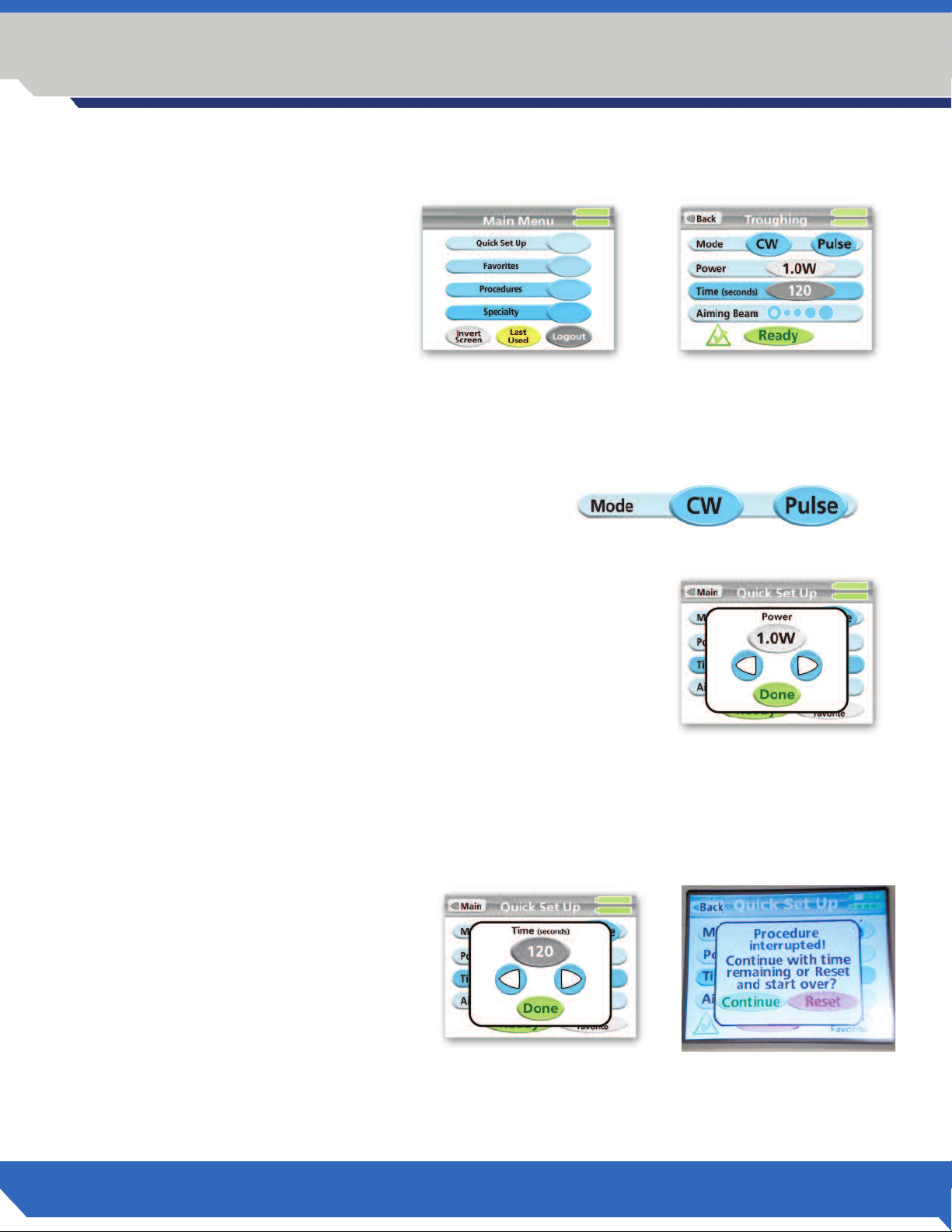
3.1.13 Touch Screen Menu
The Main Menu screen gives you the
choice to use a ”Quick Set Up” (Fig
3.1.13a) - with settings you designate
for each procedure–or you may select
a pre-set program sorted in alphabetical order under the “Procedures”, or
under the “Specialty” categories, Fig.
3.1.13b. The settings are portrayed
with four adjustable settings: Mode,
Power, Time and Aiming Beam. The
settings can be changed as desired for
any of the program modes and saved
as“Favorites” if needed.
Mode
Mode refers to “continous wave” or “pulsed power,
Fig. 3.1.13c. Use the MODE key to toggle back and forth
between Continuous and Pulse as desired. The chosen mode
is displayed in gray color.
Fig 3.1.13a
Fig 3.1.13b
Fig 3.1.13c
Power
Depressing the Power setting allows the operator to adjust the power settings from 0 to 3 watts in 0.1W increments, Fig. 3.1.13d. This control is for
the working beam only. Hold the desired key to rapidly change the value.
Touching the right arrow increases the power, touching the left reduces the
power. Depress “Done” to return to the Main Menu.
Fig 3.1.13d
Time
You have the ability to use the “Time” settings pre-set by procedure or modify the timer by using the arrow keys,
Fig. 3.1.13e. The laser will automatically shut off when the timer returns to 0. Touching the right arrow increases the
time, touching the left reduces the time. Depressing “Done” returns to the main menu.
Releasing the foot pedal in the middle of a
timed procedure will bring up a
“Procedure Interrupted!” window. The
timer will continue with the remaining
time if you press “Continue” or go back
to zero and start over if you press “Reset”,
Fig. 3.1.13f.
Fig 3.1.13e Fig 3.1.13f
16
T h e L e a d e r i n D i o d e L a s e r s .
Page 17

Section 3
LASER ASSEMBLY INSTRUCTIONS
iming Beam
A
The Odyssey Navigator diode laser is actually two lasers in one, the infrared 810 nm wavelength laser which
performs the actual treatment of the soft tissue, the “working beam” and the 650 nm “laser pointer” which
illuminates the focal point of the “working beam” allowing the operator to aim prior to and during laser
ctivation. In addition, the aiming beam control allows for five levels of illumination ranging from off to
a
maximum intensity. The open circle indicates no aiming beam and the solid blue circle indicates the brightest
aiming beam.
Fig 3.1.13g
To adjust aiming beam intensity, the bar is depressed which activates the above screen, Fig 3.1.13g. The arrows
are depressed upward or downward as desried. Each increment adjusts the aiming beam intensity by 20%. When
complete, depress the “Done” key to return to the setting screen. Check if the new settings meet your desired
aiming beam intensity, Fig 3.1.13h.
No aiming beam Maximum aiming beam power
Fig 3.1.13h
Ready Indicator
This illuminates when the READY key is pressed. It will blink for 3 seconds, then remain
steady. Once steady, the aiming beam will be activated and the laser is ready to be fired.
Laser On
This illuminates when the foot pedal is depressed, indicatingthat the working beam
(810nm) energy is being emitted.
Favorites
Any combination of settings can be easily saved for convenience
with a user defined name. Press the button “Save as Favorite” in
the lower right corner of the touch screen when you are in Quick
Set Up Mode or in on one of the Specialty Procedure Screens.
Confirm “yes” on the next pop-up window (Fig 3.1.13i) and
enter a descriptive name by pressing the respective
buttons until you have the next letter in the box in the upper
right corner of your screen. Either confirm this letter by touching
it in the upper right corner or press another button or wait more than 2 seconds before
pressing the same button. As a result this letter will be transferred to the name field in the
middle of the dark grey portion of the upper screen (Fig 3.1.13j). It is possible to delete
one character at a time by pressing “Clear”. Note: Only lower case letters possible.
Fig 3.1.13i
Fig 3.1.13j
Press “Save” after the name is complete and confirm with “OK” (Fig 3.1.13k) to save your
entry in a special non-transient memory for future use.
Favorites can be easily deleted by choosing a particular favorite setting from the
“Favorites” menu and by pressing “Delete Favorite” and confirming with “Yes” in a second step.
O D Y S S E Y
Navigator
3 W A T T D I O D E L A S E R
Fig 3.1.13k
®
TM
17
Page 18
Section 3
LASER ASSEMBLY INSTRUCTIONS
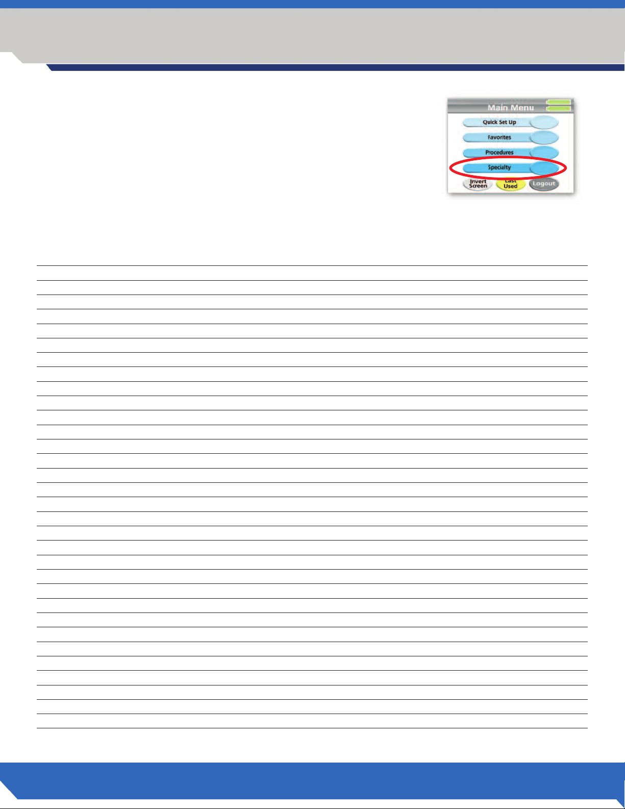
3.1.14 Preset Programs
The Odyssey Navigator comes with procedure specific settings installed.
The Procedures are accessed from the Main Menu by depressing
“Procedures.” Procedures may also be accessed through the “Specialty”
category. By accessing in this way, the procedures are sorted according to
speciality, Fig. 3.1.14.
After selecting a procedure, the settings may be manually adjusted to suit
your needs during a clinical procedure. The settings represent a good starting
point and can be adjusted at any time.
Program Screen Name Tip Preparation Technique Mode Power Timer
Abscess initiated contact Continuous 1.0 W set to 0
Apthous Ulcer un-initiated non-contact Pulse 1.4 W 30 seconds
Biopsy initiated contact Continuous 1.0 W set to 0
Contouring initiated contact Continuous 0.8 W set to 0
Denture Sore un-initiated non-contact Pulse 2.0 W 30 seconds
Distal Wedge initiated contact Continuous 1.5 W set to 0
Draining of Abcesses initiated contact Continuous 0.9 W set to 0
Emergence Profile initiated contact Continuous 0.8 W set to 0
Expose Teeth initiated contact Continuous 1.0 W set to 0
Fibroma initiated contact Continuous 1.0 W set to 0
Flap initiated contact Continuous 1.0 W set to 0
Frenectomy initiated contact Continuous 0.8 W set to 0
Gingivectomy initiated contact Continuous 1.0 W set to 0
Gingivitis initiated contact Continuous 0.4 W 20 seconds
Gingivitis Therapy un-initiated contact Continuous 0.8 W 20 seconds
Gingivoplasty initiated contact Continuous 1.0 W set to 0
Hemostasis un-initiated non-contact Continuous 1.0 W set to 0
Herpetic Lesion un-initiated non-contact Pulse 1.6 W 30 seconds
Hypertrophic tissue initiated contact Continuous 1.5 W set to 0
Implant exposure initiated contact Continuous 1.0 W set to 0
Lesion Removal initiated contact Continuous 1.0 W set to 0
Mucocele initiated contact Continuous 0.9 W set to 0
Operculectomy initiated contact Continuous 1.5 W set to 0
Ovate Pontic initiated contact Continuous 1.0 W set to 0
Periimplantitis un-initiated contact Continuous 1.0 W set to 0
Perio - Chronic un-initiated contact Continuous 0.5 W 30 seconds
Perio - Severe un-initiated contact Continuous 0.7 W 45 seconds
Socket Treatment un-initiated non-contact Continuous 0.8 W set to 0
Sulcular Debridement un-initiated contact Continuous 0.8 W 30 seconds
Tissue Tag initiated contact Continuous 1.5 W set to 0
Tissue Welding initiated contact Continuous 0.6 W set to 0
Tongue Tie initiated contact Continuous 1.0 W set to 0
Troughing initiated contact Continuous 0.8 W set to 0
Vestibuloplasty initiated contact Continuous 1.0 W set to 0
Fig 3.1.14
18
T h e L e a d e r i n D i o d e L a s e r s .
Page 19

Section 3
LASER ASSEMBLY INSTRUCTIONS
3.2 EVALUATING THE FACILITY AND ENVIRONMENTAL CONSIDERATIONS
In order to insure the safe use of the laser in your facility, please check to make sure that the proposed location has the following:
3.2.1 Power Requirements
110 - 240 V AC ±10 % at 50 - 60 Hz
3 Amps
9 volt Lithium battery for the foot pedal
3.2.2 Heating and Ventilation
The laser should be operated in areas with the optimum temperature range of 20º - 30ºC (68º - 86º F).
3.2.3 Transport and Storage
Avoid storing or transporting the laser in temperatures below 0ºC (32º F).
3.2.4 Lighting
Overhead lighting and or dental unit light should provide enough illumination to allow good operator vision when
activating the laser intra-orally.
3.2.5 Combustible Chemicals and Gases
All gases that are combustible or support combustion and are used in the operatory area where the laser is in use must
be turned off during the procedure. Cleaning supplies or other flammable chemical compounds should be stored in an
area away from the surgical site in order to avoid possible combustion (e.g. alcohol gauze, liquid topical anesthetics).
3.2.6 High Speed Vacuum Systems
Plume evacuation is a priority when vaporizing tissues. The Clinician or operator, and their chair-side assistants
should keep themselves and the patient safe by using a high volume vacuum system and filtration masks that are
suitable for virus and bacterial control. Please use a high filtration mask with 0.1 micron or less to protect from
airborn viruses or bacterial particles.
3.2.7 Access and Visual
Access to the treatment area should be restricted while
the laser is in use. A Laser In Use Safety Sign should be
adjacent to the entrance to the treatment area, Fig. 3.2.7.
Fig 3.2.7
O D Y S S E Y
Navigator
3 W A T T D I O D E L A S E R
®
TM
19
Page 20

Section 3
LASER ASSEMBLY INSTRUCTIONS
3.2.8 Odyssey Navigator Diode Laser Frequency
The Odyssey Navigator diode laser wireless technology is electronically coded. Each pedal and Odyssey Navigator
diode laser share a UNIQUE SERIAL NUMBER INTERLOCK protocol for reliable operation:
• An Odyssey Navigator pedal communicates with only one Odyssey Navigator diode laser; there is 2-way
electronic code which must be verified for every transmission and acknowledgement. The pedal and laser
unit are interlocked to only each-other’s electronic codes.
• If data from another Odyssey Navigator pedal is ever received, embedded verification measures ensure that
it will be ignored.
• If data were ever received from another wireless device with a compatible modulation scheme
(2.4GHz frequency), it would immediately be ignored in the same way. In summary, the wireless receivers
in the Odyssey Navigator diode laser have less than 2% of the output power of typical Bluetooth or Wi-Fi
devices, and therefore have no significant potential as an interference source. Odyssey Navigator wireless
receiver modulation is incompatible with Wi-Fi or Bluetooth devices, and therefore cannot mistakenly receive
data from such devices. Through a unique internal communication structure, and strict verification of all
incoming data, nothing activates an Odyssey Navigator diode laser except the wireless pedal which it is
paired with via electronic code.
20
T h e L e a d e r i n D i o d e L a s e r s .
Page 21

Section 4
SAFETY CONSIDERATIONS
he safe use of the Odyssey Navigator is the responsibility of the entire dental team, the laser safety officer appointed, and
T
the dental office team. Protocols for the safe use of lasers have been developed by a combination of medical and dental professionals working in concert with educators at the university level, scientists and laser manufacturers. Dental professionals
have had to develop protocols and guidelines for using the laser on oral soft tissues. Sound judgment and the concern for
atient safety should be the basis of all laser care.
p
Usually, states or provinces do not have a specific licensure requirement for use of a laser by a dentist. Certain states and
provinces, like Texas and Alberta, however, require the dental office to be certified and inspected prior to using a laser. The
user is advised to check with the local Dental Association or State website to be aware of any specific requirements in your
location. Some states require a hygienist to attend licensure training that includes both a lecture and hands-on training. Prior
to using the laser, the hygiene applicants are required to pass a proficiency test for certification. These courses are usually
taught by members of the Academy of Laser Dentistry who possess instructor credentials.
Worker safety is the responsibility of the employer. ANSI standard Z136.1 (US) and CSA standard Z386-01 concerning Laser
Safety in Health Care Facilities are sources for analyzing safety with respect to medical lasers. Ivoclar Vivadent Inc. recommends implementation of a Laser Safety Program for the safety of your patients and office staff in connection with the use of
the Odyssey Navigator Diode Laser.
4.1 LASER SAFETY PROGRAM
We recommend implementation of a Laser Safety Program appropriate for your dental office. The plan may include
the following:
• Delegation of authority and responsibility for supervision and control of the laser to a designated Laser
Safety Officer;
• Minimum Training requirements for users of the laser;
• Security to restrict unauthorized use of the laser;
• Standard operating procedures to regulate the work environment in order to protect the patient and
office staff from laser hazards.
The safe use of a laser is the responsibility of the Laser Safety Officer (LSO) who can be a full or part-time employee,
or the laser operator. It is their responsibility to train the staff, maintain records concerning training and the laser’s
performance, perform safety checks and prepare the laser for use on a daily basis. The LSO must keep records of
any incidents that relate to the failure of the laser or any adverse effects related to laser therapy and report such
incidents as prescribed by law. The LSO assures that a medical follow-up has been sought or has occurred following
any adverse incident during treatment. The LSO is responsible for training of all office personnel who are involved
with the laser preparation and use. Daily checks of the facility and equipment are also the LSO’s responsibility. The
LSO should test fire the laser each day prior to beginning each treatment procedure. For more information on the
contents of a Laser Safety Plan, you can review ANSI Standard Z136.3 for Safe Use of Lasers in Health Care Facilities
(US) or CAN/CSA-Z386-01 Laser Safety in Health Care Facilities(Canada).
4.2 CONTINUING EDUCATION
The Laser Safety Officer should insure that the operator and staff attend laser courses taught by qualified laser
educators. Ongoing reviews of laser safety procedures should be a part of normal office routine.
O D Y S S E Y
Navigator
3 W A T T D I O D E L A S E R
®
TM
21
Page 22

Section 4
SAFETY CONSIDERATIONS
4.3 IN-OFFICE SAFETY ISSUES
4.3.1 Lighting
Always use the Odyssey Navigator in a well lighted and ventilated area.
4.3.2 Combustible chemicals or gases
Make certain that chemicals or gases capable of supporting or causing combustion are not present when using
the laser (e.g. alcohol gauze, liquid topical anesthetics).
4.3.3 Safety Eyewear
While using the Odyssey Navigator laser, doctors, hygienists, auxiliary staff, patients, and anyone attending them
in the operatory must wear the appropriate safety eyewear that has been designed for use with the 810 nm
wavelength. Never point the laser tip directly at the face, eyes or skin of anyone while emitting energy. The aiming
beam is also capable of causing eye damage.
4.3.4 Test Firing the Laser
Always test-fire the Odyssey Navigator prior to using it intra-orally using a power of 1 Watt continuous wave or less.
Place the laser in the ready mode, then, activate the laser for 1-2 seconds while aiming the fiber onto a 2X2 gauze
sponge wetted with water. Do not use alcohol or any other combustible material to wet the 2X2 sponge as it may
ignite. Please be aware the the 810 nm working beam is invisible to the human eye! You can only see the red
650 nm aiming beam if it is turned on.
4.3.5 Power Changes With Fiber Changes
Switching to a smaller diameter fiber will increase the density of the power at the fiber tip. As a result, you may need
to adjust your power downward. Increasing the power may be required when switching to a larger diameter fiber. In
order to achieve the same rate of work after changing fiber diameters, remember this: a smaller diameter fiber will
require less power and conversely, a larger diameter will require more power.
4.3.6 Danger - Laser In Use Signage
Each operatory where the Odyssey Navigator is used should have a “laser in use” sign placed at the operatory
entrance when a procedure is in progress. This signage will help to eliminate eye damage caused by inadvertent
exposure to laser energy. Additional signs can be ordered through Ivoclar Vivadent Customer Service.
4.3.7 Sharps Disposal and Sponge Removal
Remove cleaved fiber remnants and place them into a Sharps container for disposal. Used fiber tips should also be
disposed of in a Sharps container. All sponges used for cleanup of lasers and fibers should be disposed of in a bag
for contaminated soft products.
4.3.8 Plume Evacuation
Use high volume evacuation suction during procedures to remove laser smoke or ‘plume’ debris. Use masks suitable
for viral filtration. Caution - laser plume may contain viable tissue particulates. Please use a high filtration mask with
0.1 micron or less to protect from airborn viruses or bacterial particles.
4.3.9 Laser Security
22
To prevent the unintentional use of the laser while not in use, the unit should be switched off. An electronic
password is required to be entered before the unit may be used again. This code should be maintained by the
Laser Safety Officer.
T h e L e a d e r i n D i o d e L a s e r s .
Page 23

4.3.10 Emergency Shutdown Options
Any of these mechanisms can be used to shut down the emission of laser energy in a real or perceived emergency:
1. Depress and release the emergency shutdown button
2. Foot Pedal – remove your foot to stop lasing
3. Switch the Power/Fan to the off position (O)
4. Power Cord – unplug from the wall outlet
4.3.11 Hard Tissue Procedures
The Odyssey Navigator diode is not an appropriate laser for hard tissue procedures. The diode laser is attracted to
melanin, hemoglobin and, to some extent, water and oxygenated hemoglobin. Avoid prolonged exposure of the
energy when working in and around the cervical areas of the tooth. Due to the thin layer of enamel in this area, the
laser’s energy may be absorbed by the hemoglobin in the pulp and pulpal hyperemia may occur. Extended exposure
to laser energy could lead to pain and possible pulpal necrosis.
Section 4
SAFETY CONSIDERATIONS
O D Y S S E Y
Navigator
3 W A T T D I O D E L A S E R
®
TM
23
Page 24

Section 5
OPERATING THE LASER
5.0 INTENDED USES
The Odyssey Navigator is intended to be used for oral soft tissue surgery including: sulcular debridement
of diseased or fibrous tissue, i.e. excision and biopsy, gingivectomy and gingivoplasty, lesion (tumor) removal,
fibroma removal, tissue retraction (troughing), aphthous ulcers, gingival hyperplasia (excision and recontour), crown
lengthening, operculectomy, frenectomy and photocoagulation. In addition, the Odyssesy Navigator laser may be
used for laser periodontal procedures, including: laser soft tissue curettage, laser removal of diseased, infected,
inflamed and necrosed soft tissue within the periodontal pocket, removal of inflamed edematous tissue
affected by bacteria penetration of the pocket lining and junctional epithelium. The Clinical Guide supplied with
your Odyssey Navigator laser provides suggestions for laser settings for certain
procedures, as does the pre-set programs in the Odyssey Navigator laser.
5.1 STANDBY AND READY STATUS
Stand By mode is indicated by the laser having power and the digital key
code entered to access programming options. However, laser energy will not
be emitted even if the foot pedal is depressed. Ready mode is achieved by
touching the Ready button found on the program screens. A green check
mark on the screen will evidence Ready Mode, Fig. 5.1. Once Ready is
touched, the laser may be activated by depressing the foot pedal.
5.2 CONTINUOUS OR PULSE MODE
Ready Mode Indicator
Fig 5.1
The Odyssey Navigator will deliver energy in either a
continuous wave (CW) mode or in a pulsed mode which
are called temporal emission modes (time related modes).
Selecting the appropriate mode is a factor of controlling
target tissue temperatures and the efficiency of energy delivered. The pulse duration (0.05 seconds) and the number
of pulses per second (10) have been fixed by the manufacturer using a 50% duty cycle. This setting can not be adjusted.
The chosen mode is displayed in gray color.
5.2.1 Continuous Wave (CW) Mode
Setting the laser to the CW mode, allows you to deliver the specified amount of power in one second. Setting the
laser to 2 Watts CW will allow you to deliver 2 Watts per second as long as you have the foot pedal depressed. The
CW mode is generally the fastest way to ablate tissues but heat can build up and cause collateral damage to the target and adjacent tissues. Cool the tissues being lased by using periodic blast of air from a triplex syringe and high
speed suction. You may use water to cool in areas where there is prolonged exposure to the laser’s beam. Avoid
using the air syringe when you have an opening in soft tissue adjacent to or within the surgery site. An
air embolism may occur as a result of air captured within the tissue during the cooling process.
5.2.2 Pulsed Energy Mode
Pulsing the laser energy will allow some cooling of the tissue in between emissions of energy. The “duty cycle” is
the percentage of the time in each second that the laser is emitting energy. The pulses per second, the duty cycle
and the energy intensity per pulse will determine your average power. In the pulsed mode, the Odyssey Navigator
is programmed to deliver 10 pulses per second with each pulse lasting for 0.05 seconds. The duty cycle is set for
50% so you will have 1 energy pulse with 1 period of rest with no energy between each pulse. The result will be an
average power per second that will be 50% of what you have set the laser for. Therefore, when using pulsed energy,
you will have to adjust your power upward in order to achieve the same rate of work as the same power set in CW,
i.e. 2 Watts of Pulsed energy will be the same average power output as 1 Watt CW.
24
T h e L e a d e r i n D i o d e L a s e r s .
Page 25

5.3 TISSUE RESPONSES TO LASER ENERGY
Maximum results will be achieved by regulating the power and the speed that the operator moves the fiber tip.
Tissue Charring is an undesirable after effect of too much power or the tip moving too slowly. Always use the
least amount of power necessary to complete your procedure. The ideal tissue response will show little or no
discoloration after lasing and there will be less residual damage and faster healing. Avoid penetrating or damaging
the periosteum, and do not use the laser on alveolar bone. Because the laser energy is attracted to melanin and
hemoglobin, power must be reduced when treating patients with darker soft tissue. Always begin lasing with the
lowest power you can use to remove or modify the target tissues. Avoid damage to the gingival sulcus by moving
the fiber tip quickly and using low power settings. Check so that no shard is present on the tip. A shard may act as a
miniature scalpel and damage the small blood vessels, thus preventing hemostasis and coagulation.
5.4 SYSTEMS PROCEDURES
5.4.1 Treatment Area Requirements
The laser should be placed in an area with good ventilation and lighting. The electrical service required is a
110 - 240 Volt AC outlet 50 - 60 Hz. The area where the laser is placed should be free of standing water.
Combustible gases or those that support combustion should be turned off and all flammable materials or chemicals
stored in the area should be removed.
Section 5
OPERATING THE LASER
5.4.2 Foot Pedal
It is recommended to use a 9 volt Lithium battery to power the cordless foot pedal. This type of battery has been
tested to last for over 100 hours of foot pedal operation. When the battery voltage begins to drop, the foot pedal
will begin to beep, signaling that you have approximately 2 hours of operating time left before the battery life is
completed.
NOTE: A 9 volt Alkaline battery may be used, however the life expectancy of an Alkaline battery is less than 35 hours
of operating time.
5.4.3 Unit-Dose Fiber Tip
Make sure the tip is “snapped” onto the handpiece. Please read chapter 6.3.4 for test instructions.
5.4.4 Fiber Preparation/Initiation
To prepare the fiber for cutting, if your procedure calls for it, set the power to 1 watt, activate the laser, and touch
the tip to black or blue articulating paper. This initiates the tip for cutting.
5.4.5 Emergency Shut Off Button
Check the Emergency Shutdown Button to see that it is depressed, if not, gently depress the button.
5.4.6 Digital Key
Activate the digital key by entering 1234 on the touch pad. The Main Menu screen will appear.
5.4.7 Setting Parameters for the Quick Set Mode
Review your power and mode requirements and then depress the mode button to select either Continuous (CW)
or pulsed mode.
O D Y S S E Y
Navigator
3 W A T T D I O D E L A S E R
®
TM
25
Page 26
Section 5
OPERATING THE LASER
5.4.8 Select Your Power
Press the arrows until you have reached the desired Wattage. Beginning with a low of 0.1 Watts, the power increases in increments of 100 mW up to a maximum of 3.0 Watts (CW). By holding the arrow keys to increase or decrease
the power, you can have an un-interrupted increase until you reach your desired power.
5.4.9 Selecting Programs
At the Main Menu Screen you will have choices to select a program by scrolling the “Procedures” list in alphabetical
order, or by choosing “Specialty” which lists programs grouped by specialty categories such as Cosmetic or
Periodontics. You can also create your own Favorites programs by following the screen instructions under “Save as
Favorite”.
5.4.10 Aiming Beam
The aiming beam laser pointer can be turned on and off by pressing the aiming beam button on the laser control
panel. Press the arrow buttons to progressively increase or decrease the aiming beam intensity from 0 (off) to full
intensity. Each circle represents approximately 20% of the aiming beam output.
NOTE: Adjusting the intensity of the aiming beam has no effect on the output power of the primary working laser.
5.4.11 Tips
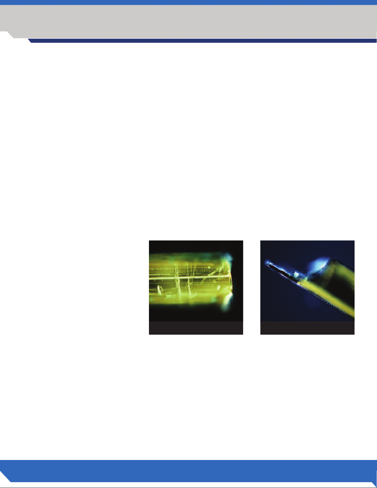
The tips are provided pre-cleaved and polished for immediate use. Examine the Fiber Tip to insure that there is not a
fiber tip shard (see Fig 5.6.11a and b for comparison). The shard can act like a miniature scalpel and cause damage
while diffusing the light beam and lowering the laser’s power.
Good cleave – Fig. 5.4.11a
Poor cleave – Fig. 5.4.11b
5.4.12 Procedure
1. Depress the Ready button and the aiming beam should light after 2 seconds. Review your power and mode
requirements and then depress the mode button to select either CW or Pulsed mode.
2. Test fire the laser outside the mouth by activating the laser into a 2 X 2 gauze sponge that has been wetted
with water to prevent combustion. Do not use flammable liquids to wet the sponge.
Fig 5.4.11a
Fig 5.4.11b
26
3. Initiate tip as described in Chapter 6.1.3, if needed.
4. Depress the foot pedal and make short quick strokes at the lowest power that you can to remove the target
tissues while lightly contacting it.
5. Remove your foot from the foot pedal and use a clean 2 X 2 gauze sponge wetted with water to remove debris
from the fiber tip. Do not use flammable liquids to wet the sponge.
T h e L e a d e r i n D i o d e L a s e r s .
Page 27

Section 5
OPERATING THE LASER
. Remove your foot from the foot pedal and touch the Ready button to place the Laser in Standby Mode until
5
you are ready to start another procedure.
6. Remove the unit dose fiber tip and dispose in a suitable biowaste Sharps disposal.
7. Remove the handpiece sleeve only and follow the autoclave instructions.
8. If you are not going to be starting another procedure, return back to the Main Menu and press Logout. It is
now safe to turn the power button to the OFF position.
9. Record the Powers and total lasing times used for each procedure in the patient’s chart.
Example:
Patient Name: Mary Jones
Procedure: Gingivectomy # 6 and # 7
#6 Lasing time 90 seconds @ 2.0 Watts CW air cooled, 810 nm wavelength
#7 Lasing time 60 seconds @ 1.5 Watts CW air / water spray, 810 nm wavelength
5.4.13 Odyssey Navigator Self Diagnostic and Monitoring
When the Odyssey Navigator Laser’s microprocessor detects an issue with performance it will immediately notify you
by way of an audible beep. There are two different ways in which the Odyssey Navigator will alert you to any issues:
1. Continuous audible beep when foot pedal is engaged. If you are operating the Odyssey Navigator with the foot
pedal engaged and the Odyssey Navigator emits a constant audible beep and stops the beep when you release
the foot pedal, the microprocessor has determined that the laser power output has fallen below the set level. In
this event the Odyssey Navigator Laser should be turned off and allowed to sit for 5 minutes then turned on
again. If the Odyssey Navigator then performs without beeping, the microprocessor has been able to make
operational adjustments to the laser and the unit will perform its functions. If, however, upon restart the unit
continues to beep when the foot pedal is engaged, the microprocessor was unable to adjust the unit enough
and the unit will need to be sent in for adjustment.
2. Continuous audible beep when the unit is turned on. If you are operating the Odyssey Navigator and it emits a
constant audible beep whether or not the foot pedal is engaged, the microprocessor has determined that the
laser has either low power or a general fault has occurred. In this event the Odyssey Navigator Laser should be
turned off allowed to sit for 5 minutes and turned on again. If the Odyssey Navigator then performs without
beeping the microprocessor has been able to make operational adjustments to the laser and the unit will per
form its functions. If, however, upon restart the unit continues to beep, the microprocessor was unable to adjust
the unit enough and the unit will need to be sent in for adjustment.
O D Y S S E Y
Navigator
3 W A T T D I O D E L A S E R
®
TM
27
Page 28

Section 6
SYSTEM COMPONENTS: PREPARATIONS, CARE AND MAINTENANCE
6.0 UNIT-DOSE FIBER TIPS
The fiber optic element of a laser is responsible for carrying the light from the diode array to the tissue being treated.
The dental laser fibers are usually made of quartz, sapphire, silica or a combination of those elements. Quartz/silica is
the most popular product used in diode lasers. Be advised about the potential hazards when inserting, steeply bending or improperly securing the fiberoptics to the handpiece. Radiation exposure may occur in these instances which
could be harmful to yourself, your staff and your patient. Special care should be taken not to break or snap the fiber
when removing tips from packaging. As the Aiming Beam passes down the same delivery system as the Working
Beam, it provides a good method of checking for integrity of the delivery system. If the aiming beam spot is not
present at the distal end of the delivery system, its intensity is reduced, or it looks diffused, this is a possible indication of a damaged or not properly working delivery system.
6.0.1 General
The unit dose fiber tips contain a pre-cleaved and pre-stripped piece of fiber. They are individually wrapped and
delivered gamma irradiated. They are designed for single application and should be discarded after each use.
If necessary, the tip can be cleaved using the cleaving procedure in 6.1.2.
6.0.2 Replacing a Unit Dose Fiber Tip
Remove plastic cover and push the tip into the handpiece until it locks into place. Do not touch the polished fiber
connector after removing the plastic cover and keep the fiber connection clean.
6.1 FIBER PREPARATION
The unit dose tips are pre-stripped and pre-cleaved for immediate use. If necessary, the tip can be cleaved. See
instructions below.
6.1.1 Quartz/Silica Fiber
The fiber is fairly flexible but can be broken if bent into a small circle or bent at an angle of 90 degrees. The
cladding will burn as protein from the gingival accumulates on the fiber and will deteriorate the tip. It can fracture
if not cleaved once the blackened area has reached 3-4 mm. Stop lasing and wipe off the tip regularly as you work
to avoid accumulation of protein debris. Use water on a 2 x 2 gauze sponge to clean the tip. Do not use flammable
materials like alcohol products when cleaning a hot tip. Dispose of all small fiber remnants after you have cleaved
the fiber. They should be kept in a small box with a lid until they can be properly disposed of in a Sharps container.
28
T h e L e a d e r i n D i o d e L a s e r s .
Page 29
SYSTEM COMPONENTS: PREPARATIONS, CARE AND MAINTENANCE
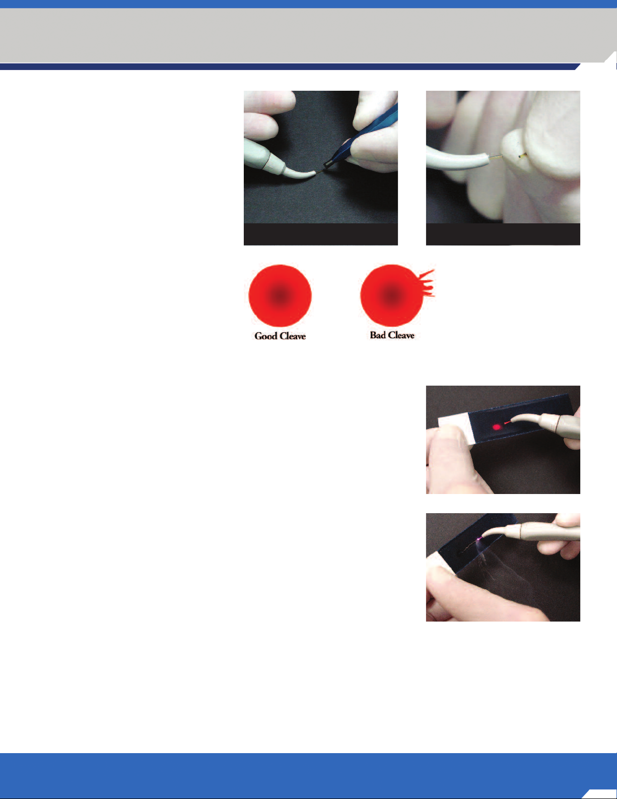
6.1.2 Cleaving the Fiber
The tips are designed for single use
application.However, if the need
arises to cleave the tip the operator
should place their index finger at
the spot of the proposed cleave
(Fig. 6.1.2a) so as to stabilize the
fiber. Using the pen style cleaver,
draw the cleave blade across the
top of the fiber with enough pressure to ”score” the fiber (Fig.
6.1.2b). The fiber should break at
the score mark. The comparison–
good versus bad cleaves–is shown
in Fig 6.1.2c and Fig 6.1.2d, visible
when you poin the aiming beam
onto a white surface.
Section 6
Fig 6.1.2bFig 6.1.2a
6.1.3 Initiating the Fiber
Some procedures require that the fiber tip be initiated. The tip of the fiber
can be prepared to retain heat by introducing it to a dark material. The
easiest way to prepare the tip is to lightly move the end of the fiber across
a piece of articulating paper at about 1 Watt CW Fig. 6.1.3a and Fig. 6.1.3b.
The tip will retain pigment which will make the tip glow. Do not exceed
contact time of 1 second.
6.2 LASER MAINTENANCE
6.2.1 Laser Chassis Disinfection
The exterior of the laser should be cleaned using a liquid disinfectant similar
to BIREX™ or CIDEX®. Do not spray the disinfectant directly on the
Chassis as liquids could damage the LCD display. Apply with a gauze
sponge or wipe. Do not use abrasive materials to clean the system. Place an
adhesive barrier material over the LCD screen prior to treating the next patient.
6.2.2 LCD Display
Over the lifespan of the device, the display may become opaque from repeated scratches, abrasions and/or organic
debris. This could impair the proper display of information. Should your display show evidence of wear or scratches,
the unit should be returned for service. In the event the LCD display becomes cracked or damaged, the liquid crystal
chemical could leak. Use of the device should be immediately discontinued and the unit returned for servicing in
this case.
Fig 6.1.2c
Fig 6.1.2d
Fig 6.1.3a
Fig 6.1.3b
O D Y S S E Y
Navigator
3 W A T T D I O D E L A S E R
®
TM
29
Page 30
Section 6
SYSTEM COMPONENTS: PREPARATIONS, CARE AND MAINTENANCE
6.2.3 Calibration
The Odyssey Navigator Laser uses solid-state circuitry to continuously monitor the power output, and adjusts the
power supplied to the laser module to keep the output consistent with the user defined setting. If output levels are
more than ± 20% of the set value, the unit is designed to shut down power to the laser, and an audible alarm will
sound. If this happens, the unit should be turned off and allowed to sit for 5 minutes and turned on again. If the
laser then performs without beeping, the microprocessor has been able to make operational adjustments and the
unit will perform its functions. If, upon restart, the unit continues to beep, the unit will need to be sent in for adjustment by a Ivoclar Vivadent, Inc., Service Department.
We suggest that your practice establish an internal calibration program for your laser. Recalibration is recommended
a minimum of once per year based on average usage. Recalibration may be performed by the manufacturer by
returning the unit. In the alternative, you may purchase a calibrated hand held power meter approved for use with
810nm devices to check power output. The laser should be set at 1, 2 and 3 Watts with output checked at each
level. The output display should be within 20% of the meter reading. If not, recleave the fiber and re-check. If the
output display is still outside the 20% tolerance, return the unit to the manufacturer for recalibration. There are no
methods available for the user to adjust the calibration of the unit and the unit chassis must not be removed by the
user for any reason.
6.2.4 Battery Use
The Odyssey Navigator diode laser is supplied with a rechargeable lithium polymer battery which optimally provides
up to 45 minutes continuing lasing time or 8 hours stand-by time i.e. laser on, not being charged by cradle or AC
power cord. If you find the battery runs the laser for 30 minutes or less after being charged for several hours, the
battery may need replacing. A replacement battery can be ordered. To remove the battery, press on the center button while sliding the battery downward, then lift away from the unit. Install the new battery by placing it onto the
back of the laser, the sliding upward until the lock clicks in place. The new battery must be charged overnight prior
to using the laser.
6.3 HANDPIECE STERILIZATION
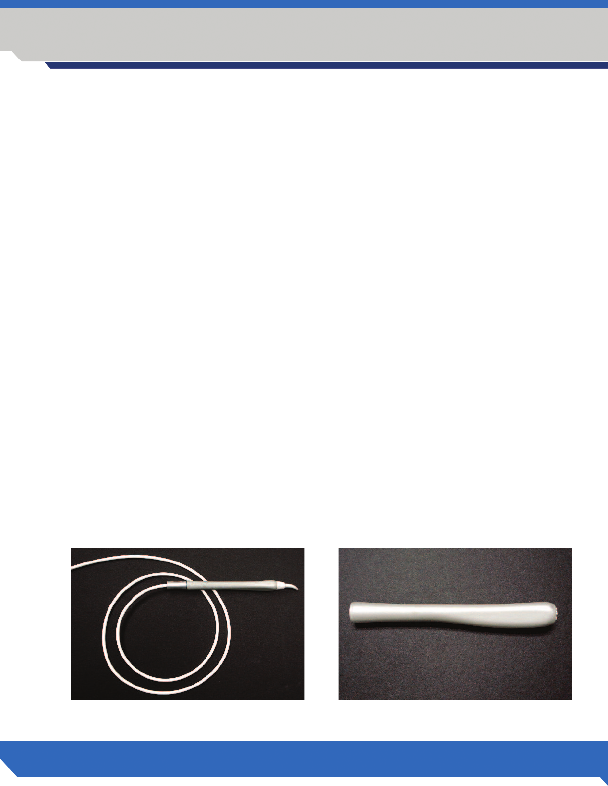
6.3.1 Handpiece Components
For sterilization, the handpiece has two (2) components:
1. handpiece and fiber assembly (Fig 6.3.1a)
2. handpiece sleeve (Fig. 6.3.1b)
30
Fig 6.3.1a Fig 6.3.1b
T h e L e a d e r i n D i o d e L a s e r s .
Page 31

SYSTEM COMPONENTS: PREPARATIONS, CARE AND MAINTENANCE
6.3.2 Recommended Autoclave Procedure
1. Autoclave the handpiece sleeve only.
First remove the unit-dose tip after the procedure. Unscrew the metal
handpiece sleeve counterclockwise and separate from the handpiece.
The recommended autoclave cycle is 132°C at 27 psi for 15 minutes.
Fig 6.3.2a and b.
2. Do not place the laser unit or the fiber cable in the autoclave!
The recommended procedure is to wipe the fiber cablewith a liquid
disinfectant (e.g. Lysol Spray Brand III). Please wear gloves. Do not
disconnect the fiber cable from the laser unit for cleaning procedure.
Fig 6.3.2c.
Section 6
Fig 6.3.2a
Fig 6.3.2b
Fig 6.3.2c
O D Y S S E Y
Navigator
3 W A T T D I O D E L A S E R
®
TM
31
Page 32

Section 6
SYSTEM COMPONENTS: PREPARATIONS, CARE AND MAINTENANCE
6.3.3 Prepare Fiber
The unit dose fiber tips are individually wrapped and gamma irradiated. Fiber tips cannot be autoclaved. They
should be wiped down with cold disinfectant prior to use. If the packaging is visibly damaged or holes are visible,
do not use the fiber tip. The unit dose fiber tips are pre-stripped and pre-cleaved and once inserted on the handpiece
are ready for use. The aiming beam should create a near perfect circle when directed onto a white surface from a
distance of 1/4 - 3/8 inch.
When removing the fiber tip from its packaging, make sure to wear gloves and take care not to damage the fiber.
6.3.4 Mounting the Tip
Seat the disposable fiber tip securely on the handpiece body and snap the tip into
place. Make sure to wear clean gloves and to not touch the fiber and the optical
connector during this procedure.
The fiber tip has to be completely inserted into the handpiece assembly. Make sure
that the serrations at the end of the handpiece sleeve engage with the inner part of
the plastic housing of the fiber tip. The gap between handpiece sleeve and plastic
housing of the fiber tip should not be significantly greater than 1/32 inch or less
than 1mm when fully inserted. Fig 6.3.4a.
Fig 6.3.4a
Proper fit can be tested by a simple shake test as shown in Figures 6.3.4b,c,d. Pick
up the handpiece at the end of the sleeve and shake the handpiece in two or three
abrupt downward movements.
If the tip slides out, re-insert it and try again or use a new fiber tip and follow the
same procedure. Please call your Ivoclar Vivadent representative if the tip will not be
retained as intended. This is a safety measure to ensure proper seating of the tip
during the intra oral procedure and to maintain the selected power output.
Fig 6.3.4b
Fig 6.3.4c
32
Fig 6.3.4d
T h e L e a d e r i n D i o d e L a s e r s .
Page 33

LABELS, SIGNS, WARNINGS AND MANUFACTURER’S INFORMATION
7.1 REGULATORY COMPLIANCE
The Odyssey Navigator Diode Laser has been tested to the latest safety standards applicable to medical lasers in the
US and Canada including IEC 60825, IEC 60601-2-22, IEC 60601-1, CSA/CAN C22.2 No. 601.1 and the Food and
Drug Administration’s Laser Performance Standard (21 CFR 1040.10 and 1040.11). The laser has also been tested
according to the telecommunications regulations for the US (FCC Part 15) and Canada (IC RSS 210). Various labels
are included on the laser and the wireless foot switch as evidence of conformity to these requirements. The labels on
the units are required under these standards for safety purposes and should not be removed. Please review all labels
prior to using the laser.
7.2 LABELS
7.2.1 Danger Laser in Use
Each treatment area should have a “laser in use” warning sign posted at the entrance to the treatment area. This
signage serves to warn people to not enter the treatment area without proper safety eyewear an protective clothing
when the laser is in use.
Section 7
7.2.2 Class 4 Laser Product
810 nm ± 10 nm 3 W
7.2.3 Aiming Beam laser
650 nm ± 10 nm 2 mW
7.2.4 Interference with wireless signal.
This equipment has been tested and found to comply with the limits for a Class A digital device, pursuant to Part 15
of the FCC Rules. These limits are designed to provide reasonable protection against harmful interference when
the equipment is operated in a commercial environment. This equipment generates, uses, and can radiate radio
frequency energy and, if not installed and used in accordance with the instruction manual, may cause harmful
interference to radio communications. (Operation of this equipment in a residential area is likely to cause harmful
interference in which case the user will be required to correct the interference at his own expense).
7.3 DEVICE CAUTIONS
7.3.1 CAUTION
Changes or modifications not expressly approved by Ivoclar Vivadent, Inc. could void the user’s authority to operate
the equipment.
INVISIBLE AND VISIBLE LASER RADIATION.
AVOID EYE OR SKIN EXPOSURE TO DIRECT
OR SCATTERED RADIATION.
WAVELENGTH: 810nm OUTPUT: 3 WATTS
WAVELENGTH: 650nm OUTPUT: 3 mW
CLASS 4 LASER PRODUCT
7.3.2 CAUTION
Laser Radiation - Avoid exposure to the eyes or skin from direct or scattered radiation
7.3.3 CAUTION
This product contains no user serviceable components within the chassis. Visible and invisible radiation may be
present when the cover is removed. Do not open the laser chassis under any circumstances.
O D Y S S E Y
Navigator
3 W A T T D I O D E L A S E R
®
TM
33
Page 34

Section 7
LABELS, SIGNS, WARNINGS AND MANUFACTURER’S INFORMATION
7.3.4 CAUTION
US Federal law restricts this device to sale by or on the order of a licensed dentist.
7.3.5 CAUTION
Eyewear that protects your eyes from wavelengths other than 810 nm do not provide proper protection for use with
this laser. Damage to the retina or cornea may be irreparable if exposed to direct, reflected or scattered radiation.
Always wear protective eyewear when operating the laser.
7.3.6 CAUTION
Use of controls or adjustments, or performance of procedures other than those specified herein may result in
hazardous radiation exposure.
7.3.7 CAUTION
The 810 nm wavelength of the working beam is not visible to the human eye.
7.3.8 CAUTION
Do not attempt to remove the cover from the laser chassis for the purpose of repairing the laser. Serious Injury from
an electrical shock or laser radiation could occur. Removing the cover on the laser chassis will void the warranty.
7.3.10 CAUTION
Avoid prolonged exposure of the energy when working in and around the cervical areas of the tooth. Due to the
thin layer of enamel in this area, the laser’s energy may be absorbed by the hemoglobin in the pulp and pulpal
hyperemia may occur. Extended exposure to laser energy could lead to pain and possible pulpal necrosis.
7.4 NOMINAL OCULAR HAZARD DISTANCE (NOHD)
The NOHD is the distance beyond which the exposure during normal operation is not to exceed the appropriate
Maximum Permissible Exposure (MPE). The NOHD for persons wearing safety glasses is shown in Table 1 below. The
Nominal Hazard Zone (NHZ) is the area where the laser source within which exposure levels exceeds the MPE (which
is the highest level of laser radiation to which a person may be exposed without hazardous effects or adverse
biological changes in the eyes or skin). The outer limit of the NHZ is the NOHD.
APPROPRIATE EYE PROTECTION MUST BE WORN BY ALL INDIVIDUALS WITHIN THE
NOMINAL HAZARD ZONE.
MPE
Radiation Source
Fiber Optic (direct) 1.66 9° 155/393.7 1.55/3.94
mW/cm
2
Divergence Angle
Without
Eye Protection
NOHD (inches/cm)
With
OD-4 Eye Protection
34
Reflected from Tissue 1.66 n/a 0.25/0.63 0.0025/0.0063
Table 1 - Nominal Ocular Hazard Distance (NOHD)
T h e L e a d e r i n D i o d e L a s e r s .
Page 35

8.1 WARRANTY POLICY
The Odyssey Navigator Diode Laser is warranted against defective materials and workmanship for a period of:
» 2 years for laser
» 1 year for battery
» 6 months for handpiece and fiber assembly
from the date of purchase, and will be repaired or replaced, at our discretion, if returned prepaid to our factory. This
warranty does not cover damage to the Odyssey Navigator Diode Laser unit or components caused by accident, misuse, or being tampered with. This warranty does not include postage, or delivery charges. This warranty does not
apply to the external finish of the console, handpiece, fiber, power cord or foot pedal. Ivoclar Vivadent reserves the
right to make changes in design or to modify such previously manufactured products. Your Odyssey Navigator Diode
Laser warranty does not become effective until registered online at www.getodysseylaser.com, or the registration
card is completed and mailed to Ivoclar Vivadent within ten (10) days of the purchase.
8.2 REPAIRS & RETURNS TO IVOCLAR VIVADENT, INC.
Should the laser fail to operate correctly and your local dealer representative is unable to assist you, please call Ivoclar
Vivadent Customer Service at (800) 533-6825 in the U.S. or at (800) 263-8162 in Canada to obtain a Return
Material Authorization (RMA) number for shipping purposes. No lasers will be accepted without an RMA. Please
insure that the RMA number is clearly marked on the box used to return the laser. It is recommended that you return
your laser in its original shipping box. Please clearly state the reasons for return.
Section 8
SERVICING
Send returns to:
Ivoclar Vivadent Equipment Service
175 Pineview Drive
Amherst, NY 14228
O D Y S S E Y
Navigator
3 W A T T D I O D E L A S E R
®
TM
35
Page 36

Section 9
SELECTED REFERENCES ON LASER DENTISTRY
oluzzi, Donald J. and Convissar, Robert A., “Atlas of laser applications in dentistry”. 2007 Quintessence Publishing Co., Inc.
C
Vassallo, John, Dental Clinics of North America, vol. 48(4), W.B Saunders Company, 2004.
cademy of Laser Dentistry, www.laserdentistry.org.
A
The World Federation of Laser Dentistry, www.wfld-org.info.
The Journal of Oral Laser Applications, official publication of the European Society for Laser Applications. Quintessenz
Publishing Group, http://jola.quintessenz.de
Leo Meserindino, D.D.S. and Robert Pick, D.D.S., Lasers in Dentistry, 1995 by Quintessence Books
Jeffrey G. Manni, Dental Applications of Advanced Lasers. JGM Associates, Burlington MA Contact at (781) 272-6692
D.J.Coluzzi, “ An overview of laser wave lengths used in dentistry”. Chapter in The Dental Clinics of North America,
Convissar, Robert A. editor, “Lasers and Light Amplification in Dentistry”,
W.B. Saunders Company, 44(4): 753-765, October 2000
Andreas Moritz, et.al. “Treatment of periodontal pocketswith a diode laser”.
Lasers in Surgery and Medicine, volume 22, pages 302- 311. 1998
M. Kreisler, et.al., “Effects of Diode Laser Irradiation on the Survival Rate of Gingival Fibroblast Cell Cultures”,
Lasers Surg Med, vol 28(5): 445-450, 2001
P. Spencer et.al. “Change of temperature in subjacent bone during soft tissue laser ablation”,
Journal of Periodontology, volume 69 (11) 1998
American National Standard Institute Standard Z136.3. Safe use of Lasers in Health Care Facilities.
36
T h e L e a d e r i n D i o d e L a s e r s .
Page 37

TROUBLESHOOTING
PROBLEM: Laser has no response.
orrective Action: Check that the power cord is securely plugged into back of the laser unit.
C
Corrective Action: Check that the power switch on the side panel is turned to the on ( | ) position.
Corrective Action: Check that the Laser Stop button is depressed. If not, depress the button.
Corrective Action: Check the fiber/handpiece attachment and verify that it is properly engaged.
Corrective Action: The laser battery is not charged.
THE LASER BATTERY MUST BE FULLY CHARGED BEFORE INITIAL USE.
Allow the battery to charge overnight before use.
PROBLEM: Laser has power but no output.
Corrective Action: Check the battery in the wireless foot pedal.
Corrective Action: Depress the reset button on the wireless foot pedal.
Corrective Action: Check that handpiece and fiber tip are properly initiated.
Section 10
PROBLEM: No aiming beam is visible.
Corrective Action: The aiming beam is set too low. Increase the intensity of the aiming beam.
Corrective Action: Check that handpiece and fiber tip are properly initiated.
PROBLEM: Measured power output on a power meter is different from the LED display.
Corrective Action: Make sure the power meter is calibrated for use with 810 nm wavelength devices.
Corrective Action: Take a new fiber tip and insert tip according to instructions.
PROBLEM: Audible beep on Laser will not stop when laser is on.
Corrective Action: Turn laser off for 5 minutes. Turn laser back on. If beep stops, the unit was able to make
operational adjustments and the laser should perform its function. If the beep continues, the
laser must be sent in for adjustment.
PROBLEM: Audible beep on Laser will not stop when foot pedal is depressed.
Corrective Action: Turn laser off for 5 minutes. Turn laser back on. If beep stops, the unit was able to make
operational adjustments and the laser should perform its function. If the beep continues, the
laser must be sent in for adjustment.
PROBLEM: Wireless foot pedal does not activate Laser.
Corrective Action: Replace 9 volt battery in the foot pedal.
Corrective Action: This laser uses wireless transmission technology at a frequency of 2.4GHz. This is a popular
frequency used by other devices such as cordless phones and computer equipment such as
wireless peripherals and network connections. Place the laser system in an area away from these
types of devices. Also, large metal surfaces may disrupt wireless communications as well. Make
sure there are not large metal surfaces between the laser unit and the foot pedal when setting
these items in place.
Corrective Action: The laser is not in “Ready” mode.
O D Y S S E Y
®
TM
Navigator
3 W A T T D I O D E L A S E R
37
Page 38

INVISIBLE AND VISIBLE LASER RADIATION.
AVOID EYE OR SKIN EXPOSURE TO DIRECT
OR SCATTERED RADIATION.
WAVELENGTH: 810nm OUTPUT: 3 WATTS
WAVELENGTH: 650nm OUTPUT: 3 mW
CLASS 4 LASER PRODUCT
This device complies with part 15 of the FCC Rules. Operation is subject to the following two conditions:
(1) This device may not cause harmful interference, and
(2) this device must accept any interference received, including interference that may cause undesired operation.
Ivoclar Vivadent, Inc. recommends the implementation of a laser safety program in connection with the use of this product.
FCC ID: OUR-XBEE
IC: 4214A-XBEE
Complies with:
IEC 60601-2-22 FCC Parts 15 & 18 (47 CFR)
IEC 60825-1 1C-RSS 210
CSA/CAN C22.2 No. 601.1
21 CFR 1040.10 and 1040.11
UL 2601-1
UNITED STATES
Ivoclar Vivadent, Inc.
175 Pineview Drive
Amherst, NY 14228
716.691.0010
800.533.6825
716.691.2285 Fax
www.ivoclarvivadent.us
mail@ivoclarvivadent.us
100% CUSTOMER
G U A R A N T E E D !
All products mentioned are trademarks of Ivoclar Vivadent , Inc.
© 2008 Ivoclar Vivdent, Inc.
604681 Rev. 4, 4/2008
SATISFACTION
CANADA
Ivoclar Vivadent, Inc.
2785 Skymark Avenue, Unit 1
Mississauga, Ontario L4W 4Y3
905.238.5700
800.263.8182
905.238.5711 Fax
www.ivoclarvivadent.ca
mail@ivoclarvivadent.ca
 Loading...