

Odyssey LI-COR Owner's Manual

ii
CE Marking:
This product (model number 9120) is a CE-marked product. For
conformity information, contact LI-COR Support at biosupport.licor.com.
Outside of the U.S., contact your local sales office or distributor.
Note on Safety
LI-COR products have been designed to be safe when operated in the manner described in this manual. The safety of
this product can not be guaranteed if the product is used in any other way than is specified in this manual.
Equipment markings:
The product is marked with this symbol when it is necessary for you to refer to the manual or accompanying
documents in order to protect against damage to the product.
The product is marked with this symbol when a hazardous voltage may be present.
iii
The product is marked with this symbol for a Chassis Ground connection.
Warnings must be followed carefully to avoid bodily injury.WARNING
CAUTION Cautions must be observed to avoid damage to your equipment.
Manual markings:
Warnings must be followed carefully to avoid bodily injury.WARNING
CAUTION Cautions must be observed to avoid damage to your equipment.
NOTE Notes contain important information and useful tips on the operation of your equipment.

iv
Notice
The information contained in this document is subject to change without notice.
LI-COR MAKES NO WARRANTY OF ANY KIND WITH REGARD TO THIS MATERIAL,
INCLUDING, BUT NOT LIMITED TO THE IMPLIED WARRANTIES OF MERCHANTABILITY AND
FITNESS FOR A PARTICULAR PURPOSE. LI-COR shall not be liable for errors contained herein
or for incidental or consequential damages in connection with the furnishing, performance, or use
of this material.
This document contains proprietary information which is protected by copyright. All rights are
reserved. No part of this document may be photocopied, reproduced, or translated to another
language without prior written consent of LI-COR, Inc.
Printing History
Publication Number 984-11712
Printed March 2011
Revised: April 2014
The Odyssey System and LI-COR chemical reagents are produced and distributed for research
purposes only. In no instance is any product offered for drug or clinical use in humans.
LI-COR is an ISO9001 registered company. © 2011 LI-COR, Inc. Specifications subject to change.
LI-COR, Odyssey, MousePOD, In-Cell Western, and IRDye are trademarks or registered trademarks of LI-COR,
Inc. in the United States and other countries. All other trademarks belong to their respective owners. The
Odyssey Infrared Imager and IRDye reagents are covered by U.S. patents, foreign equivalents, and patents
pending.

Federal Communications Commission
Radio Frequency Interference Statement
WARNING: This equipment generates, uses, and can radiate
radio frequency energy and if not installed in accordance with
the instruction manual, may cause interference to radio communications. It has been tested and found to comply with the limits
for a Class A computing device pursuant to Subpart J of Part 15
of FCC rules, which are designed to provide a reasonable
protection against such interference when operated in a
commercial environment. Operation of this equipment in a
residential area is likely to cause interference in which case the
user, at his own expense, will be required to take whatever
measures may be required to correct the interference.
v
4647 Superior Street
International: 402-467-0700 • 402-467-0819
LI-COR GmbH, Germany
LI-COR UK Ltd., UK
All other countries, contact LI-COR Biosciences or a local LI-COR distributor:
(Serving Europe, Africa, and the Middle East)
• P.O. Box 4000 • Lincoln, Nebraska 68504 USA
Technical Support: 800-645-4260
North America: 800-645-4267
: +49 (0) 6172 17 17 771
(Serving UK, Ireland, and Scandinavia)
: +44 (0) 1223 422104
http://www.licor.com/distributors
www.licor.com


Table of Contents
vii
Chapter 1: Safety and
Operational Information
In This Manual ............................................ 1
Safety Considerations .................................. 1
Laser Safety .............................................. 1
Safety Interlocks ....................................... 4
Chemical Safety........................................ 4
Placement in the Laboratory........................ 4
Ambient Laboratory Conditions................ 5
Ventilation................................................ 5
Space Requirements ................................. 5
Moving the Odyssey System..................... 5
Electrical Considerations ............................. 7
Power Cords............................................. 7
Power Switch ........................................... 7
Fuse Replacement .................................... 8
Routine Maintenance .................................. 8
Networking Cables ...................................... 9
Chapter 2: Overview and
General Description
Overview .................................................. 11
Hardware Description .............................. 12
Scanning Surface.................................... 13
General Description of Scanning ............... 13
Continuous Operation ............................... 15
Powering Off the System ........................... 16
Power Button.......................................... 16
Shutdown via the Browser Interface........ 16
Resetting the Instrument ............................ 16
Chapter 3: Operation
Before You Begin .......................................17
Cleaning the Scanning Surface...................17
Using Membranes......................................18
Using Gels .................................................19
Using Microplates......................................20
Using the MousePOD
Positioning Membranes and Gels...............22
Positioning Microplates..............................24
Scanning Multiple Microplates ...............25
Front Panel Controls...................................26
Setting the Network Address From the
Front Panel .............................................27
Starting Scans From the Front Panel........27
Downloading Scans................................28
File Size and Storage Capacity ...................29
Scanning Limitations ..............................31
Software Options .......................................32
Odyssey Application Software ................32
Browser Interface....................................32
®
Accessory..............21
Chapter 4: Connecting the
Odyssey Imager to a Network
Introduction ...............................................33
Firewall Recommendations........................ 34
Installing the Odyssey
Software.....................................................34
Adding Users ............................................... 36
Installing Optional Modules ........................36
Configuring the Windows System for the
Odyssey Software.....................................37
Assembling the Basic Hardware
Configuration............................................. 44
Assembling the Networked Configuration ..46
®
Application

viii
Connecting to a Network Using an Ethernet
Switch ....................................................... 49
Setting a Static or Automatic (DHCP) IP
Address...................................................... 50
Configuring the Odyssey
®
Imager with a
Static or Automatic (DHCP) IP Address .. 50
Configuring the Computer with a Static or
Automatic (DHCP) IP Address ................ 54
Connecting Other Computers on the
Network .................................................... 56
Chapter 5: Accessing the
Odyssey Imager With an
Internet Browser
Overview................................................... 59
Connecting to the Odyssey Imager Using
a Browser ................................................. 59
Checking Instrument Status........................ 61
Chapter 6: User and Scan
Group Administration
Adding User Accounts................................ 65
Changing User Account Rights .................. 69
Changing Your Own Password .................. 70
Changing Other Users’ Passwords ............. 72
Deleting User Accounts............................. 73
Deleting the Original Admin Account........ 74
Creating and Changing Groups.................. 74
Creating a New Scan Group.................. 74
Changing Access Permission of a
Scan Group............................................ 75
Deleting Scan Groups................................ 77
Viewing and Deleting Scans Within a Scan
Group........................................................ 78
Chapter 7: Starting Scans
Using an Internet Browser
Using the Scan Setup Window ...................81
Naming the Scan ................................... 82
Entering Scan Parameters........................83
Starting a Scan........................................86
Stopping a Scan......................................88
Saving and Deleting Preset Parameters.......88
Chapter 8: Importing and
Editing Scanned Images
Opening the View Page............................... 89
Opening a Scan Stored on the Odyssey
Imager .......................................................90
Changing the Appearance of an Image.......92
Zooming In and Out ...............................92
Cropping an Image .................................93
Changing Image Appearance ..................94
Inverting the Grayscale Map ...................95
Changing Image Orientation ...................... 96
Rotating the Image..................................96
Flipping the Image ..................................97
Showing and Hiding Image Channels ........97
Displaying Scan Information ...................... 99
Saving Changes to Images........................100
Printing Image Files..................................101
Chapter 9: Instrument Utilities
and Diagnostics
Instrument Status ......................................103
Instrument Shutdown ...............................104
Editing Network Addresses.......................105
DHCP vs. Static Addressing ................. 106
Using Host Names................................106
Entering a Gateway Address .................106
Setting Date and Time..............................107

Updating the Odyssey® Instrument
Software .................................................. 108
Opening the Update Scanner Page....... 108
Starting the Update .............................. 110
User Diagnostics ..................................... 112
Browser Test............................................ 113
Technician Diagnostics ............................. 115
Chapter 10: Appendices
Specifications ............................................ 117
Error Messages........................................... 118
Scan Setup.............................................. 118
Scan Console.......................................... 119
Imaging .................................................. 119
Software Upgrade Errors......................... 119
Time Setup ............................................. 120
Utilities: Change Password..................... 120
Utilities: Manage Groups........................ 120
Utilities: User/Technician Diagnostics,
View System Log, View Scan Log........... 121
ix


Chapter 1: Safety and Operational
Information
In This Manual...
The following topics are discussed in this manual:
•
Safety considerations.
•
Instrument placement and power considerations.
•
Description of detection optics and signal processing.
1
•
Odyssey® Infrared Imaging System operation.
•
Use and maintenance of the Odyssey scanning bed.
•
Troubleshooting for the Odyssey Infrared Imaging System.
Safety Considerations
Laser Safety
The Center for Devices and Radiological Health (CDRH) was established in October, 1982, by the U.S. Food and Drug Administration
(FDA) to protect the public health in the fields of medical devices and
radiological health.
Manufacturers of products subject to performance standards under
the Radiation Control for Health and Safety Act of 1968 are required
to furnish various reports to the CDRH.

CHAPTER 1
2
Operational Information
The Odyssey® Infrared Imager is certified as a Class I laser product,
containing a Class IIIb laser. This means that hazardous laser
radiation is
not
emitted outside the instrument. Radiation emitted
inside the instrument is confined within protective housings and
external covers. A series of safety interlocks ensures that the laser
beam cannot escape during any phase of user operation.
The CDRH implemented regulations for laser products on August 1,
1976 (CDRH radiation performance standard 21, Code of Federal
Regulations Chapter 1, Subchapter J). Compliance for products
marketed in the United States is mandatory. The label that must be
attached to laser products marketed in the United States is Figure
1-1 and is located on the rear panel of the Odyssey System,
indicating compliance with CDRH regulations.
CAUTION:
Use of controls or adjustments or performance of procedures
other than those specified herein may result in hazardous radiation
exposure.
LI-COR, INC.
4421SUPERIOR ST.
LINCOLN, NE 68504 USA
DISCONNECT POWER BEFORE SERVICING
THIS DEVICE COMPLIES WITH PART 15 OF
THE FCC RULES. OPERATION IS SUBJECT
TO THE FOLLOWING TWO CONDITIONS: (1)
THIS DEVICE MAY NOT CAUSE HARMFUL
INTERFERENCE, AND (2) THIS DEVICE MUST
ACCEPT ANY INTERFERENCE RECEIVED,
INCLUDING INTERFERENCE THAT MAY
CAUSE UNDESIRED OPERATION.
THIS PRODUCT COMPLIES WITH CDRH
RADIATION PERFORMANCE STANDARD 21
CFR CHAPTER 1 SUB-CHAPTER J.
Made in U.S.A. Patents Pending
Model: 9120
S/N: ODY-
INPUT
100-127V
~
8A
200-240V ~ 5A
50/60HZ
Figure 1-1.
The Odyssey® Infrared Imaging System contains two lasers; one
emitting at 785 nm, and one at 685 nm. Each laser has a peak power
rating of up to 80 milliwatts. The 685 nm laser emits visible laser
radiation
– direct exposure to either beam may cause eye damage
.
Laser radiation is emitted through apertures at the top of the Odyssey
microscope assembly. Because the microscope assembly moves in
both planes relative to the glass scanning surface, laser radiation
could be focused at any position on this surface. Safety interlocks
(below) automatically turn the lasers off when the Odyssey lid is
opened.
The label shown below is affixed to the inside of the Odyssey
instrument case at two locations; one near the laser/microscope
assembly scanning bed, and the second on the cover that is used to
seal the above mentioned assembly:
3
DANGER:
DANGER:
VISIBLE AND INVISIBLE LASER
RADIATION WHEN OPEN
AVOID DIRECT EXPOSURE TO BEAM
RAYONNEMENT VISIBLE ET
INVISIBLE LASER EN CAS
D'OUVERTURE
EXPOSITION DANGEREUSE AU
FAISCEAU
Figure 1-2.
CHAPTER 1
4
Operational Information
Safety Interlocks
The Odyssey® Infrared Imager has two safety interlocks that prevent
access to the laser when the instrument lid is opened during
operation.
Do not attempt to defeat these interlocks.
The interlocks
are located on the front of the instrument bezel as shown below.
Audible tones sound when the lid is opened and closed.
Chemical Safety
LI-COR Biosciences recommends that all biochemicals be handled
carefully, and that safe laboratory procedures be followed at all
times. Be aware of the hazards associated with any chemical before
using it.
The Odyssey Imager should not be used with any radioactive
materials.
The Odyssey Infrared Imaging System weighs approximately 33 kg
(72 lb). The system should be placed on a level laboratory bench that
is sufficiently sturdy to bear its weight.
Interlocks
Figure 1-3.
Placement in the Laboratory

Ambient Laboratory Conditions
Place the Odyssey® System away from external heat sources
(furnaces, windows, etc.). Additional heating can cause high temperatures within the enclosure, resulting in instrument shut down. Place
the instrument away from sinks or other sources of water that pose a
shock hazard. Recommended operating conditions are 15-35°C and
a dew point not greater than 19°C to prevent condensation on the
laser/microscope assembly during operation.
Ventilation
The instrument enclosure and circuit boards are cooled with two
internal fans. There are no restrictions regarding placement of the
instrument with respect to the fan cover; the fan shrouds are not
filtered, and the cover serves only as an exhaust outlet.
5
Space Requirements
The Odyssey System requires an area approximately 54 cm W (21.3")
×
62 cm D (24.4"). With the hood fully open, the Odyssey Imager
requires 74 cm (29") of vertical clearance.
Moving the Odyssey System
Be cautious when moving the instrument. Always be sure to move
the motor lock switch on the instrument back panel to the
Up (Transport)
a pen or a small screwdriver to move the motor lock switch. After
position before moving the instrument. Use the tip of
CHAPTER 1
6
Operational Information
moving the instrument, return the motor lock switch to the
Down (Operate)
position. The following label is located next to
the motor lock switch:
Use a minimum of two people when moving the Odyssey
®
System,
as it weighs about 33 kg (72 pounds). Lift under the metal enclosure
on each side of the unit, and keep the unit as near vertical as
possible. Gently set the Odyssey Imager at its new position.
The instrument can be leveled after it is moved, if necessary. The
instrument does not need to be level for proper operation; it may be
helpful, however, if the laboratory bench is not level, to prevent
moistened membranes from sliding on the scanning surface.
Each of the 4 plastic feet on the bottom of the instrument case has a
threaded metal insert that can be turned in either direction to adjust
its height. Adjust the feet as necessary, until the instrument is level.
TRANSPORT
MOTOR LOCK
OPERATE
10BASE-T or
100BASE-TX
Figure 1-4.
Instrument base
Metal insert
Plastic foot
Figure 1-5. Turn the metal inserts on the feet to adjust the height.
Electrical Considerations
Power Cords
The Odyssey® Imager is equipped with a 3-wire grounding-type plug.
This plug will only fit into a grounding-type outlet. This is a necessary
safety feature. If you are unable to insert the plug into the outlet, you
will need to replace the outlet. Do not defeat the purpose of the
grounding-type plug.
Do not locate the Odyssey Imager where the power cord will be
walked on or exposed to water or chemical spills.
7
The Odyssey Imager draws approximately 3 amperes at 120V. If an
extension cord is used, make sure the total of the ampere ratings on
the instruments plugged into the extension cord does not exceed the
extension cord ampere rating. Also make sure the total amperage of
instruments plugged into the wall outlet does not exceed the
amperage capacity for the outlet. In the U.S., this is usually 15 or 20
amperes.
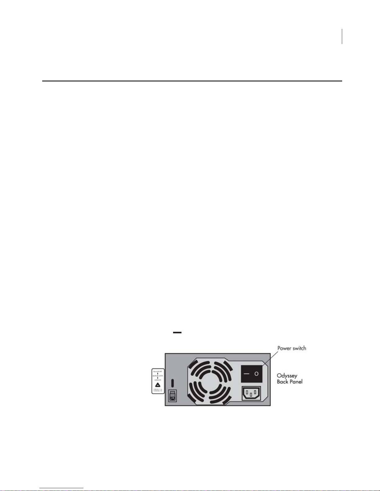
Power Switch
After March 2010, a power switch will be located above the power
cord input. Push ‘ ’ to turn on the instrument or ‘
O
’ to turn it off.

CHAPTER 1
8
Operational Information
Fuse Replacement
Caution:
Replace fuses only with fuses of the specified type and
current ratings.
The power supply fuses are located inside the sealed instrument
power supply, and
are not user serviceable
. If the instrument fails to
power up, and you suspect that a fuse has blown, contact LI-COR
Biosciences or a LI-COR
®
representative. A single 5A fast blow fuse
protecting the Digital Signal Processor (DSP) is located on one of the
printed circuit boards (PCB). This fuse is also not user-serviceable.
The Odyssey
®
Imager requires only minimal maintenance. However,
as with any equipment utilizing electrical voltages, there is a danger
of fire or electrical shock if the equipment is not properly maintained.
LI-COR Biosciences recommends that you routinely inspect the
system and the scanning surface. The following are some general
maintenance guidelines:
•
Wipe all chemical spills from the case and/or scanning surface to prevent
damage to the surface coating.
•
Inspect all cables and power cords for evidence of fraying, exposed wire,
or loose connections.
•
Keep the scanning surface free of organic solvents and other combustibles.
•
Clean the exterior case parts with warm water and a damp cloth. The
exterior case parts are painted with a durable urethane coating that is
resistant to chemical spills. Do not use scouring compounds, solvents such
as acetone, benzene, carbon tetrachlorides, lacquer thinner, or alcohol to
clean the case.
Routine Maintenance

Networking Cables
Multiple Cat. 5 networking cabes are provided with the Odyssey®
Imager. Do not use networking cables other than the ones provided.
The use of other networking cables may result in improper electrical
performance.
9


Chapter 2: Overview and General
Description
Overview
The Odyssey® Imager is a network server device that is connected to
a network, and ultimately to a computer, via TCP/IP. This allows
access to the Odyssey Imager via the Odyssey Application Software
or an Internet browser. The Odyssey Imager can also be connected
directly to the computer in stand-alone (non-network) configurations.
11
Image data, run parameters, and security protocols can be viewed
and/or changed over the network; finished scans are then
downloaded from the Odyssey hard disk to local drives for storage
and analysis.
Note:
Although the Odyssey Imager has an internal hard disk, it should be used for
temporary storage only; when the hard disk is full, the oldest files are overwritten to
make space.
Files can also be erased from the hard disk using the browser
interface; see Chapter 5,
Group
Unique, password-protected User Accounts allow access rights to be
established for multiple users.
.
Viewing and Deleting Scans Within a Scan

CHAPTER 2
12
Odyssey Overview and General Description
Two solid state
diode lasers
simultaneously provide light excitation
at 685 and 785 nm.
Collimating lenses, optical bandpass filters
, and
a
focusing lens
focus and tune the laser beams to produce an
excitation spot on the scanning surface. The microscope electronics
then modulate the laser beams to discriminate the infrared (IR) dye
signal fluorescence from background fluorescence. The scanner
detection optics
focus on the excitation spot and collect light from
the fluorescing IR dyes.
After collection by the
microscope objective
, the light is passed to a
dichroic mirror
. The mirror splits the light and essentially sorts the
fluorescent signals by transmitting the light above 810 nm and
reflecting light below 750 nm. Transmitted and reflected light travels
two independent paths through optics designed to remove scattered
and stray light. The light is ultimately focused onto one of two
avalanche photodiodes
that converts the light to an electrical signal
for processing by the microscope detection electronics.
In the microscope electronics, the signal is amplified, filtered, and
finally converted to a digital value by an analog-to-digital converter.
The digital signal is demodulated, filtered again, and coordinated
with the microscope position by a
Digital Signal Processor
(DSP) to
produce the image file.
The entire compact laser/microscope assembly travels on a platform
that moves beneath the scanning surface (below) along both the
X- and Y-axes.
Hardware Description
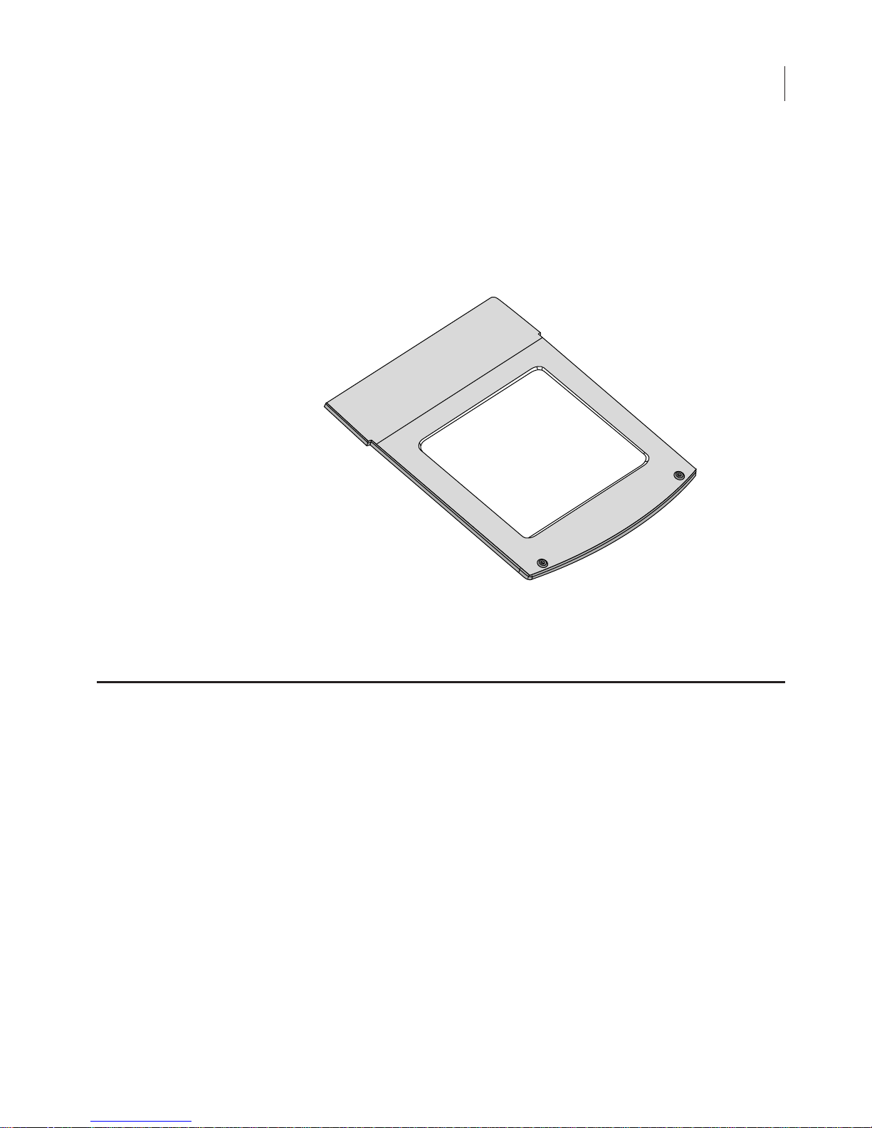
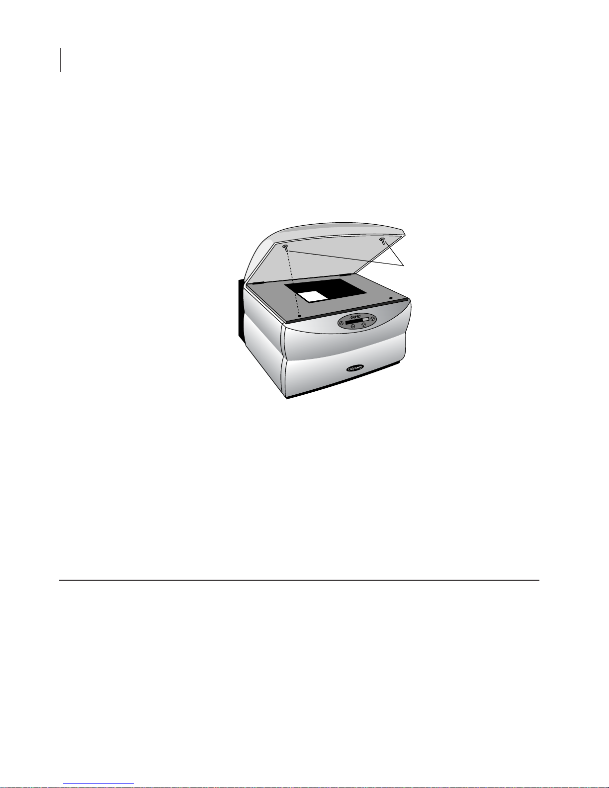
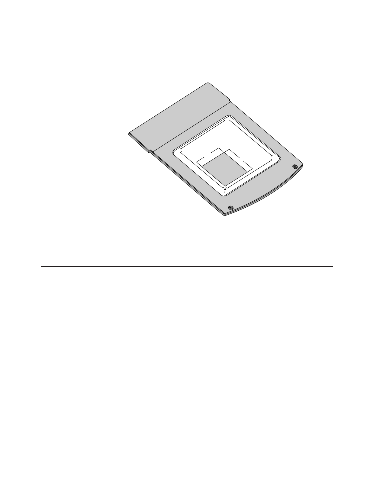
Scanning Surface
The scanning surface is a 25 cm × 25 cm glass plate (below), upon
which the samples to be scanned are placed. The scanning surface is
sealed from the instrument interior so no moisture can penetrate to
the detection optics and electronics below.
Scanning
Surface
13
Figure 2-1. Scanning surface on the Odyssey Imager.
General Description of Scanning
Scans can be initiated in any of three ways; 1) using the Odyssey
Application Software; 2) using an Internet browser, or 3) from the
Odyssey keypad.
®
CHAPTER 2
14
Odyssey Overview and General Description
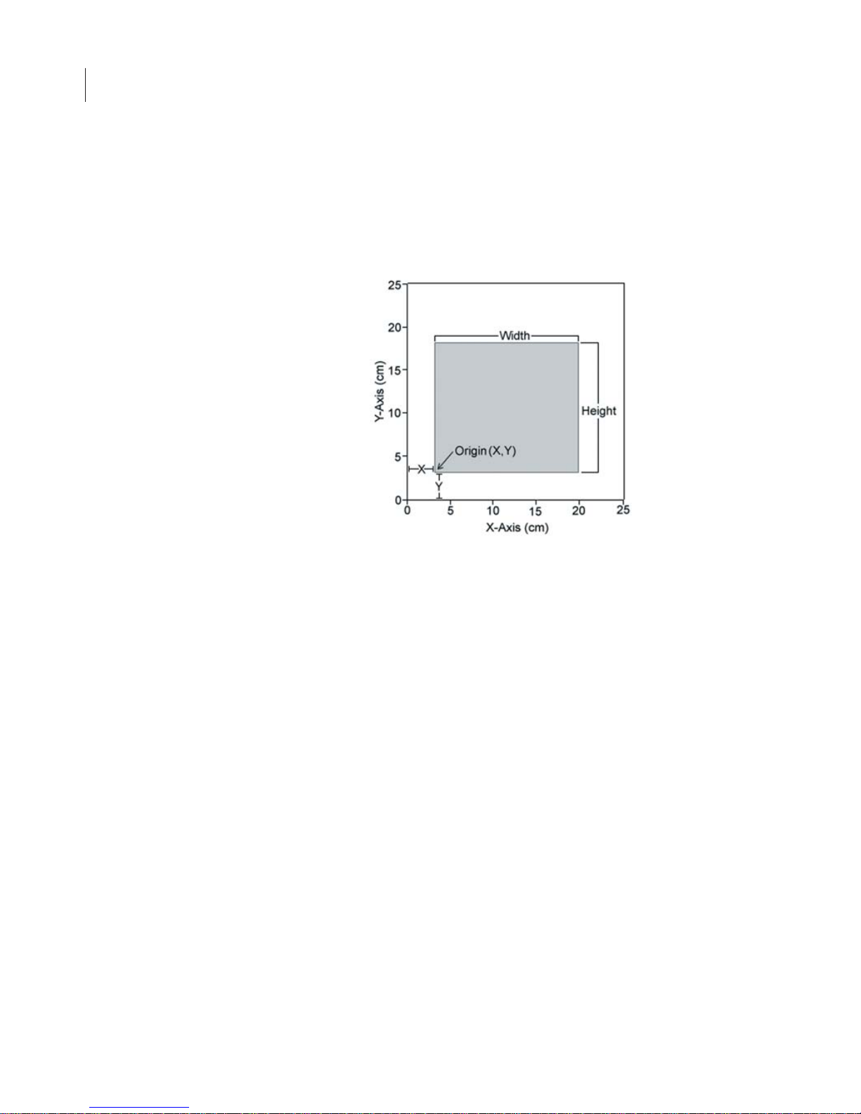
When scanning is initiated from the Odyssey® Application Software
or an Internet browser, the user is presented with a representation of
the scanning surface, from which the origin of the scan and the size
of the area to be scanned are chosen.
Scanning starts at the lower left hand corner of the scanning surface
(when facing the front of the instrument), and progresses first across
the X axis, and then steps up incrementally along the Y axis of the
scanning surface, as shown in Figure 2-3. The scan will again
progress along the X axis until the specified area has been scanned.
Figure 2-2. Scan origin and size of sample are chosen in the software.
15
Figure 2-3. Scans start at the lower left hand corner of the scanning
surface and progresses across the X-axis and up the Y-axis.
Continuous Operation
The Odyssey® Imager and network switch are designed to operate
continuously. During idle times, the Odyssey Imager can remain
powered on or be powered off at your discretion. When idle, the
Odyssey Imager uses approximately 0.5 amp of power, about the
same as a light bulb. If the Odyssey Imager needs to be powered off
(when moving it, for example), see
25
Width
Y-Axis (cm)
Sample
Origin (X,Y)
0
Height
X-Axis (cm)
0
25
Powering Off The System
below.

CHAPTER 2
16
Odyssey Overview and General Description
Note:
After powering off the system, the Odyssey® Imager may take up to 30 minutes
to reboot when power is restored.
Power Button
Briefly press the
Power
button on the front panel keypad to shut
down the Odyssey Imager. You will be asked to confirm that you
want to shut down. Press the
Y (start)
button to shut down.
Shutdown via the Browser Interface
The Odyssey instrument can also be shutdown using the browser
interface as described in Chapter 8. An account with
Administrator
access is required to use the Shutdown function.
Note:
Do not
attempt to turn off the instrument by unplugging the power cable, or by
pushing ‘O’ on the rear power switch (if applicable).
In the event that the front-panel keypad is unresponsive and you
cannot connect to the instrument using an Internet browser, the
instrument can be reset by holding down the
Power
key for at least 4
seconds until the instrument turns off. This procedure cuts power to
the instrument and internal hard disk, so it should only be used when
communication cannot be established by any other means. The
Odyssey instrument should resume normal operation after the
Power
key is pressed again to turn the instrument back on,
though start up
may take several minutes or up to 30 minutes.
Powering Off the System
Resetting the Instrument

Chapter 3: Operation
Before You Begin...
The following procedure is recommended before every scan:
1) Thoroughly wash the glass scanning surface with ultrapure water
and wipe with a lint-free tissue.
2) Repeat the wash with isopropanol to remove any visible smears.
Use ethanol to remove any remaining residues. If dye contamination continues to be a problem, slightly wet a cloth with
acetone and wipe the glass.
contact anything other than the glass. The paint can be damaged
by acetone.
Important:
17
the acetone must not
3) If the silicone mat is being used, rinse it under warm water.
Gentle lab soap may be used, but the soap must be completely
rinsed away before use. The silicone mat may also be rinsed with
isopropanol if needed. Dry the silicone mat with a lint-free tissue.
Cleaning the Scanning Surface
The scanning surface is plate glass, which can be cleaned with any
non-abrasive glass cleaner. Warm, soapy, distilled water or isopropanol can also be used. Do not use scouring compounds or abrasive
scouring pads; the glass can scratch, which can affect the scanned
image.

CHAPTER 3
18
Operation
It is very important that the glass and silicone mat be free of smudges,
dust, and dye before placing membranes or gels onto the Odyssey
®
Imager. Contaminated surfaces in contact with the membrane
surface may cause blotches and streaks that cannot be removed with
further washing.
For Western blotting methods, nitrocellulose or PVDF membranes
may be used (see
www.licor.com
for the latest membranes and kits).
For best performance, pure cast nitrocellulose membranes are
recommended. Detailed blotting protocols can be found in the
Odyssey Application Protocols. There are some general tips,
however, for using membranes with the Odyssey Imager.
•
Do not touch the membrane – handle only with a clean, smooth-edged
forceps. Lift the membrane only by the corners. Fingerprints, even from a
glove, will show clearly when imaged.
•
Use the silicone mat included to cover the membrane(s) before scanning.
Use the 4" soft roller included to remove any air bubbles that may be
present. These optional steps help keep the membrane flat against the
scanning surface for optimum imaging.
•
Protect the membrane from light until it has been scanned.
•
Keep the membrane wet if it is to be stripped and re-used. For Western
blots, store dry or in PBS buffer at 4°C.
•
Use clean containers to avoid cross-contamination and reduce
background.
•
Multiple membranes can be washed together, provided there is ample
volume so each membrane moves freely.
•
If the signal on the membrane is too strong, re-scan at a lower intensity
setting.
•
The fluorescent signal on the membrane will remain stable for several
months or longer if protected from light.
Using Membranes

Using Gels
A protocol for In-Gel Westerns is provided in the Odyssey® Application Protocols manual. Coomassie-stained gels can also be
scanned since Coomassie Blue dye can be seen clearly in the 700 nm
channel, and faintly in the 800 nm channel (see the Western Blot
Analysis protocol for details). As well, nucleic acids stained with
®
Syto
60 and separated in a gel can be imaged in the 700 nm channel
(see the Syto 60 Staining of Nucleic Acids in Gels protocol for more
information). To scan a gel, follow these procedures:
1) Thoroughly rinse the gel with destaining solution or water to
remove dye particulates.
19
2) When placing the gel on the scanning surface, take care not to
trap air bubbles underneath. Cover the gel with plastic wrap to
prevent drying, if desired.
3) Scan the gel in the 700 nm channel.
4) Adjust the focus offset for the gel thickness. The correct focus
offset is 1/2 the thickness of the gel; for a 1 mm gel, set the focus
offset to 0.5 mm. The maximum offset is 4 mm in the most current
edition of the Odyssey Infrared Imaging system, allowing gels of
up to 8 mm to be scanned.
Note:
Early versions of the Odyssey Imager were limited to a 2.0 mm focus offset, but
can be upgraded by installing the Odyssey Server Software version 2.0.0 or above.
5) After removing the gel, clean the glass surface to remove any
residual dye by following the instructions in the section
You Begin...
above.
Before

CHAPTER 3
20
Operation
Microplates that meet certain physical characteristics can be
scanned directly on the Odyssey
®
scanning surface. Proper selection
of microplates significantly affects the results of your analysis as each
plate has its own characteristics including well depth, plate autofluorescence, and well-to-well signal crossover. Some general considerations for microplate selection are provided below.
•
Plate dimensions must be such that the distance from the Odyssey
scanning surface to the target detection area of the plate is 4.0 mm or less.
•
In order to avoid well-to-well signal spread, black-walled, clear bottom
plates should be used for assays that involve imaging of a liquid. Since
In-Cell Western
™
assays use detection at the well surface with no liquid
present, both clear and black-walled plates can be used. Consult protocols
in the Application Protocols manual or on the LI-COR
®
website
(
http://biosupport.licor.com
) for specific recommendations.
•
Do not use plates with white walls because the autofluorescence from the
white surface will create significant noise.
•
For In-Cell Western assays requiring sterile plates for tissue culture growth,
the following plates are recommended by LI-COR Biosciences.
96-well format Nunc
®
(P/N 161093) Clear
96-well format Nunc (P/N 165305) Black
96-well format Falcon
™
(P/N 353075) Clear
96-well format Falcon (P/N 353948) Black
384-well format Nunc (P/N 164688) Clear
384-well format Nunc (P/N 164730) Black
384-well format Falcon (P/N 353961) Clear
384-well format Falcon (P/N 353962) Black
•
Before plate scanning, clean the bottom plate surface with a moist, lintfree paper to remove any obstructions. Additionally, the Odyssey scanning
surface should be thoroughly cleaned using the procedures described
earlier in this chapter.
Using Microplates
 Loading...