

Page 1
FREEDOM SERIES
M400 REEL SYSTEM
Assembly and Operation Instructions
For Solar Covers up to 20’ x 45’ (Max 12 Mil Thickness)
M400 INST 3/03
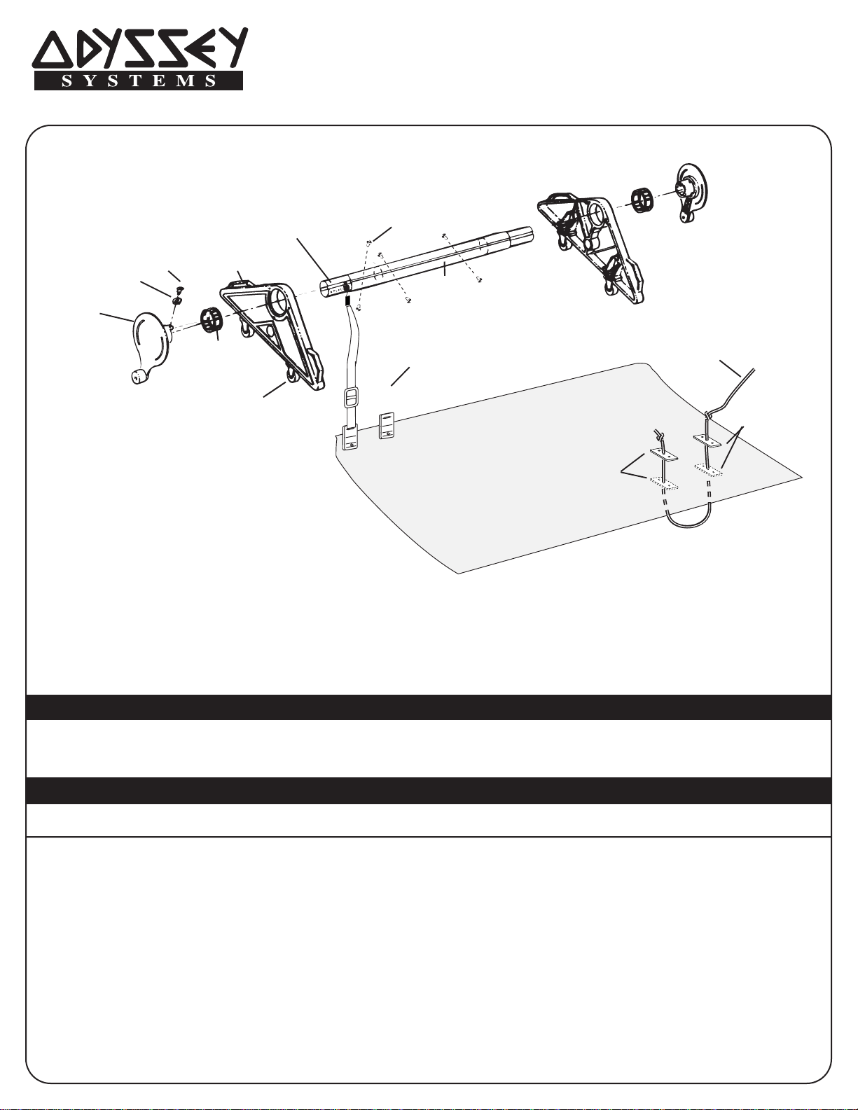
(2.) 4 PLACES
(1.) 2 PLACES
(3.) 4 PLACES
(4.) 2 PLACES
(13.) 2 PLACE
(5.) 2 PLACES
(15.) 4 PLACES
(9.)
(7.)
(6.) 8 PLACES
ATTACHMENT KIT
(8.)
(10.)
INSTRUCTIONS
(14.) 1 PLACE
SEE BLANKET
INSTALLATION
(11.) CORD SET
(12.) 5 FT. CORD
TIE A DOUBLE KNOT
AT BOTH ENDS
(11.) CORD SET
TOOLS REQUIRED
Power Drill Hex Socket Wrench w/ 7/16” hex socket
Drill bits for cutting metal – 1/2” & 13/64” sizes Phillips Screwdriver
PARTS LIST
PARTS DESCRIPTION PART# QTY PARTS DESCRIPTION PART# QTY
1. Handwheel w/handle 523 2
2. 3/4” Nylon Washers 450 4
3. 1-1/4” Phillips Shoulder Bolt 415 4
4. Bearing Race Assembly 615 2
5. Main Frame 504 2
6. Neoprene Tube Insert 475 8
7. Velcro Hook Piece 880 8
9. Strap Buckle 800 8
10. Quick Clip Cover Plate 600 8
11. Cord plate 610 2
12. 5’ Return Cord 840 1
13. 8’6” Aluminium Tube (Inner) 216A 2
14. 8’6” Aluminium Tube (Outer) 217A 1
15. Metal Casters (Wheels) 468 4
8. 6’ Blue Strap 890 8
Page 2
WASHER
HEX HEAD BOLT
OUTER TUBE
INNER
TUBE
NEOPRENE INSERT BODY
HEX HEAD BOLT
NEOPRENE WILL
MUSHROOM AS TIGHTENED
PERFECT
TIGHTNESS
TOO TIGHT
STEP 2
STEP 3
STEP 4
OUTER TUBE
SECTION 2
INNER TUBE
SECTION 1 OR 3
STEP 5
NEOPRENE
INSERT
3”
14”
STEP 4
STEP 2
STEP 3STEP 5
END
VIEW
90°
90°
90°
90°
3”
14”
BEARING RACE
PHILLIPS
SHOULDER
BOLT
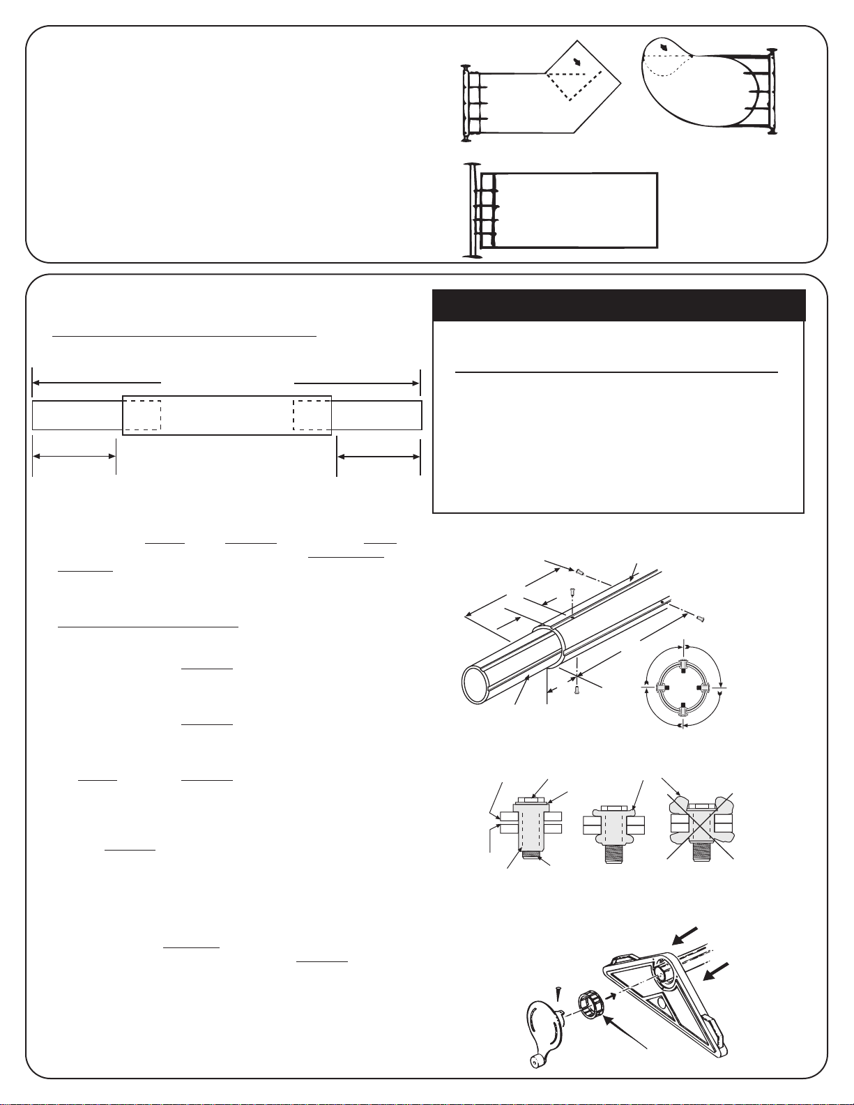
INITIAL PREPARATIONS
SECTION-1
LENGTH-A
SECTION-3
SECTION-2
LENGTH-A
POOL WIDTH + 2 FT.
OVAL WITH EXTENSION
LAZY “L”
RETANGULAR
1. Prior to assembly, select the most suitable location for
the reel, normally 2 ft. from either end of the pool.
However, on irregular pools, a location closer to the
center of the pool may be preferred and at the pools
maximum width. Other considerations are obstructions
(diving boards, handrails, etc). When in doubt, consult
your dealer or call Odyssey for an evaluation of your reel
placement.
2. BLANKET PREPARATION: In order for your solar blanket to
roll up neatly on the solor reel, allow the blanket to relax on
the pool for a day or two and let the heat of the sun iron out
the folds and creases of the blanket.
M400 INST 3/03
ASSEMBLY INSTRUCTIONS
1. Remove all Tube Sections and place on a flat ground as in (FIG. 1).
SECTION 1 IS STORED INSIDE OF SECTION 2. Slide sections 1
and 3 out to the desired total tube length. (Usually pool width plus
two feet). Refer to Table #1 and (FIG. 1).
(FIG. 1)
NOTE: Step 2-9 must be followed
or tube sagging will occur
2. To attach the LEFT SIDE of section 1 & 2 tubes.
Using (FIG. 2), with a power drill and a sharp 1/2” bit, Drill a
hole 3” from the left end
of the groove cut in the tube. Drill through both section 1 and
section 2.
(Refer to Step 2)
3. Place neoprene tube insert into the hole. Using a hex
socket wrench and a 7/16” socket, rotate hex head
two (2) complete turns and stop
4. Rotate tube sections 90° and drill a hole 14” from
the left end of the tube section 2
Repeat all instructions in #3 above.
5. Rotate tube sections 90° and drill a hole 3” from
the
left end
of the tube section 2.
Repeat all instructions in #3 above.
6. Rotate tube sections 90° and drill a hole 14” from
7. Rotate tube sections 90°. Using a hex socket
the left end
Repeat all instructions in #3 above.
of the tube section 2.
wrench and a 7/16” socket, to tighten each hex
head an additional
8. Continue to rotate tubes and tighten hex heads until all are tight
and neoprene insert body mushrooms.
Do not overtighten. (SEE FIG. 3)
9. To attach the RIGHT SIDE of section 2 & 3 tubes.
Repeat instructions #2 thru #8
measurements from the RIGHT END of tube section 2
10. ATTACH RACE AND HANDLE TO TUBE–,Place the main
frames in contact with the pool deck, insert tube through the
center openin. Refer to (FIG. 4)
11. Slide bearing race assembly onto each handwheel and seat in
main frame bushing – center opening. Refer to (Step 7).
of the section 2 tube and in the center
.
(Refer to Step 2)
.
(Refer to Step 3)
(Refer to Step 4)
(Refer to Step 5)
two (2) complete turns.
above, but taking all hole
.
TABLE #1
POOL WIDTH TOT AL TUBE LENGTH A
FEET LENGTH FEET
FEET
14 16’ 4
16 18’ 5
18 20’ 6
20 22’ 7
NOTE: Under no circumstances should the system
be operated if Length A exceeds 9 ft.
Tubes may be cut in size in order to accomadate
smallerpool widths. It is recommended to cut an
equal amount off sections 1 & 3.
(FIG. 2)
(FIG. 3)
(FIG. 4)
STEP 7
Page 3

POOL WIDTH
POOL LENGTH
(FIG. 1)
(FIG. 2)
PUNCH SMALL HOLE
WITH SHARP OBJECT
PUSH SHARP POST
AND SNAP INTO RECEIVER HOLE
3”
POSITION COVER
ON LAST RAISED BAR
ON INSIDE OF CLIP
(FIG. 3)
FOLD AND DISTRIBUTE
8 CLIPS
3”
3”
BUCKLE
CLIP
TO VELCRO
12”
VELRO
24”
INSERT
BUCKLE FROM
THIS END
CLIP POSITION
AND FOLD LINE
12”
(FIG.4)
(FIG. 5)
VELCRO
ON STRAP
VELCRO
ON POLE
IN A STRAIGHT LINE
DOWN THE POLE
(FIG. 6)
VELCRO
ON POLE
M400 INST. 3/03
ASSEMBLY INSTRUCTIONS (Cont.)
12. Rotate each hand wheel until the tab for the screw is at the top position as shown
in STEP 8. Align the keys in the handwheel collar with the corresponding key
ways in the handle and rotate them to make certain that the aluminum tube is
making contact with the back wall of each handle.
13. Using the pre-drilled holes in the hand wheel collar as a guide, drill a
13/64” hole thru each side of the tube. Insert 1-1/4” long Phillips shoulder
bolt thru the nylon washer and into the drilled holes in the aluminum tube
and screw until tight. Repeat these instructions to install hand wheel to
main frame at other end. Refer to Step 8.
MAGNETIC CASTER INSTALLATION
14. Orient the caster assembly as in (Step 9). Magnetic plate should be on the top
and is marked “THIS SIDE UP”. Grip top holding plate and slide magnetic plate
into the slot on the back of the main frame. Using a small hammer, tap the back of
the magnetic plate adjacent to the hinge, alternating right and left side, until the
front of the plate is abutting the main frame and the caster assembly is seated
tightly into slot. Repeat steps for remaining 3 casters. Casters should always be
seated in storage wells until you wish to move the system.
ATTACHING THE COVER FOR IN-GROUND
POOLS
15. The reel system should be positioned at the end of
the pool, perpendicular to the center line of the pool
(SEE FIG. 1). The cover should be on the pool and
properly trimmed.
16. Starting at a point approximately 3” from one edge of
the end of the cover to which the reel will be
connected, attach a plastic cover clip (SEE FIG. 2) to
the cover. The sharp pointed post on the clip will
pierce the cover (or use a knife or other sharp tool
for ease of installation). Continue across the edge of
the cover attaching the remaining seven clips, evenly
spaced. The last clip should be positioned approximately 3” from the opposite edge of the blanket
(SEE FIG. 3).
17. Assembly of strap and buckle: With the ridged
crossbar of the buckle facing up, slide the buckle
onto the strap from the end opposite the Velcro end.
Move the buckle at least 24” up from the end of the
strap (SEE FIG. 4). Feed the end of the strap
through the slot on the plastic clip then thread the
strap end back through the buckle as indicated by
the dotted lines in the diagram. Repeat the process
at each clip position (SEE FIG. 5).
18. Position the Velcro end of the strap as straight as
possible over the tube of the reel system. Place a
Velcro tab on the tube at the Velcro strap end by
removing the protective backing. The tube must be
dry and clean where the Velcro tab is being placed
(SEE FIG. 6). Attach the Velcro end of the strap to
the Velcro tab. Repeat this process in a straight line
along the tube for each of the seven remaining
straps. Using the buckles, adjust each strap so that
each has equal tension on the cover. This is
necessary for proper roll-up alignment. The extra
length should wrap around the tube to facilitate
pulling the blanket off the pool and on to the
tube. The Velcro tabs alone are not strong
enough to pull the blanket up off the pool.
STEP 8
PHILLIPS
SHOULDER BOLT
(2 PLACES)
STEP 9
STORAGE
WELLS
Page 4

POOL COVER
STRAP
TUBE
CLIP
TURN REEL
THIS WAY
VELCRO
T ABS
M400 INST. 3/03
19. For ease of re-covering your pool after use, install the return
cord provided at the opposite end of the pool cover using the
white cord and two sets of male/female cord plates. Locate
the plates about 3” apart and at least 6” from the edge of the
cover (FIG. 7). To install plates, use the plate with three
holes as a guide to punch three holes through the cover. Snap
the posts on the male plate through the two holes on the female
plate with the cover sandwiched between the two plates (FIG. 8).
Thread the return cord through the top center hole of plate #1 and
plate #2 as shown in the diagram and then tie a
double knot at both ends (FIG. 7).
OPERATING INSTRUCTIONS
20. Place the reel system so that it straddles the pool, and is 2 ft from
end of pool as in (FIG. 10). More distance may be required for
irregular pools. If your pool IS NOT rectangular shape, merely
fold the cover in the irregular areas back on itself so that the
entire pool cover can pass between the two end main frames of
the system.
21. Rotate handwheel slowly. The straps will move the cover away
from possible damage on the coping and fold back into itself.
Continued rotation of the handwheel will transport the cover
underneath the tube and then up, over and onto the tube (SEE FIG 9).
In the unlikely event that the Main frame “creeps” during this
operation, use free hand to hold main Frame until the entire cover is
removed from pool. Attempt to keep seams straight and avoid
misalignment.
22. If system has retrieved the cover with ease, you are operating the
system correctly. It is suggested that you mark the position of the
Main frames during operation on the pool decking for future use
of the system.
23. AVAILABLE OPTION: For portability, this system is designed for
the optional Magnetic Caster Assembly Part No. 468
(4 required). See your Odyssey Dealer for details.
MANUFACTURER IS NOT RESPONSIBLE FOR DAMAGE OR
ACCIDENT RESULTING FROM IMPROPER OR
UNSAFE STORAGE OR MOVEMENT
PLACING THE COVER ON THE POOL
24. Roll the reel system to a straddling position 2’ from the
end of the pool, onto the deck marking suggested in
(FIG. 10), lock casters up (if installed) prior to unrolling cover.
25. Hold white return cord and walk down the length of the pool,
allowing the system to “free wheel”
pool surface. Replace folded-back cover into irregularly
shaped areas.
26. Your cover is now installed and operational. If you wish to
remove the reel system from the pool while the
cover is on the pool, detach the straps using the lift-off
velcro tabs (SEE FIG. 10), and roll empty system to
storage area.
SOME HELPFUL HINTS
1. Make sure the cover is not dragging against the side of the pool
coping.
2. If tube is sagging: refer to assembly instruction on drilling tubing
and tighten neoprene inserts.
3. If tubes discolors, they can be restored using Flitz metal polish
available at hardware/marine stores.
4. Place a white protective cover over blanket and secure to protect
blanket from the sun when rolled up.
5. Do not use lubricants on any plastic parts.
6. Remove handwheels at the beginning of each season, or every 12
7. Always store the reel with an eye for safety.
months. Clean yoke bushing, bearing race, and end cap with
warm soapy water. Rinse, dry and reassemble.
the cover back onto the
(FIG. 7)
PLATE #1
TIE DOUBLE KNOT
AT BOTH ENDS OF CORD
3”
PLATE #2
6”
(FIG. 8)
SNAP TOGETHER
PUNCH 3 HOLES WITH
SHARP INSTRUMENT
FIG. 9
FIG. 10
POOL
COVER
STRAPS
LIMITED WARRANTY
ODYSSEY warrants the reel system to be free of
workmanship/material defects for a period of
three (3) years from the date of purchase. Any
claims must be supported by invoice/proof of
purchase.
EXCLUDED FROM THIS WARRANTYARE ALL
CONSUMABLES: straps, cord, velcro, plastic
plates and clips.
ODYSSEY WILL not be liable for any incidental
or consequential damages resulting from any
defects in workmanship or material, nor for personal injury resulting from improper placement of
reel system when not in use.
ODYSSEY SYSTEMS
220 South Ola Vista, Suite C, San Clemente, CA 92672
(949) 498-9454 • Fax (949) 361-0608
www.odysseysystems.com
© ODYSSEY SYSTEMS 2003
2 FT
POOL END
 Loading...