

Odyssey CT80-250, CT80.3F9A1, CT120.3G9A, CT215.1H9A, CT80.3P9A1 Installation And Operation Instructions Manual
...
Odyssey
Danger Sign: Indicates a hazardous situation which, if not avoided, will result in
Warning Sign: Indicates a hazardous situation which, if not avoided, could result
bol: Indicates a hazardous situation which, if
Caution Sign without Safety Alert Symbol: Indicates a hazardous situation
es a hazardous situation which, if not avoided, could result
H
Model Numbers: CT80-250
Version Date: 2013-03-15
NEW – OUTDOOR SENSOR
Meets Sept. 2012 requirements for
“Automatic Means”
INSTALLATION AND OPERATION INSTRUCTIONS
ODYSSEY OIL BOILER
Venting Applications: Natural Draft or Direct Vent (Balanced Flue)
TABLE OF CONTENTS
1.0 INTRODUCTION...............................................................................................................3
2.0 SPECIFICATIONS..............................................................................................................6
3.0 BOILER LOCATION..........................................................................................................8
4.0 BOILER ASSEMBLY.........................................................................................................9
5.0 GENERAL VENTING......................................................................................................14
6.0 NATURAL DRAFT APPLICATIONS.............................................................................15
7.0 DIRECT VENT APPLICATIONS....................................................................................19
8.0 BOILER PIPING...............................................................................................................26
9.0 FIELD WIRING................................................................................................................28
10.0 INSTALLATION CHECKLIST .......................................................................................34
11.0 ANNUAL MAINTENANCE AND INSPECTION ..........................................................36
12.0 PARTS LIST .....................................................................................................................39
13.0 WARRANTY....................................................................................................................43
Odyssey CT80-250
HAZARD SYMBOLS AND DEFINITIONS
serious injury or death.
in serious injury or death.
Caution Sign plus Safety Alert Sym
not avoided, could result in minor or moderate injury.
which, if not avoided, could result in property damage.
Notice Sign: Indicat
in property damage.
This Boiler must be installed by a licensed and trained Heating Technician or
the Warranty is Void. Failure to properly install this unit may result in
property damage, serious injury to occupants, or possibly death.
NTI # 84944
Odyssey
Read Before Proceeding
│
Installation and Operation Instructions CT80-250
If you do not follow these instructions exactly, a fire may result causing property
damage, serious injury or death.
FOR YOUR SAFETY, READ BEFORE OPERATING_
BEFORE OPERATING:
A. Do not start burner unless the smoke hood, clean out door, HydroStat 3250, flue breeching, and burner
door (if applicable) are secured in place and the boiler is filled with water.
B. Do not attempt to starter burner when excess oil has accumulated in combustion chamber, when unit is
full of vapour, or when combustion chamber is very hot.
C. Do not use gasoline, crankcase drainings, or any oil containing gasoline.
D. Never burn garbage or paper in the unit and never leave combustible material around it.
E. Always keep the oil supply valve shut off if the burner is shut down for an extended period of time.
F. Do not tamper with the unit or controls - call your service personnel for service and maintenance.
G. Do not use this boiler if any part has been under water. Immediately call a qualified service technician to
inspect the
under water.
boiler and to replace any part of the
OPERATING INSTRUCTIONS_
control system and any oil control which has been
1. STOP! Read the safety information above very carefully.
2. Initial start-up and start-ups after periods of extended/seasonal shutdown must be performed by a
qualified service technician.
3. Check the boiler area for proper clearances.
4. Turn the thermostat(s) up.
5. Turn the emergency power isolation switch on.
6. If ignition does not occur, follow the instructions “To Turn Off Oil Boiler” and call a qualified service
technician.
TO TURN OFF OIL BOILER_
1. STOP! Read the safety information above very carefully.
2. Turn off emergency power isolation switch. Should be mounted on the wall near entrance to boiler room.
Void Warranty - This boiler must have water in it whenever the burner is on or it will
damage the unit and void the warranty. Failure to follow these instructions may result in
serious injury or death.
Fuel Oil - Use only No. 2 fuel oil for boiler models listed in this manual. Failure to follow
these instructions may result in severe personal injury, property damage, or death.
Low Water Cut Off (LWCO) - To take advantage of the HydroStat’s LWCO feature, the
Odyssey is equipped with a special immersion well call the Electro-well™. Failure to use
the Electro-well™ provided with the boiler will over-ride the LWCO feature and allow the boiler to operate
during low water conditions which may result in over heating, fire, serious injury, or death.
Oil Supply Valve - Always keep the oil supply valve shut off if the burner is shut down
for an extended period of time.
2

CT80-250 Introduction - Installation & Operation Instructions
1.0 INTRODUCTION
│
Odyssey
General Installation Requirements
The installation of your NTI Odyssey oil boiler shall be in accordance with these instructions and the regulations
of the authorities having jurisdiction and must comply with the following codes and standards:
United States
State and local plumbing, heating, and electrical codes
NFPA 70 National Electric Code
NFPA 31 Installation Code for Oil Burning Equipment
Standard ANSI/ASME CSD-1, Controls and Safety Devices for Automatically Fired Boilers (if applicable)
Canada
Provincial and local plumbing, heating, and electrical codes
CSA C22.1 Canadian Electrical Code Part One
CSA B139 Installation Code for Oil Burning Equipment
The Odyssey is a knock-down boiler constructed of cast iron. The venting application needs to be decided in
advance, either Natural Draft or Direct Vent, prior to ordering the boiler as burner packages will vary depending
on the venting application. The boiler package comes in three sections and requires field assembly. Check your
boiler package when it arrives and ensure it includes the following:
1. Boiler
2. Jacket
3. Burner Kit
This document pertains to the correct installation and operation of NTI Odyssey oil boilers for Natural Draft and
Direct Vent models. The instructions detailed in this document supersede any and all previous instructions
provided by NTI, written or otherwise. The warranty is included in the Installation and Operation manual. Each
unit comes complete with the following documentation:
1. Installation and Operating Instructions
2. Users Manual
Read and understand this entire document prior to proceeding with the installation of the
Odyssey. Failure to follow the instructions outlined in this document will result in
property damage, serious injury or death.
User Responsibilities
This boiler must be installed and serviced by a qualified installer or service technician. This boiler must be
serviced and inspected annually. As the User/Owner of this equipment, you are responsible for ensuring the
maintenance is performed at the required intervals. See “Users Manual”.
Failure to have the boiler properly serviced and inspected on a regular basis by a qualified
service technician may result in property damage, serious injury or death.
Installer Responsibilities
As the installing technician it is your responsibility to ensure the installation is performed in accordance with this
instruction manual as well as any applicable local or National installation codes. It is also your responsibility to
inform the User/Owner of their obligation with respect to the above description under “User Responsibilities”.
Failure to follow this warning could result in fire, serious injury, or death.
3

Odyssey
Natural Draft Applications
│
Installation and Operation Instructions - Introduction CT80-250
Natural Draft Applications - All Odyssey models are certified as Natural Draft boilers
which require a “Chimney System”. The exhaust gases must be vented directly to the
chimney. Failure to follow these instructions will result in serious injury or death.
Blocked Vent Switch - All Natural Draft Odyssey boilers require a Blocked Vent Switch
which is factory supplied and packaged with the burner kit and is mandatory in Canada.
The Block Vent Switch must be field installed as per the instructions in this manual and the manufacturers
instructions included with the switch. Failure to follow the specified instructions may result in fire, property
damage, personal injury, or death.
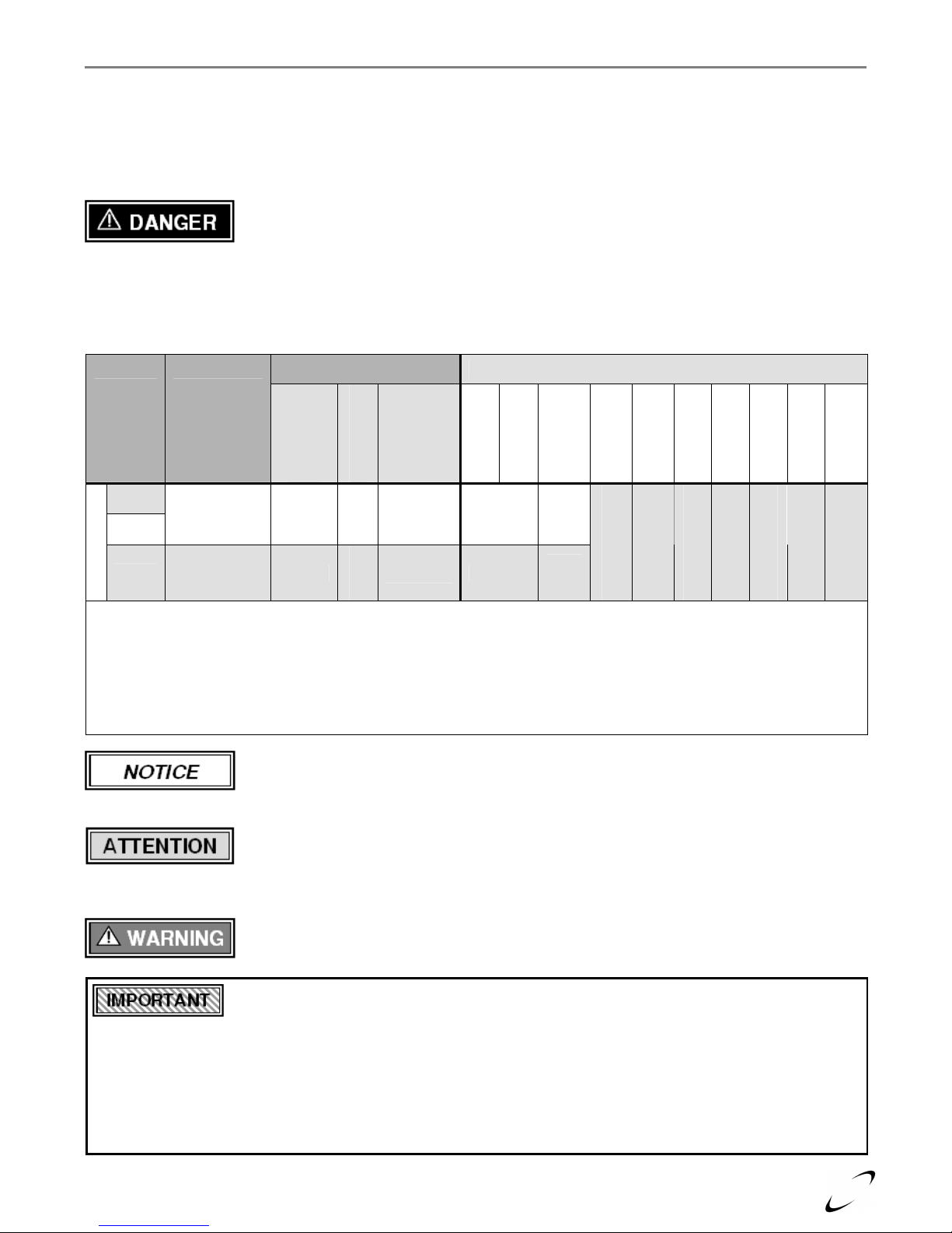
Table 1-1 Odyssey Boiler Packages (Natural Draft)
MODEL
4
CT80
4
CT90
4
CT100
BOILER PACKAGE
BOILER
PART
NUMBER
Boiler
CT80.3F9A1 CT80
Burner Kit
Jacket
Natural
Draft 1
Only
Burner
82002
F3.CT
10618
Burner Kit Contents (Natural Draft)
2
Blast Tube
Nozzle
HydroStat
3250
Hydrolevel
0.65
o
60
84024
W
Tridicator
Electro-Well
OD Sensor
Relief Valve
Supply Tee
Block Vent
CT120
84654
0.85
60oB
1.5
60o W
0.75
70oB
84787
84788
81342
83604
13701
84829
CT150
CT180
Riello Burner
CT215
CT230
CT250
CT80
CT90
CT100
CT120.3G9A
1
4
CT215.1H9A1 CT215
4
4
CT80.3P9A1 CT80
4
CT120
F5.CT
3
10630
82003
F10.CT
82004
NYC601CT 81031
10632
82002
CT120
CT150
CT180
Becket Burner
CT215
CT230
CT120.3P9A1
4
CT215.3P9A1 CT215
CT120
CT250
Notes:
1
Boiler manual packaged with the Burner Kit.
2
Nozzle size included in Burner Kit. See below, “Attention: Nozzle Sizes”.
3
Burner and blast tube comes assembled c/w nozzle specified in this table. Nozzle may need to be changed depending on boiler output.
4
Models CT80-100 and CT180 are no longer offered as they do not meet new minimum efficiency regulations.
NYC602C
T
82003
NYC602C
T
82004
81032
81032
1.10
60oB
1.10
60oB
Nozzle Sizes - The nozzle sent with each respective boiler burner kit is for the minimum
firing rate specified for that burner. To obtain a different firing rate, replace the factory
supplied nozzle with the appropriate nozzle that meets the desired output. Refer to Tables 2-1 to 2-2 in Section
2.0 for nozzle specifications and performance ratings for Natural Draft boilers.
Manufacturer’s Instructions - For complete instructions on installation and control
operations, refer to the manufacturer’s instructions included with the Fuel Smart
HydroStat 3250, Burner Package, and Blocked Vent Switch.
Switch
82905
4
CT10
0
CT80-250 Introduction - Installation & Operation Instructions
│
Odyssey
Direct Vent Applications
There are four Odyssey models, CT90-120, certified for installation as a Direct Vent boiler. This balanced flue
system requires a special venting system in order to pressurize and essentially equalize the inlet and outlet
pressure to ensure normal operation. Refer to section “General Venting” and “Specifications” for more details on
Direct Vent applications and termination kits.
Balanced Flue Applications - Models CT90-120 are also certified as Direct Vent boilers
and must be ordered as such. Balance flue systems must use the NTI approved venting
system. Note that the Direct Vent Terminal and Insulated Flex Pipe are sold separately (see Table 7-2 Direct
Vent Kit Components for more details). This “Special Venting System” is designed for pressurized venting with
NTI Direct Vent boilers. The exhaust gases must be piped directly to the outdoors using the vent materials and
rules outlined in these instructions. Failure to follow these instructions will result in serious injury or death.
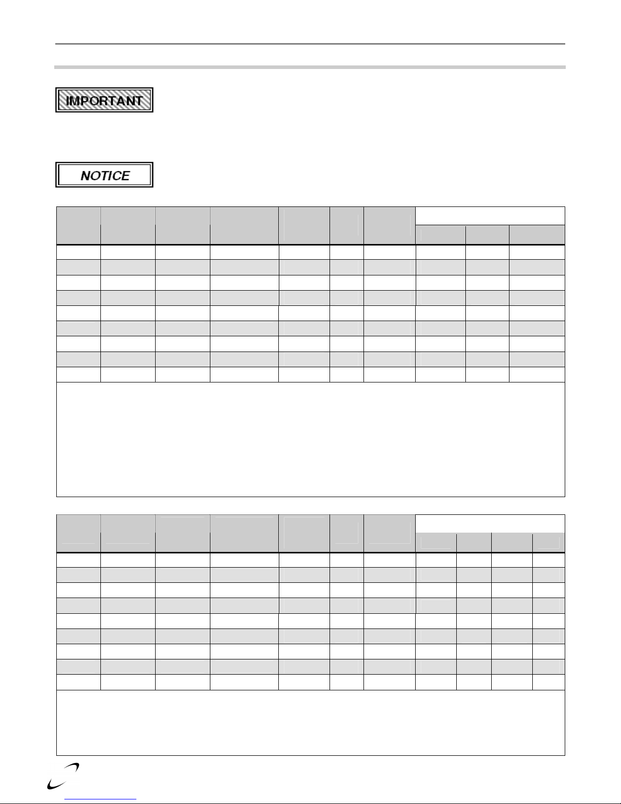
Table 1-2 Odyssey Boiler Packages (Direct Vent)
BOILER PACKAGE
Burner Kit Contents (Direct Vent)
Jacket
82002
82003
Burner
Kit
Direct
Vent
BF5.CT
BF5.CT
2
1
3
3
Burner
Blast Tube
Nozzle
HydroStat
3250
Hydrolevel
Electro-Well
Tridicator
OD Sensor
Relief Valve
81122
81122
0.85
60oB
0.85
60oB
84787
84788
81342
83604
13701
4
Supply Tee
Direct Vent
84829
Table 7-2
BOILER
MODEL
CT90
PART
NUMBER
6
Only
Boiler
CT90.3T9A4 CT80
6
CT120
Riello Burner
Notes:
1
Boiler manual packaged with the Burner Kit.
2
Nozzle size included in the Burner Kit. See below, “Attention: Nozzle Sizes”.
3
Burner and blast tube comes assembled c/w nozzle specified in this table. Nozzle may need to be changed depending on boiler output.
4
Direct Vent Terminal not included in Kit. Refer to Table 7-2 for a list of components that must be ordered separately.
5
Riello BF5 burners are single line gravity feed. See burner manufacturers’ instructions for more details.
6
Models CT80-100 are no longer offered as they do not meet new minimum efficiency regulations.
CT120.3T9A4 CT120
Manufacturer’s Instructions - For complete instructions on installation and control
operations, refer to the manufacturer’s instructions included with the Fuel Smart
HydroStat 3250, Burner Package, and Direct Vent Terminal.
Nozzle Sizes - The nozzle sent with each respective boiler burner kit is for the minimum
firing rate specified for that burner. To obtain a different firing rate, replace the factory
supplied nozzle with the appropriate nozzle that meets the desired output. Refer to Table 2-3 in Section 2.0 for
nozzle specifications and performance ratings for Direct Vent boilers.
Intakes/Vents - Failure to keep the Vent and Combustion Air Intake clear of ice, snow,
and other debris may result in property damage, serious injury, or death.
which is provided primarily to permit the use of an external energy management system that serves the same function.
THIS OVERRIDE MUST NOT BE USED UNLESS AT LEAST ONE OF THE FOLLOWING CONDITIONS IS TRUE :
An external energy management system is installed that reduces the boiler water temperature as the heating load
decreases.
This boiler is not used for any space heating.
This boiler is part of a modular or multiple boiler system having a total input of 300,000 BTU/hr or greater.
This boiler is equipped with a tankless coil.
Energy Saving Feature - This boiler is equipped with a feature that saves energy by reducing the
boiler water temperature as the heating load decreases. This feature is equipped with an override
Kit
5
Odyssey
2.0 SPECIFICATIONS
Natural Draft Application
│
Installation and Operation Instructions - Specifications CT80-250
Draft Settings (Natural Draft) - The Odyssey is designed to operate with -.03” w.c. draft
in the flue breaching. For proper operation, there must be enough natural or mechanical
draft. Due to the design of the Odyssey, it may operate at a positive over fire pressure up to +.20 at -.03 draft. Due
to installation and equipment variations, recommended air settings are a guideline and will require alteration. See
Tables 2-1 and 2-2.
Insertion Depth (Natural Draft) - See General Notes section in Tables 2-1 and 2-2.
Table 2-1 Riello Burners with Odyssey Boilers (Natural Draft)
Boiler
Model
CT80
CT90
CT100
8
8
Input
GPH (US)
0.65 77 67
0.75 88 77
8
0.85 99 86
CT120 1.00 121 105
CT150 1.25 149 130
8
CT180
1.50 176 153
CT215 1.75 212 184
CT230 1.85 223 194
CT250 2.00 240 209
General Notes:
1
Output is “Heating capacity” for models CT80-250.
2
Models CT80-250 use Riello 40 series burners.
3
Energy ratings for C85-250 have been confirmed by AHRI.
4
Models C80-100 - F3 burners have an insertion depth of 2.375”.
5
Models C120-180 - F5 burners come assembled with an insertion depth of 2.375”.
6
Models C215-250 - F10 burners have an insertion depth of 2.75”.
7
F10 burner heads - If head carbons on models CT215-250, reduce turbulator setting and increase air a little.
8
Models CT80-100 and CT180 are no longer offered as they do not meet new minimum efficiency regulations.
Table 2-2 Beckett Burners with Odyssey Boilers (Natural Draft)
Boiler
Model
CT80
CT90
CT100
4
4
Input
GPH (US)
0.65 77 67
0.75 88 77
4
0.85 99 86
CT120 1.00 121 105
CT150 1.25 149 130
4
CT180
1.50 176 153
CT215 1.75 212 184
CT230 1.85 223 194
CT250 2.00 240 209
General Notes:
1
Models CT80-250 use Beckett AFG50 series burners.
2
Energy ratings for C85-250 have been confirmed by AHRI.
3
Models CT80-250 - MDL1 (NYC601) burners and MDV1 (NYC602) have an insertion depth of 3.75.
4
Models CT80-100 and CT180 are no longer offered as they do not meet new minimum efficiency regulations.
Heating
Capacity
MBH
Heating
Capacity
MBH
Net I=B=R
Rating Water
MBH
Net I=B=R
Rating Water
MBH
AFUE
Efficiency
%
83.6% 117
Pump
PSIG
Delevan
Nozzle
0.60 60oW
83.0% 133 0.65 60oW
82.4% 128 0.75 60oW
85.1% 138 0.85 60oW
84.0% 156 1.00 60oW
82.8% 144 1.25 60oW
85.8% 136 1.50 60oW
85.5% 152 1.50 60oW
85.0% 178 1.50 60oW
AFUE
Efficiency
%
83.6% 117
83.0% 133 0.65 60oW
82.4% 128 0.75 60oW
85.1% 138 0.85 60oW
84.0% 156 1.00 60oW
82.8% 144 1.25 60oW
85.8% 136 1.50 60oW
85.5% 152 1.50 60oW
85.0% 178 1.50 60oW
Pump
PSIG
Delevan
Nozzle
0.60 60oW
Recommended Burner Settings
Burner Air Turbulator
F3 5 0
F3 7 0
F3 7 2
F5 3 2
F5 5 2
F5 9 3.5
F10
F10
3.5
7
2
2
F10 6 3
Recommended Burner Settings
Burner
MBL1
MBL1
MBL1
MDV1
MDV1
MDV1
MDV1
MDV1
MDV1
Head Shutter
- 5 0.5
- 6 1
- 10 0
0 5 1
1 6 2
2 8 3
3 10 6
4 10 5
4 8 7
Band
6

CT80-250 Specifications - Installation & Operation Instructions
Direct Vent Application
│
Odyssey
Draft Settings (Direct Vent) - Due to the design of the balanced flue system, the Odyssey
will operate at a positive draft pressure and a positive over fire pressure at all times. It is
designed to operate with a maximum stack draft of 0.25” w.c. and a maximum over fire draft of 0.33” w.c. when
little or no wind is present. In extreme wind conditions, the maximum stack draft is 0.35” w.c. and the maximum
over fire draft is 0.45” w.c. Due to installation and equipment variations, recommended air settings are a guideline
and will require alteration. See Table 2-3.
Insertion Depth (Direct Vent) - See General Notes section in Table 2-3.
Table 2-3 Riello Burners with Odyssey Boilers (Direct Vent)
Boiler
Model
CT90
CT100
4
4
Input
GPH (US)
0.75 88 77
0.85 99 86
CT120 1.00 121 105
General Notes:
1
Models CT90-120 use Riello 40 series burners.
2
Energy ratings for CT90-120 have been confirmed by AHRI.
3
Models CT90-120 - BF5 burners come assembled with an insertion depth of 2.375”.
4
Models CT80-100 are no longer offered as they do not meet new minimum efficiency regulations.
Heating
Capacity
MBH
Net I=B=R
Rating Water
MBH
AFUE
Efficiency
%
83.0% 133
82.4% 128
85.1% 138
Pump
PSIG
Delevan
Nozzle
0.65 60oW
0.75 60oW
0.85 60oW
Recommended Burner Settings
Model Air Turbulator
BF5 4
BF5
BF5
5
6
0
0
1.5
Boiler Characteristics
Table 2-4 Odyssey Boiler Characteristics
Description
CT80-100 CT120-180 C215-250
Boiler Shell Weight [lbs] 260 390 500
Fuel Type No. 2 Oil
Water Connections – NPT [in.] 1.25 1.25 1.25
Dimensions H x W x D [in.]
Approx. Boiler Weight with Water [lbs]
Approx. Boiler Water Content [usg]
Stack Size
Electrical Rating
30 x 17.5 x 15.5 30 x 25.5 x 15.5 30 x 33.5 x 15.5
290 435 560
3.6 5.4 7.3
5 5 5
120V / 1Ph / 60Hz / < 12A
Boiler Shell
7
1, 2
Odyssey
3.0 BOILER LOCATION
│
Installation and Operation Instructions - Boiler Location CT80-250
In all cases, the Odyssey must be installed indoors in a dry location where the ambient temperature must be
maintained above freezing and below 100°F [38°C]. All boiler components must be protected from dripping,
spraying water, or rain during operation and servicing. Consider the proximity to the following when
determining the best boiler location.
System Water Piping
Oil Supply
Electrical Power
Combustion Air / Ventilation Air
Chimney
Components - Water or flood damaged components must be replaced immediately with
new components (see parts list). Failure to do so may result in fire, serious injury, or death.
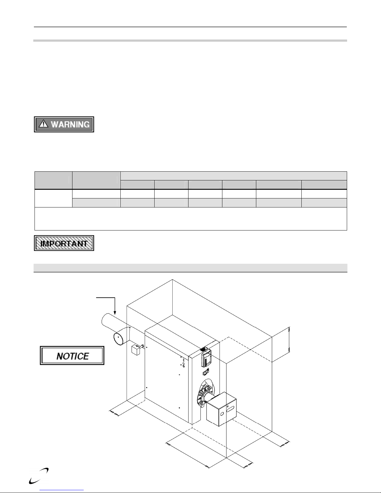
Clearances - Clearances to combustibles represent the minimum clearances required for safety and service.
Recommended clearances are for ease of piping installation, annual maintenance, and service access. Refer to
Table 3-1 and Figure 3-1.
Table 3-1 Minimum Clearances for Installation and Service
Model Clearances
CT80-250
Notes:
1
Minimum clearances from flue pipe to combustibles is 9” for single-wall pipe; 6” for double-wall pipe (Type-L).
2
Flue pipe clearances take precedence over all other clearances.
To Combustibles 24 [610] 5 [124] 12 [305] 5 [124] 9 [228] Combustible
Recommended 36 [915] 24 [610] 24 [610] 24 [610] 9 [228] Combustible
Front Rear Top Sides
Dimensions - inches [mm]
Flue Pipe
Floor
Boiler Location - Even if all installation codes are met, good judgment and common
sense must also be used when selecting a boiler location. Refer to minimum clearances in
Table 3-1 and vent clearances for chimney or direct vent applications.
Figure 3-1 Minimum Clearances to Combustibles
Flue Pipe
9” minimum
Flue pipe clearances
take precedence over
all clearances, refer to
Table 3-1.
Rear 5”
8
Top 12”
Right Side 5”
Front 24”
Left Side 5”
nuts and washers at
the rear of the boiler
C 85-340 Boiler Assembly - Installation & Operation Instructions
4.0 BOILER ASSEMBLY
│
Odyssey
The installation of the boiler shall be in accordance with the authorities having jurisdiction and must comply with
Standard CSA B139 (Canada) or NFPA 31 (USA).
Fiberglass Materials - Before installing the insulation, read “Handling Instructions” in
Section 11.0 and the protective measures recommended when handling fiberglass.
Assembly Procedure
The boiler assembly procedure is to be completed in sequence and in conjunction with the illustrated assembly
diagrams, Figures 4-1 through 4-12.
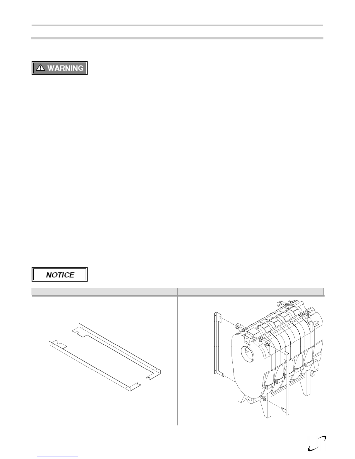
1. Do not fully tighten screws until jacket assembly is complete.
2. Level the boiler before commencing jacket installation.
3. Install rear brackets on the boiler, secure by tightening nuts (Figures 4-1 to 4-3).
4. Install front brackets on the boiler, secure by tightening nuts (Figures 4-4 to 4-6).
5. Install fiberglass insulation on the boiler by wrapping it around the heat exchanger. Secure with factory
supplied twine (Figure 4-7).
6. Remove all protective plastic film on the jacket panels before installing.
7. Attach side panels to front and back brackets (Figure 4-8).
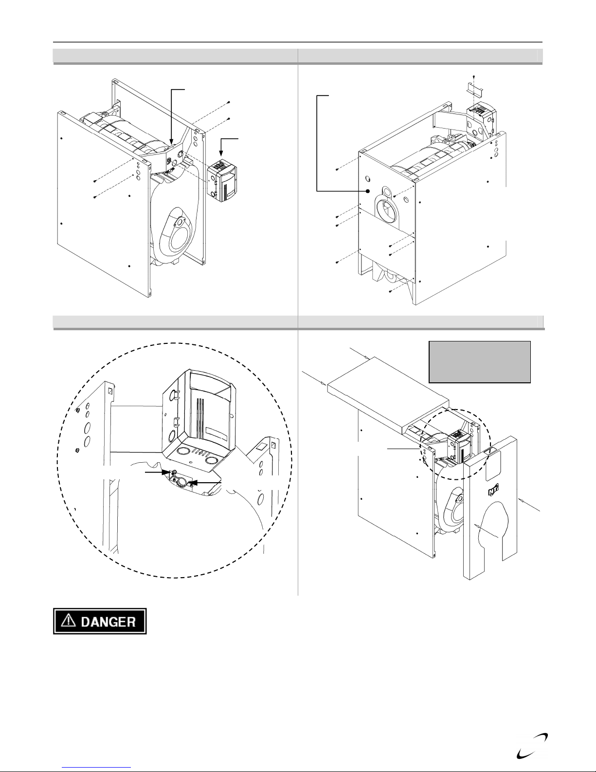
8. Install control panel between side panels, secure with screws provided (Figure 4-9).
9. Mount HydroStat 3250 by sliding it down over the tabs on the control panel. Secure in place with hold down
bracket as shown (Figure 4-10).
10. Mount bottom back panel to boiler (Figure 4-10); Recommend installing top back panel after flue breeching
connected, sealed, and supported. (See also Figure 6-1 Flue Breeching).
11. Fully tighten all jacket screws to secure panels in place.
12.
Insert sensor fully into the Electro-well or boiler overheating may occur (Figure 4-11). See “Danger”
warning on page 11.
13. Feed the green wire, connected to the boiler ground screw, through the knockout in the back of the HydroStat.
Connect the other end of the wire to the HydroStat ground screw inside the control (green screw).
14. Installation of burner and completion of wiring must be done with front cover removed.
15. Install top cover. Align the top panel clips into the slots in the top of the side panels and slide cover forward
to lock clips in place (Figure 4-12).
HydroStat 3250 Instructions - For complete installation and operation instructions, refer
to the manufacturer’s instructions included with the Fuel Smart HydroStat 3250.
Figure 4-1 Rear Brackets Figure 4-2 Mount Rear Brackets
Top
Bottom
Slide the rear
brackets behind the
as shown.
9
Tighten the nuts,
Before installing the insulation, read the
Remove protective
plastic coating from
Odyssey
│
Installation and Operation Instructions - General Venting CT80-250
Figure 4-3 Tighten Bracket Nuts (Rear) Figure 4-4 Front Brackets
Tighten nuts, top and bottom,
to secure the rear brackets to
the boiler.
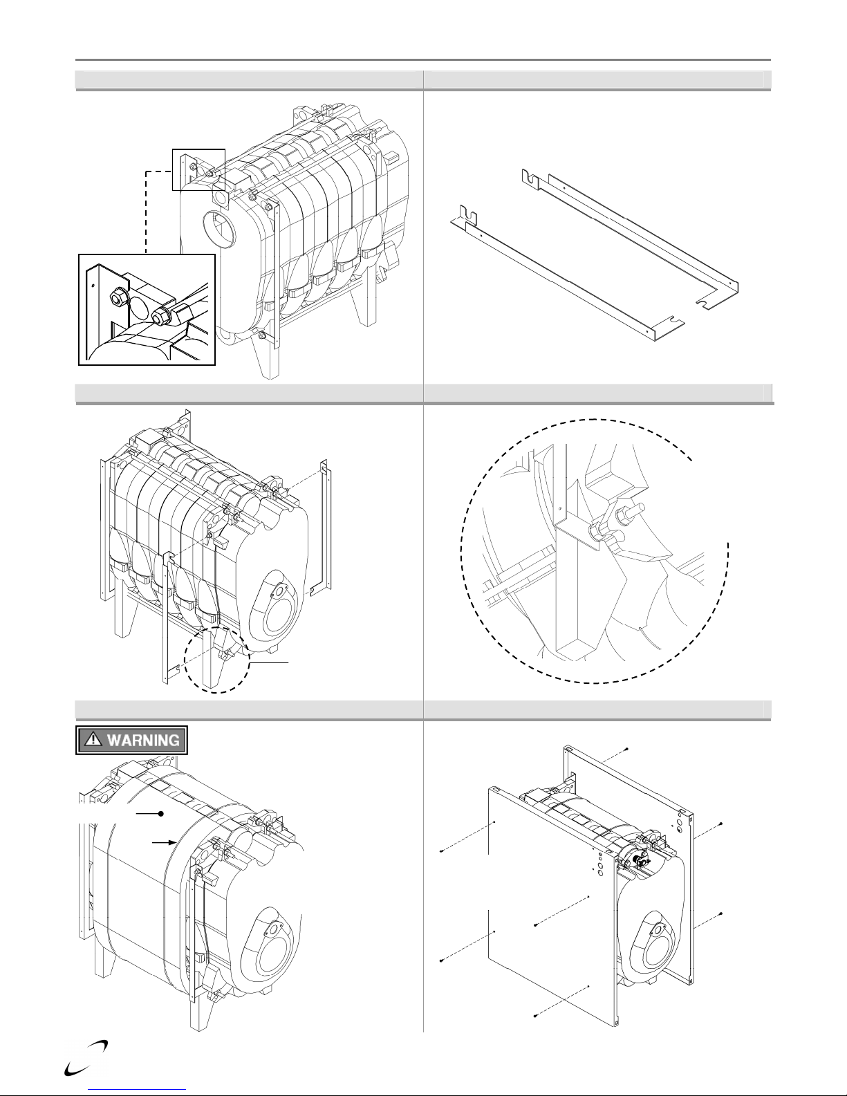
Figure 4-5 Mount Front Brackets Figure 4-6 Tighten Bracket Nuts (Front)
Top
Bottom
Slide the front brackets
behind the nuts and washers
at the front of the boiler.
Insulation
Twine
top and bottom,
to secure the
front brackets to
the boiler.
See Figure 4-6
Figure 4-7 Insulate Heat Exchanger Figure 4-8 Attach Side Panels To Brackets
“Handling Instructions” in Section 11.0.
all jacket pieces
before installing.
Install insulation around
the heat exchanger and
secure in place with
factory supplied twine.
Attach both side panels
to brackets using sheet
metal screws provided.
10
C 85-340 Boiler Assembly - Installation & Operation Instructions
side panels, secure
the HydroStat 3250
to the control panel
Secure bottom back panel.
Ground Wire
- Connect green
wire between ground screw
Installation of burner and
Figure 4-9 Attach HydroStat 3250 Bracket Figure 4-10 Attach Back Panels & Electro-well
│
Odyssey
Control Panel
Recommend installing
top back after flue
breeching connected
and sealed.
Hold Down
Bracket
HydroStat
3250
Attach hold down bracket
Attach the control
panel between the
as shown.
Figure 4-11 Install Ground Wire and Sensor Figure 4-12 Install Top and Front Covers
to top edge of HydroStat
control panel to secure it
in place.
completion of wiring
must be done with front
cover removed.
See Figure 4 -11
Ground Screw
Electro-well
and HydroStat ground screw.
Sensor - Insert fully into the
Electro-well or overheating
may occur. See “Danger”.
Sensor - Insert the sensor fully into the Electro-well or the boiler may overheat resulting
in fire, property damage, serious injury, or death.
11
Odyssey
│
Installation and Operation Instructions - General Venting CT80-250
Burner Installation
The Odyssey boiler is designed to work with burners described in this manual. The use of other nozzles, and/or
burners, may cause unsafe operation and will void any and all responsibility by NY Thermal for the safety and
reliability of the system.
The burner kit should be installed in accordance with the instructions in this manual and the burner
manufacturer’s instructions included with the burner. Refer to specification Tables 2-1 to 2-3 for nozzle sizes,
burner settings, insertion depths, and air setting guidelines.
Fuel Oil - Odyssey boilers operate with No. 2 oil as their only approved fuel source. DO
NOT USE GASOLINE, CRANKCASE DRAININGS, OR ANY OIL CONTAINING
GASOLINE. Failure to follow these instructions may result in severe personal injury, property damage, or death.
Combustion Analyzer -
capable of measuring CO
To calibrate burner operation, use a calibrated combustion analyzer
2
and O2 from oil burning boilers
Smoke Test - All tests must be done with the burner covers or air intakes in place to
simulate normal operation.
Smoke Pump - A reliable, certified smoke pump is required to correctly set up this
equipment.
Avoid Condensation - Due to the high combustion efficiencies and low stack gas
temperatures, great care must be taken to ensure the chimney isn’t subjected to flue gas
condensation. The gas temperature where the flue pipe enters the chimney must be a minimum of 240oF.
Burner Installation Procedure:
1. Burner Package:
a. Prepare the burner in accordance with the burner manufacturers instructions included with the burner.
b. Refer to specification Tables 2-1 to 2-3 to determine the appropriate nozzle size for the boiler output. See
“Attention: Nozzle Sizes” in Section 2.0.
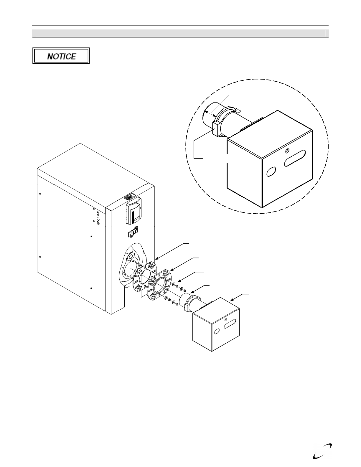
c. Riello Burners (extra step required): Mount the burner gasket and burner flange to the boiler. Secure to
the boiler using washers and nuts provided (Figure 4-5). Seal around the burner gasket and the blast tube
ring with high temperature silicone (i.e. 83ml tube of silicone included in the burner kit).
d. Mount prepared burner package to the boiler. Seal around burner flange with high temperature silicone.
Combustion Air Settings - Refer to Section 10.0 Installation Checklist for instruction
regarding adjusting combustion air settings.
Oil Supply Tank and Oil Piping
The oil supply tank and piping should be installed in accordance with the instructions in this manual; the burner
and pump manufacturer’s instructions; National codes NFPA 31 (USA) or CSA B139 (Canada), and local codes.
General Installation Guidelines:
1. Install the oil supply tank as per tank manufacturer’s instructions.
2. Install oil supply piping from the tank to the burner.
3. Recommend installing a low pressure-drop fuel oil filter to prevent burner nozzles plugging at low flow rates.
4. Shut-off valves should be installed to control the flow during operation and to avoid spills during servicing.
5. Oil can be fed from the supply tank by gravity (single pipe system) or by transfer pump (two-pipe lift system).
6. Refer to burner manufacturer’s instructions before installing oil piping systems as some burner packages are
not equipped to work with two-pipe lift systems (i.e. Riello BF5).
7. Connect oil supply piping to the fuel oil pump as per the pump manufacturer’s instructions and system type.
Pipe Dope / Teflon Tape - DO NOT use on direct oil connection to the fuel pump. Failure
to follow instructions may cause valve failure and dangerous operating conditions.
12
C 85-340 Boiler Assembly - Installation & Operation Instructions
Figure 4-5 Burner Installation
Prepare the burner as per the burner manufacturer’s instructions. Refer to Tables 2-1 to
2-3 for nozzle sizes, burner settings, insertion depths, air settings, and specifications.
Set insertion depth
(Tables 2-1 to 2-3)
Blast Tube Ring
│
Odyssey
Burner Gasket
Burner Flange
Washers and Nuts
Blast Tube
Burner
13

Odyssey
5.0 GENERAL VENTING
│
Installation and Operation Instructions - General Venting CT80-250
Natural Draft Applications
All Odyssey models are certified as Natural Draft boilers. The Natural Draft installation draws combustion air
from the room and uses the stack effect and draft system to exhaust flue gases using a chimney.
Air Supply - Allowances for combustion air must be supplied to the appliance space, due to the fact that the
heating appliance consumes large volumes of combustion air. In most instances, a permanent opening with an
unobstructed or “free area” of 1 square inch for every 1000 BTU’s of input will provide a sufficient amount of
combustion air for the boiler to operate properly. If the building is fairly new and relatively air tight, compensate
for the air tightness by using a “free area” that is 15% larger that what was calculated above. Do not place the
boiler in, or adjacent to, a room where an exhaust fan is operating. Refer to “Combustion Air” in Section 6.0
Natural Draft Applications for more details. Installation must comply with Standard CSA B139 (Canada) and
NFPA 31 (USA).
Stack Draft - Sufficient draft by natural or mechanical means is necessary for ensuring optimal and consistent
operation. The appliance should have a stack draft sufficient to support stable operation. See Draft Settings
(Natural Draft).
Avoiding Condensation - Due to the high combustion efficiencies and low stack gas
temperatures, great care must be taken to ensure that the chimney isn’t subjected to gas
condensation. The exhaust gas temperature where the flue pipe enters the chimney must be a minimum of 240oF
or condensation may occur.
Draft Regulator - A draft regulator must be used and set to regulate the draft of the boiler. Make sure that the
damper is free to operate without sticking, for this will affect the boiler’s combustion system. It is important that
the draft be adequate because poor draft conditions will cause poor operation and a possible hazardous condition.
Draft Settings (Natural Draft) - The Odyssey is designed to operate with a -.03” w.c.
draft in the flue breaching; therefore, ensure there is enough natural or mechanical draft
for proper operation. Due to the design of the Odyssey it may operate at a positive over fire pressure up to +.20 at
a -.03 draft.
Direct Vent Applications
Odyssey models C85-150 are also certified for direct vent applications. The Direct Vent installation uses a special
venting system where exhaust gases are vented directly to the outside using a special venting system which
equalizes the pressure between the air inlet and the flue outlet resulting in a balanced flue system. Refer to Section
7.0 Direct Vent Applications for more details. Installation must comply with Standard CSA B139 (Canada) and
NFPA 31 (USA).
Draft Settings (Direct Vent) - Due to the design of the balanced flue system, the Odyssey
will operate at a positive draft pressure and a positive over fire pressure at all times. It is
designed to operate with a maximum stack draft of 0.25” w.c and a maximum over fire draft of 0.33” w.c. when
little or no wind is present. In extreme wind conditions, the maximum stack draft is 0.35” w.c. and the maximum
over fire draft is 0.45” w.c.
14
 Loading...