


ASSEMBLY INSTRUCTIONS
TM
®

i
O’DONNELL HISTORY
Every dream has a beginning and an end. This one just happened
to start out in the O’Donnell family garage back in 1980. Young
Steve O’Donnell wasn’t satisfi ed with the mediocre products
that the RC industry had to offer, so he set out to build the best
engineered and manufactured products available. Lucky for us, his
dream is far from over…
O’Donnell took his vast knowledge of nitro engine tuning and soon
designed products that would complement his talents. First came
his custom designed and machined aluminum cooling heads for
the on-road racing scene. Finding another void in the industry, he
also began producing custom tuned pipes to better utilize all of the
power these nitro burning monsters could produce.
The efforts of O’Donnell did not go overlooked. Some of the major
R/C manufacturers went to O’Donnell Manufacturing to have their
trick aluminum parts machined. O’Donnell’s meticulous standards
and overwhelming knowledge of the products made it a natural fi t.
Over the past 24 years, O’Donnell Manufacturing has produced parts
for such notable companies as Team Associated and Team Losi.
O’Donnell Manufacturing took another major step forward in 1988
when they introduced O’Donnell Racing Fuel…the name that
made them famous with racers around the world. Once again,
O’Donnell saw a need — for a high-quality fuel specifi cally blended
for the demands of nitro burning car engines. From that point on,
O’Donnell Racing Fuel became synonymous with winning. To this
day, no other fuel has won as many national championships as
O’Donnell Racing Fuel.
Not afraid to take chances on long shots, in 1999 O’Donnell spotted
a little kid from the hills of California who had a great deal of driving
talent. This kid would later become a National Champion in both
electric and nitro. He would also go on to TQ and win the IFMAR
World Championships. That kid was the one and only Jared Tebo.
The name Tebo quickly became associated with O’Donnell and
winning. He’s known around the world for his race-winning talent.
O’Donnell’s dreams moved to the next level when he embarked
on the ultimate journey…the design and creation of a new 1/8
off-road nitro racing buggy. The plan was simple: Don’t try to “reinvent the wheel”, just refi ne it…all of it.
Now, after extensive development, refi nement, testing, and ontrack race-winning results, we are proud to introduce the Ultimate
Racing Machine –
Designed by O’Donnell, Tested by Tebo….the Z01-B.
To complement the racing fuel, O’Donnell set out in 2000 to design
a glow plug that would out-perform and out-last all the competitors.
The result? Two U.S. patents and a World Championship. Not
bad for someone who started out in his parents’ garage. Today,
O’Donnell glow plugs are the choice of champions worldwide.
ii
• O’Donnell® guarantees this kit to be free from defects in both
material and workmanship at the date of purchase. O’Donnell will
warranty this kit for 90 days after the purchase date. O’Donnell
will repair or replace, at no charge, the incorrectly made part.
• Make sure you save the receipt or invoice you were given when you
bought your model! It is your proof of purchase and we must see
it before we can honor the warranty. Further, O’Donnell reserves
the right to change or modify this warranty without notice.
• In that O’Donnell has no control over the fi nal user assembly or
material used for fi nal user assembly, no liability shall be assumed
nor accepted for any damage resulting from the use by the user
of the fi nal user-assembled product. By the act of using the userassembled product, the user accepts all resulting liability.
WARRANTY
To return your Z01B for repairs covered under warranty you should
send your buggy to:
Hobby Services
3002 N. Apollo Drive Suite 1
Champaign, Illinois 61822
Attn: Service Department
Phone: (217) 398-0007 9:00 am-5:00 pm Central Time M-F
E-mail: hobbyservices@hobbico.com
www.hobbyservices.com
If the buyer is not prepared to accept the liability associated
with the use of this product, the buyer is advised to return
this kit immediately in new and unused condition to the place
of purchase.
2

iii
3
SAFETY PRECAUTIONS
Use care and good sense at all times when operating this radio
controlled buggy. Failure to use this vehicle in a safe, sensible
manner can result in injury or damage to property. You and you
alone must insure that the instructions are carefully followed and
all safety precautions are obeyed.
• Do not operate the Z01B near people. Spectators should be
behind the driver or at a safe distance away from the vehicle.
• Water can cause the electronics to short out and can cause
permanent damage.
• Always turn on the transmitter before turning on the receiver.
• Fully extend the transmitter antenna before operating your vehicle.
• Before turning on your radio system, check to make sure that no
one else is running on the same frequency.
• The engine and exhaust produce quite a bit of noise. Do not run
this vehicle when or where it can disturb others.
• The engine and exhaust can become very hot. Avoid touching
any of these parts during use and until they have cooled down.
• Model engine fuel is poisonous. Make sure you read and follow
all of the precautions on the fuel container. Keep fuel out of the
reach of children.
• Model engine fuel is fl ammable and when ignited has a fl ame
that is diffi cult to see. Avoid sparks, fl ames, smoking, or any
other ignition source when fuel is near.
• The engine emits harmful fumes just like real vehicles. Do not
operate this model indoors.
• Avoid running the buggy in cold weather. The plastic and metal parts
can become brittle at low temperatures. In addition, grease and oil
become thick, causing premature wear and poor performance.
iv
• Read the instructions carefully before starting assembly.
• We recommend building the kit on a towel to help prevent small parts and screws from rolling off your work surface.
• Before turning on your radio system, check to make sure that no one else is running on the same frequency.
• Do not use an electric screwdriver/drill for assembling the kit. This could cause parts to strip out from overtightening.
• Use a quality threadlock where specifi ed in the manual.
• Parts for step included in this parts bag.
• Apply grease to part(s) indicated. Note: Always use black moly grease on areas indicated.
• Apply threadlock to screw(s) indicated. IMPORTANT: Clean oil or fi lm from screws before applying threadlock.
G
re
Threadlock
1
a
s
e
GENERAL BUILDING TIPS
3
v
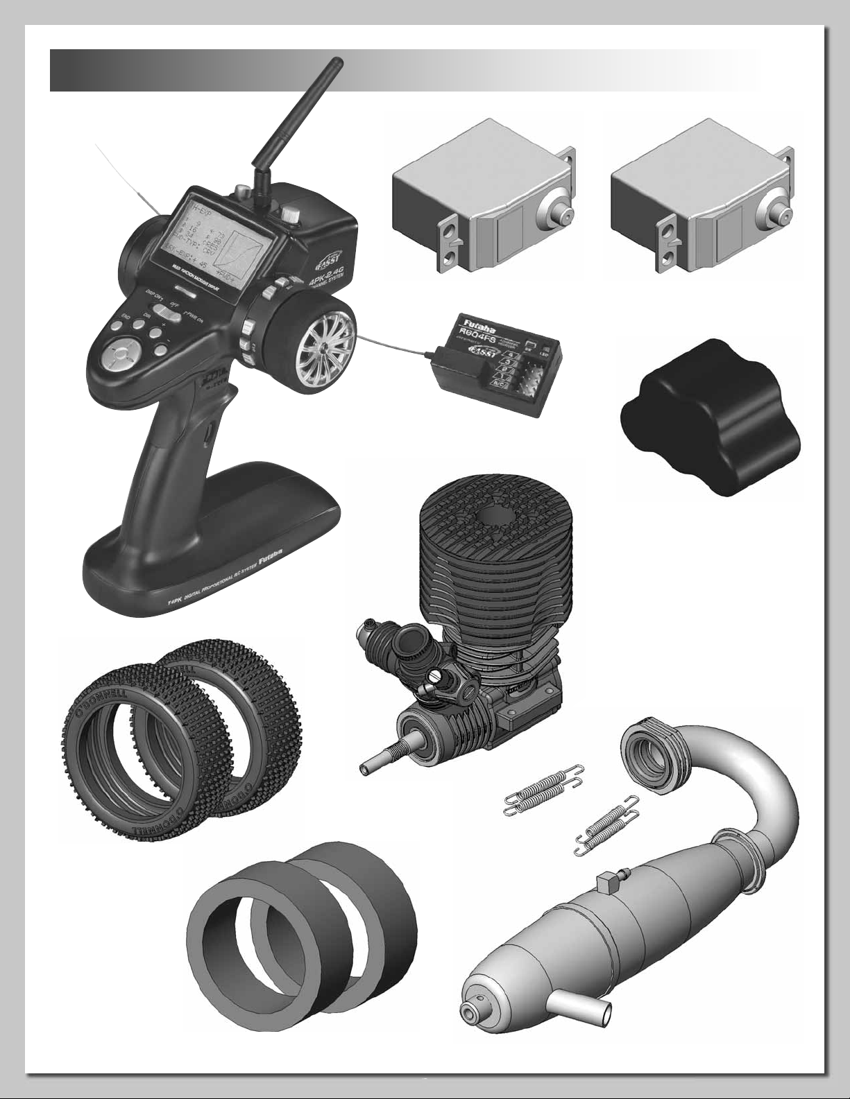
REQUIRED ACCESSORIES
Transmitter
Receiver
High Torque
Steering Servo
Servo
5-Cell Receiver
Hump Pack
Tires
Engine
Header & Pipe
Tire Inserts
4
vi
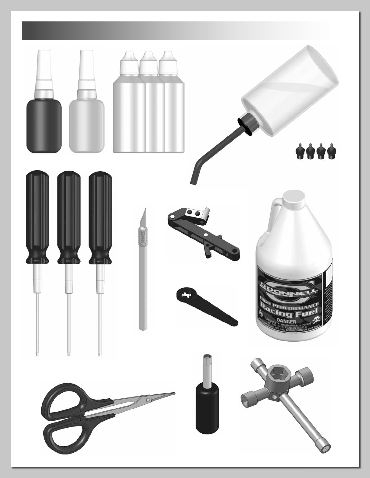
REQUIRED TOOLS & TRACK EQUIPMENT
Threadlock CA Tire Glue
Diff, Shock & Air Filter Oils
Clutch Tool
Fuel
Bottle
Glow Plug
(and spares)
Flywheel
Wrench
1.5mm Hex
Wrench
2.0mm Hex
Wrench
2.5mm Hex
Wrench
Body
Scissors
Hobby
Knife
Fuel
4-Way
Wrench
Glow Plug
Ignitor
5
1
6
Grease
Grease
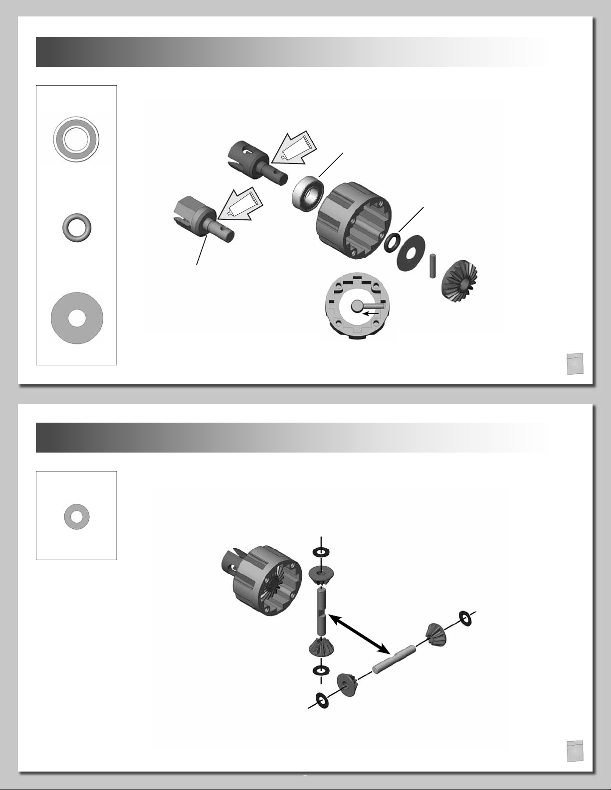
HARDWARE
DIFF HOUSING
(x3)
8x16mm Bearing
(x3)
Diff Outdrive O-Ring
(x3)
Sun Backing Washer
Front/Rear (x2)
Center (x1)
Apply grease in the groove
and a light fi lm of grease
on the shaft of all outdrives.
Make sure the bearing is fully
seated on the diff housing.
Slide the pin in place using
needle-nose pliers.
Apply a small amount of included
grease to the O-ring before installing.
This will help prevent damage to the
O-ring when installing the drive joint.
1
2
HARDWARE
Satellite Backing
Washer
DIFF PLANETARY GEARS
(x12)
Make sure the fl at spots on
the planetary gear shafts
interlock when installing.
1
6
3
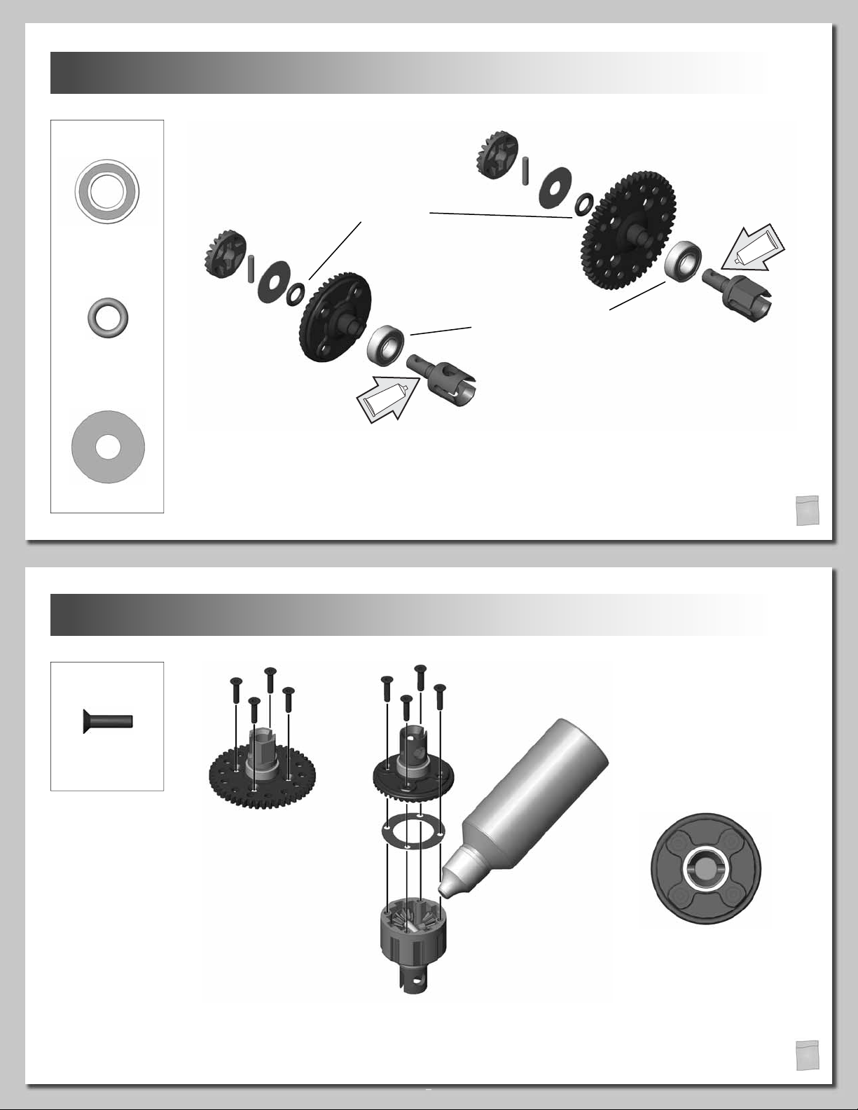
DIFF OIL
Grease
Grease
HARDWARE
(x3)
8x16mm Bearing
(x3)
Diff Outdrive O-Ring
Apply a small amount of the included
grease to the O-ring before installing.
This will help prevent damage to the
O-ring when installing the drive joint.
Make sure the bearing is
fully seated on the gear.
SPUR/DIFF GEARS
Center
(x3)
Sun Backing Washer
4
HARDWARE
(x12)
3x12mm FH
Screw
Apply grease in the groove
and a light fi lm of grease
on the shaft of all outdrives.
Fill the diff until the planetary
gear shafts are completely
covered with diff oil. When
using heavy oils, you need to
allow the oil to settle and add
oil if necessary. Do not overfi ll!
(Note: See set-up sheet for
recommended diff oils.)
Front/Rear x2
Build the front, rear and center diffs.
DIFF OIL
DIFF OIL
1
4
Finish tightening the diff
gear screws in order. This
will help make sure the gear
is mounted fl at on the diff
housing and the housing is
properly sealed.
3
2
1
1
7
5
8
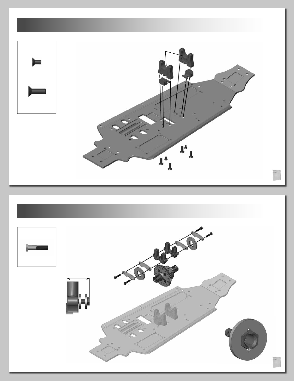
IMPORTANT!
IMPORTANT!
HARDWARE
3x6mm FH
Screw
4x12mm FH
Screw
(x2)
(x4)
IMPORTANT!
The grooves for the diff
bearings face inward.
Make sure the brake disc guides
are interlocked with the diff
mounts before installing.
CENTER DIFF MOUNTS
3x6mm FH
6
HARDWARE
(x4)
Brake Pad Bolt
IMPORTANT!
Brake pad bolt adjustment
must be correct.
16.75mm
4x12mm FH
Small
4x12mm FH
2
MOUNT THE CENTER DIFF
Large
Front
Line up brake disc notch.
2
8
7
IMPORTANT!
T
h
re
a
d
lo
c
k
T
h
r
e
a
d
l
o
c
k
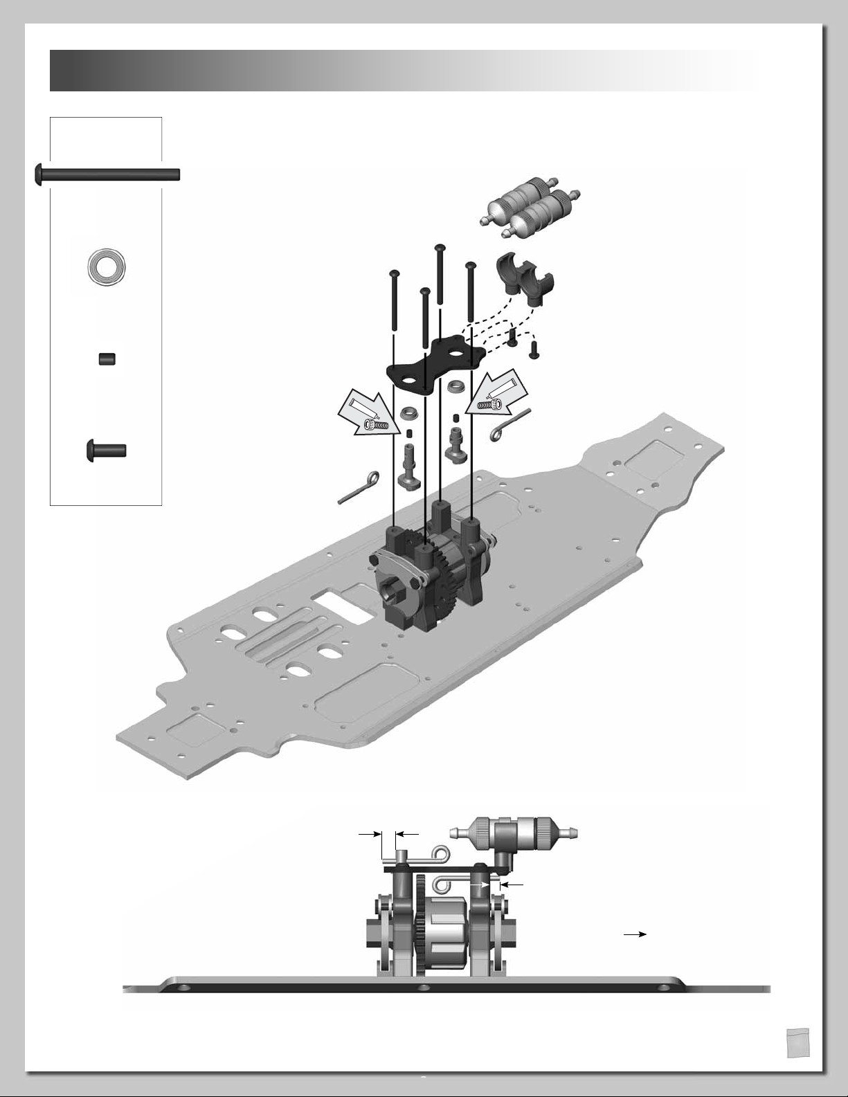
HARDWARE
3x35mm BH
Screw
5x8mm Flanged
Bearing
3x4mm Set
Screw
(x4)
(x2)
(x2)
BRAKE ACTUATOR & FUEL FILTER MOUNT
IMPORTANT!
Mount the fuel fi lter mount to the center
upper brace before installing the center
upper brace to the center diff mounts.
3x8mm BH
Screw
(x2)
Install the brake actuator rods
into the brake actuators and
secure them with 3mm set
screws before installing the
upper plate.
5.5mm
Long
The angled side of the brake
Short
actuator faces the brake plate.
4.25mm
Front
9
2
8
10
IMPORTANT!
T
h
re
a
d
lo
c
k
G
re
as
e
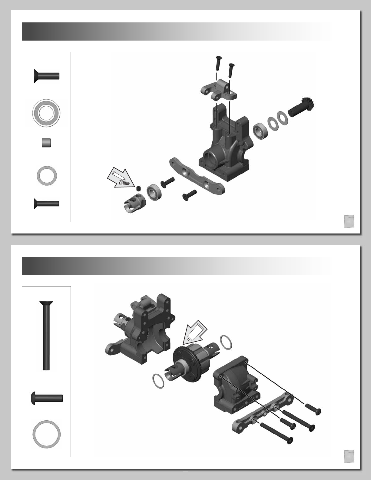
HARDWARE
REAR DIFF JOINT
3x14mm FH
4x14mm FH
Screw
8x16mm Bearing
5x5mm Set
Screw
Pinion Shaft Shim
3x14mm FH
Screw
(x2)
(x2)
(x1)
(x2)
(x2)
Make sure the bearings are
fully seated in the case.
4x14mm FH
3
9
HARDWARE
4x40mm FH
Screw
4x16mm BH Screw
(x2)
(x2)
IMPORTANT!
Apply a 1/4" strip of the included
grease to three locations on the
ring gear.
REAR DIFF HOUSING
Use the included shims to space gears properly
in the diff case. Adjust the gear mesh for smooth
rotation without excessive play. The number of
shims needed, and the side on which they must
be placed, may vary.
(x2)
Diff Shim
10
3
10
T
h
r
e
a
d
lo
c
k
T
h
re
a
d
lo
c
k
T
h
r
e
a
d
lo
c
k
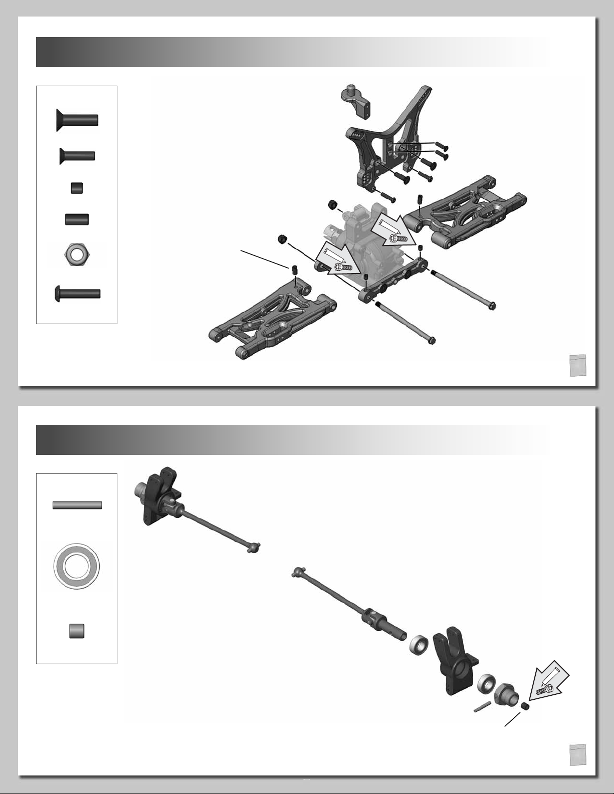
HARDWARE
4x14mm FH Screw
3x12mm FH Screw
4x4mm Set Screw
4x8mm Set Screw
4mm Lock Nut
(x2)
(x2)
(x2)
(x2)
(x2)
Refer to the setup sheets
for droop settings.
REAR SHOCK TOWER
3x12mm FH
4x14mm FH
3x14mm BH
Right
4x4mm SS
3x14mm BH Screw
11
HARDWARE
Wheel Hub Pin
8x16mm Bearing
(x2)
(x2)
(x4)
4x8mm SS
Left
3
REAR OUTDRIVES
Use the shorter universals
for the rear.
(x2)
5x5mm Set Screw
Make sure the bearings are
fully seated in the hub.
Secure the axle pin in the drive
hub using the 5mm set screw.
3
11
 Loading...