

ODM TTK-720, VIS 300C-PM-02-V, DLS 355 User Manual
TTK 720
Wireless Industry Fiber Test Kit
User Guide

Introduction
The TTK 720 test kit is an all-in-one solution for performing ber inspection, insertion (dB) loss
testing, and red laser continuity testing. This kit has been specically designed to meet the needs of
technicians working in the wireless communications eld.
Kit Overview
Item Description
All-in-one test platform for ber scoping, dB loss testing, and red laser continuity testing. Includes
VIS 300C-PM-02-V
DLS 355 Dual laser source - outputs 1310 and 1550nm wavelengths for dB loss testing singlemode ber.
AC 029 LC adapter for OPM port on VIS 300C unit.
touchscreen monitor with customized software and high-denition inspection probe. Power meter and
VFL included.
AC 107B
AC 048B 1.25mm universal inspection adapter for VIS 300C probe.
AC 049B 2.5mm universal inspection adapter for VIS 300C probe.
AC 040B SC bulkhead inspection adapter for VIS 300C probe.
AC 044B LC bulkhead inspection adapter for VIS 300C probe.
AC 4500 Loopback module - single mode. Used to loop signal at tower top in order to test both bers in the pair.
AC 523
AC 602 LC duplex bulkhead. Used to connect AC 523 to trunk bottom.
AC 089 One-click cleaner for all 1.25mm ferrules. Dry-clean method.
AC 092 Fiber cleaning pad and pen for all exposed ferrules. Wet/Dry clean method.
AC 802 USB cable for data transfer to computer.
AC 015 Large hard carry case.
LC 60-degree bulkhead inspection adapter for VIS 300C probe. May be used to scope dicult bulkheads,
such as those in tower-top enclosures.
Loopback test jumper - plugs into DLS 355 and OPM port on VIS 300C unit in order to plug onto the
ber trunk pair at the tower bottom.
M-UM010-02 TTK 720 06/18
Page 2
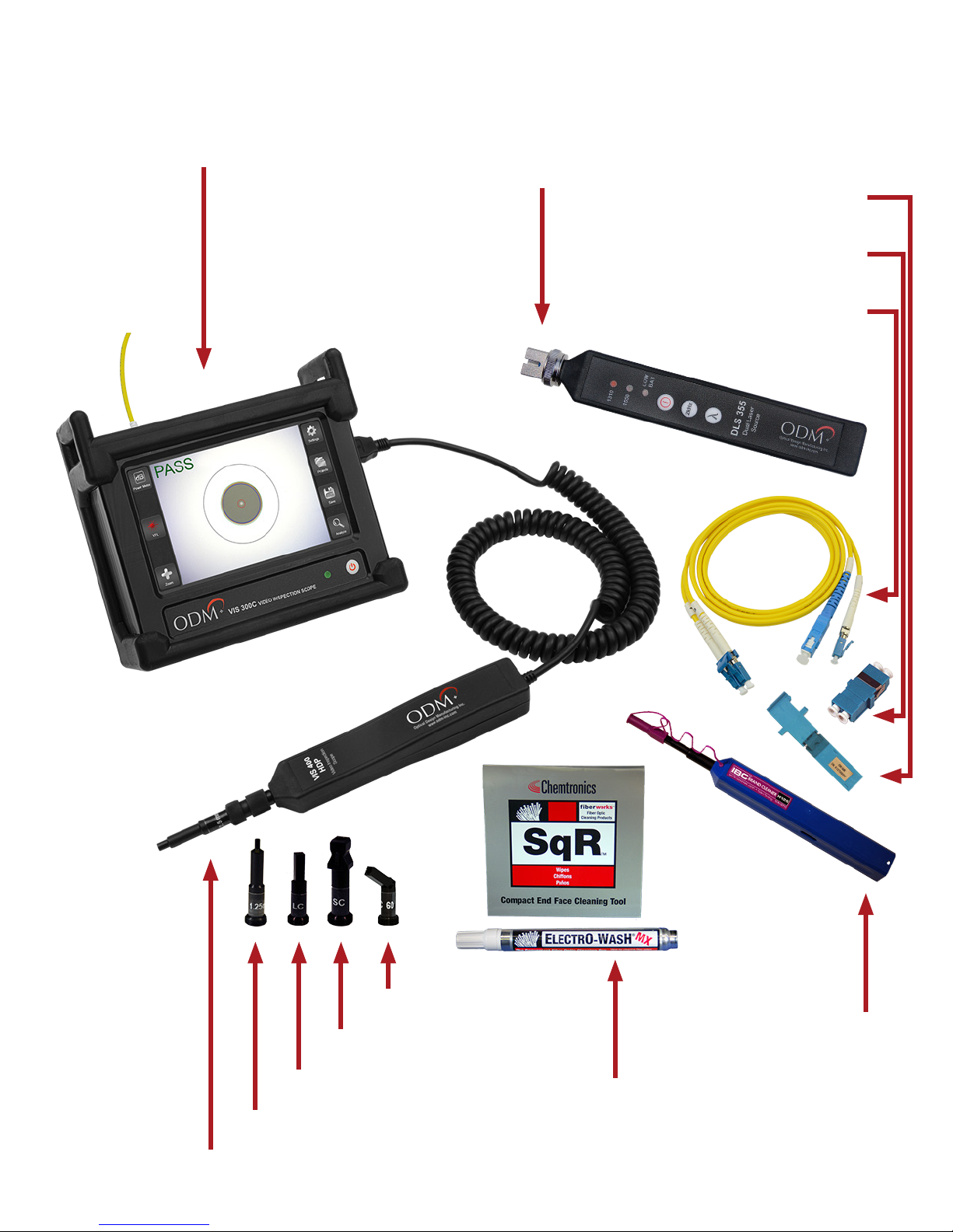
Kit Overview
VIS 300C-PM-02-V*
*VFL , OPM, and Scope included
DLS 355
AC 4500
AC 602
AC 523
AC 044B
AC 048B
AC 049B
AC 107B
AC 040B
AC 092
M-UM010-02 TTK 720 06/18
AC 089
Page 3

Test Procedures Overview
The following section will provide an overview of the workow and recommended procedures for
each test that can be performed with the TTK 720 kit. Some procedures may have more importance
placed on them by the carrier: please use these procedures only as a guideline. Wireless carrier
requirements supersede ODM’s recommended procedures in all circumstances.
1
Proper Equipment Care Between Uses
This section explains how to properly maintain the TTK 720 test kit components between uses.
VIS 300C charging, equipment cleaning, and storage are discussed.
Creating a New Folder in VIS 300C Software
2
When arriving at a new test site or when starting a new project, the user should create a new “Project
Folder” on the VIS 300C unit. This stores all relevant site information (scope images, loss readings, etc.
in one place. This section covers setting up for a new test site.
Fiber Scoping
3
Fiber inspection should be performed before making any connections onsite. Analysis and saving of
images may be required for closeout packages. This section explains how to inspect and clean ber.
dB Loss Testing
4
Also known as “insertion loss” or “ber sweep” testing, dB loss testing allows the technician to validate
that all ber pairs are in working condition. Saving of dB loss test results may be required for closeout
packages. This section explains the necessary steps for testing ber.
VFL Testing
5
An onboard red laser allows users to verify proper continuity of ber cables. This is a troubleshooting
task only. This section gives an overview of the VFL functionality.
Creating and Sharing Reports
6
The VIS 300C has built-in report creation software. This section explains how to create reports for
closeout packages.
M-UM010-02 TTK 720 06/18
Page 4
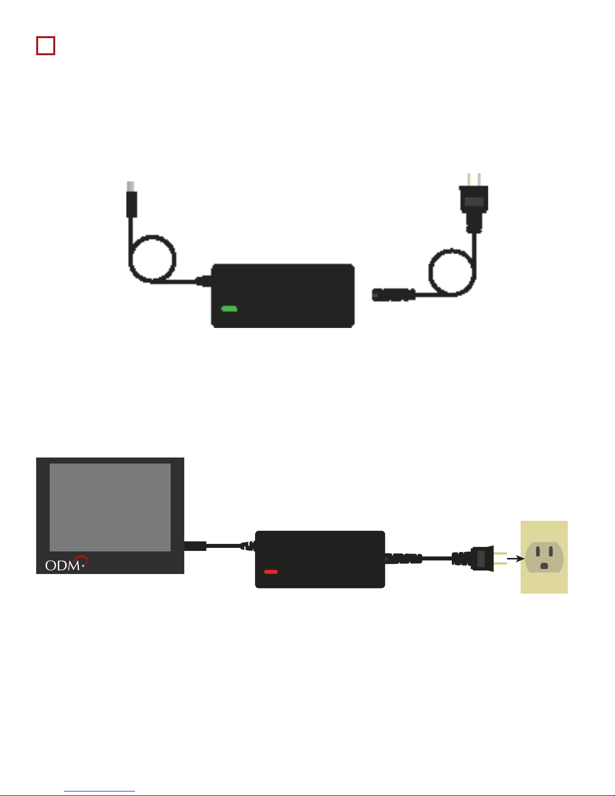
1
Wall Plug
Green when fully charged
Proper Equipment Care Between Uses
1a - Charging the VIS 300C
The VIS 300C charger comes in two pieces. See diagram below. The cable on the right will be
plugged into the power brick to create the charging device.
Allow the VIS 300C to charge fully between uses. The VIS 300C can be used while charging;
please be aware that an internal fan may activate to regulate temperature. 4-5 hours battery
life typical for a single charge.
VIS 300C
Light on Charger:
Red when charging
M-UM010-02 TTK 720 06/18
Page 5
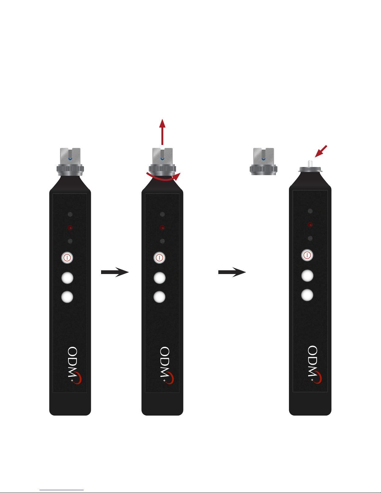
1b - Cleaning the DLS 355
The DLS 355 laser source is a high-end test laser, capable of outputting 1310 and 1550nm
wavelengths. The output port of this unit utilizes a physical connection, which means that it
can become soiled if used improperly. When needed, the DLS 355 adapter may be removed for
inspection and cleaning of the ber ferrule.
DLS 355 is stored with
adapter ON to protect
ferrule inside.
1310
1550
LOW
BAT
2kHz
1310
1550
Remove adapter by
unscrewing until it spins
freely, then pull o.
LOW
BAT
2kHz
Inspect ferrule with
VIS 300C and clean
with appropriate tools.
Always replace adapter.
1310
1550
LOW
BAT
2kHz
λ
DLS 355
Dual Laser
Source
Optical Design Manufacturing Inc.
www.odm-inc.com
λ
DLS 355
Dual Laser
Source
Optical Design Manufacturing Inc.
www.odm-inc.com
λ
DLS 355
Dual Laser
Source
Optical Design Manufacturing Inc.
www.odm-inc.com
Regular inspection and cleaning of the output port of the DLS 355 may not be necessary if
appropriate procedures are followed. Always inspect test jumpers before they are plugged into
the DLS 355 and store it properly to ensure continued performance.
M-UM010-02 TTK 720 06/18
Page 6
1c - Inspecting and Cleaning Fiber Jumpers and Loopback
Special care should be taken to ensure the continued function of all test jumpers and
loopbacks. A regular inspection and cleaning regimen will keep kit components functional for a
longer period of time.
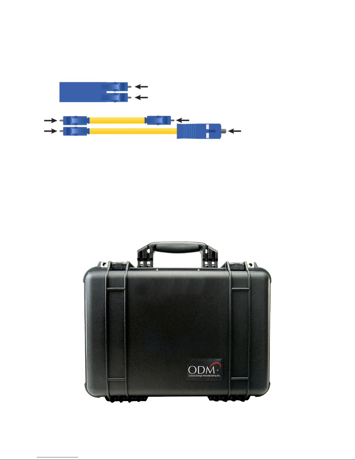
AC 4500
1d - Equipment Storage
All equipment should be stored in the airtight case provided by ODM. Keep the case in a cool,
dry location and remove battery from the DLS 355 if it must be stored for over 6 weeks.
Each arrow in the diagram at left
indicates a ber ferrule that should be
inspected and cleaned between uses.
AC 523
M-UM010-02 TTK 720 06/18
Page 7

Creating a New Folder in VIS 300C Software
2
The VIS 300C platform saves all test information in a folder system onboard. The internal memory is
capable of saving thousands of images and power meter readings. Follow the steps below to create a
new folder when beginning a project.
2a - Create a New Project
Touch
“Projects” Button
Main Inspection
Screen
Touch
“New Project”
Give the project a name using the onscreen keyboard. Touch “Create” to make the project folder.
Enter Project
Name
Touch
“Create”
M-UM010-02 TTK 720 06/18
Page 8

The next screen contains several text elds which help make the project unique. Fill out these elds
using the onscreen keyboard as appropriate, then touch “OK”. You’ll be taken back to the Main
Inspection Screen.
Enter all
Project Details
Touch
“OK”
2b - Change Project Information
If you ever need to change this information, touch “Projects” on the main screen of the unit,
then touch “View Projects,” then choose the appropriate project name. The screen shown below
will appear. Touch the settings icon in the top right of the window to make changes to this
information.
Touch
Settings Icon
M-UM010-02 TTK 720 06/18
Page 9
 Loading...