

ODB SKB700 Owner's Manual

SKB700
SKB700
Self Contained Leaf Collector
Self Contained Leaf Collector
Pre-Operating Manual
Operating Manual
Maintenance Manual
ODB Company
5118 Glen Alden Drive
Richmond, VA 23231
800-446-9823
www.leafcollector.com
Owner's Manual
Safety Manual
Service Manual
Parts Catalog
2018 DIESEL Edition
SKB700
819210

DO NOT ATTEMPT TO OPERATE
OR REPAIR
THE LEAF COLLECTOR WITHOUT FIRST
READING AND UNDERSTANDING THIS
MANUAL
IF YOU HAVE ANY QUESTIONS CONCERNING THE
INSTALLATION OR OPERATION OF THIS UNIT, PLEASE CALL
ODB FOR ASSISTANCE BEFORE ATTEMPTING TO REPAIR OR
OPERATE THE UNIT.
IMPROPER USE OF ANY MACHINE CAN
RESULT IN SERIOUS INJURY!
STUDY AND FOLLOW ALL SAFETY
PRECAUTIONS BEFORE OPERATING OR
REPAIRING UNIT
THIS MANUAL IS AN INTEGRAL PART OF THE LEAF COLLECTOR AND SHOULD
BE KEPT WITH THE UNIT WHEN IT IS SOLD.
ODB COMPANY
5118 Glen Alden Drive
Richmond, VA 23231
800-446-9823

SAFETY PRECAUTIONS
Read and understand this entire manual before operating, maintaining or repairing the leaf vacuum.
If the decal above is missing or damaged call ODB immediately and we will send you a replacement free of
charge. Never operate a unit with damaged or missing safety decals.
DO NOT RIDE, SIT OR STAND ON UNIT
DO NOT MODIFY THE UNIT FOR RIDERS IN ANY
WAY. SERIOUS INJURY OR DEATH MAY OCCUR
ODB’s leaf collectors are NEVER to be used to accomodate riders. If your unit has been modied
to accomdate riders, remove these modications immediately as this can result in serious injury or
death.
ODB COMPANY
800-446-9823 SKB700
3

Municipal Products
Municipal Products
Since 1910
ODB COMPANY
5118 Glen Alden Drive
Richmond, VA 23231
800-446-9823
www.odbco.com or
www.leafcollector.com
Since 1910
THANK YOU
Thank you and Congratulations on your puchase of your ODB Leaf Collector. Your ODB leaf collector has been carefully designed and manufactured to give you a maximum amount of dependability and years of trouble-free operation. Take comfort in the fact the ODB has been manufacturing
municipal products since 1910 and takes pride in our product's quality and our customer service.
Please take the time to thoroughly read this manual, as well as the engine manual, in its entirety before operating, maintaining, servicing or repairing your leaf collector. Please thoroughly review and
follow all the safety procedures located in this manual.
Whenever you need replacement parts, service information or any question regarding your ODB
product please feel free to contact us at 800-446-9823 or www.odbco.com.
Please record the following information for future reference:
Model No.:
Serial No.:
Vin No:
Engine Serial No.:
Date of Purchase:
ODB COMPANY
800-446-9823 SKB700
4

TABLE OF CONTENTS
Read and understand this entire manual before operating, maintaining or repairing the leaf vacuum.
Table of Contents
Contents
SKB700 .......................................................................................................................................................... 1
Table of Contents ...........................................................................................................................................5
1.0 GENERAL SAFETY
1.1 Safety Symbol Denitions ....................................................................................................................10
1.2 Do’s and Do Not’s:.................................................................................................................................11
1.3 Training: .................................................................................................................................................13
1.4 Safety Decals ......................................................................................................................................15
2.0 PRE-OPERATING SECTION
2.1 Instruments and Controls: ..................................................................................................................... 17
2.2 Safe Operations: ..................................................................................................................................... 19
2.3 Preparation For Operation ......................................................................................................................21
2.4 Pre-Transport Checks .............................................................................................................................22
2.5 Personal Protective Equipment and Clothing ........................................................................................24
2.6 Work Site Preparation ............................................................................................................................25
3.0 OPERATING SECTION
3.1 Starting Engine .......................................................................................................................................27
3.2 Engaging the PTO .................................................................................................................................. 29
3.3 Fluid Drive Coupler (if equipped) .........................................................................................................31
3.4 Vacuuming Leaves .................................................................................................................................32
4.0 MAINTENANCE SECTION
4.1 Maintence Overview: ............................................................................................................................. 34
4.2 Maintenance and Lubrication ...............................................................................................................35
4.3 Lubrication: ............................................................................................................................................ 36
4.4 Preventative Maintenance ...................................................................................................................... 38
4.5 Torque Values ........................................................................................................................................ 43
4.6 Torque Values ........................................................................................................................................ 44
5.0 SERVICE SECTION
5.1 Engine Electrical Troubleshooting Guide .............................................................................................. 48
5.2 Auto Mfg. Clutch Adjustment - 2008 and after .....................................................................................49
5.3 Hydraulic Boom Troubleshooting Guide ...............................................................................................50
5.4 Impeller Installation and Removal ......................................................................................................... 51
5.4 Impeller Installation and Removal, continued ....................................................................................... 52
5.5 Replacing the Drive Belt (if equipped) .................................................................................................. 53
5.5 Replacing the Drive Belt (if equipped) .................................................................................................. 54
5.6 Flange Bearing Installation and Removal (if equipped) ........................................................................ 55
5.6 Flange Bearing Installation and Removal, cont. .................................................................................... 56
5.6 Flange Bearing Installation and Removal, cont. .................................................................................... 57
5.7 Replacing the Blower Housing Liners ................................................................................................... 58
5.7 Replacing the Blower Housing Liners; continued, ................................................................................ 59
ODB COMPANY
800-446-9823 SKB700
5

TABLE OF CONTENTS
Read and understand this entire manual before operating, maintaining or repairing the leaf vacuum.
5.8 IQAN ADVANCED SCREENS
5.8.1 Adjust Menu ............................................................................................................................................. 61
5.8.1 Adjust Menu ............................................................................................................................................. 62
5.8.2 Measure Menu ......................................................................................................................................... 63
5.8.2 Measure Menu ......................................................................................................................................... 64
5.8.3 Preferences Menu ..................................................................................................................................... 65
5.8.4 Info Menu ................................................................................................................................................. 66
5.8.4 Info Menu, continued ............................................................................................................................... 67
5.8.5 IQAN Error Codes ................................................................................................................................... 68
5.8.5 IQAN Error Codes, continued ................................................................................................................. 69
5.8.5 IQAN Error Codes, continued ................................................................................................................. 70
5.8.5 IQAN Error Codes, continued ................................................................................................................. 71
5.10 WIRING DIAGRAMS
5.10.1 Engine Wiring Diagram ......................................................................................................................... 73
5.10.2 Engine Main Harness - Enlarged ........................................................................................................... 74
5.10.3 Auxillary Engine Harness - Enlarged..................................................................................................... 75
5.10.4 Engine Wiring Harness Descriptions ..................................................................................................... 76
5.10.4 Engine Wiring Harness Descriptions, continued ................................................................................... 77
5.10.5 Engine Rocker Switch Wiring Diagrams ............................................................................................... 78
5.10.6 Main Circuit Board ................................................................................................................................ 79
5.10.7 Main Circuit Board Plug Diagrams ....................................................................................................... 80
5.10.14 Boom Wiring Diagram ......................................................................................................................... 81
5.10.15 Remote Throttle / Clutch Wiring Harness ........................................................................................... 82
5.11.1 Wiring Harness Overview Diagram ....................................................................................................... 83
5.11.2 Engine Wiring Harness Diagram ........................................................................................................... 84
5.11.3 Valve Body Wiring Harness Diagram .................................................................................................... 85
5.11.4 XA2 and XS2 Module Wiring Harness Diagram ................................................................................... 86
5.11.5 Engine Side Rail Wiring Harness Diagram ............................................................................................ 87
5.11.6 IQAN MD3 Display Wiring Harness Diagram ...................................................................................... 88
5.11.7 IQAN E-Stop,Relay,Joystick & Door Lock Diagrams .......................................................................... 89
5.11.8 IQAN Power Switch and E-Stop Wiring Diagrams ............................................................................... 90
6.0 ENGINE GROUP
6-0 ..................................................................................................................................................................... 92
6.1 Instrument Panel Group ............................................................................................................................. 93
6.2 Air Cleaner Group ....................................................................................................................................... 94
6.3 Sheet Metal Group, SCL ............................................................................................................................. 95
6.4 Engine Mount Group .................................................................................................................................. 96
6.5 Mufer (Exhaust) Assembly ....................................................................................................................... 97
6.6 Radiator Assembly Group ........................................................................................................................... 98
6.7 Engine Senders / Switch Group ................................................................................................................. 99
6.8 Battery Group ............................................................................................................................................ 100
ODB COMPANY
800-446-9823 SKB700
6

TABLE OF CONTENTS
Read and understand this entire manual before operating, maintaining or repairing the leaf vacuum.
6.9 Engine Miscellaneous Parts Group ............................................................................................................. 101
6.10 John Deere Common Engine Parts Group ................................................................................................ 102
6.11 Remote Clutch / Throttle Circuit Board Assembly ................................................................................... 103
6.12 Remote Clutch and Remote Throttle Assembly ........................................................................................ 104
6.13 Chaffe Eliminator Assembly, hinged ........................................................................................................105
7.0 CLUTCH GROUP
7-0 ..................................................................................................................................................................... 106
7.1 AutoHD PTO Clutch Group ........................................................................................................................ 107
7.2 AutoHD PTO Assembly Group ..................................................................................................................108
7.3 AutoHD PTO Linkage Group ..................................................................................................................... 109
7.4 Clutch Assist Group .................................................................................................................................... 110
7.5 Kraft Fluid Drive Group (Optional) ............................................................................................................ 111
7.6 Kraft Fluid Drive Installation (Optional) .................................................................................................... 112
7.7 Kraft Fluid Drive Breakdown (Optional) ................................................................................................... 113
7.8 Kraft Fluid Drive Common Parts (Optional) .............................................................................................. 114
8.0 BLOWER HOUSING GROUP
8-0 ..................................................................................................................................................................... 115
8.1 - 0 Degree Blower and Impeller Group ...................................................................................................... 116
8.2 - 0 Degree Blower Housing Face Group .................................................................................................... 117
8.3 SKB700 90 DEGREE Blower Housing Group .......................................................................................... 118
8.4 SKB700 90 Degree Blower Housing Face Group ...................................................................................... 119
8.5 Belt Drive Pedestal Group .......................................................................................................................... 120
8.6 90 DEGREE Exhaust Ducts Group ........................................................................................................... 121
8.7 Fuel Tank Group ......................................................................................................................................... 122
9.0 BOOM GROUP
9-0 ..................................................................................................................................................................... 123
9.1 Boom Group................................................................................................................................................ 124
9.2 Intake Hose Group ...................................................................................................................................... 125
9.3 M3219 Hydraulic Boom Pump ................................................................................................................... 126
9.4 Valve Body Group ....................................................................................................................................... 127
9.5 Valve Body Mounting Group ...................................................................................................................... 128
9.6 Hinged Boom Frame Assembly - 3 Axis ....................................................................................................129
INDEX
Index ................................................................................................................................................................. 131
ODB COMPANY
800-446-9823 SKB700
7

SAFETY PRECAUTIONS
Read and understand this entire manual before operating, maintaining or repairing the leaf vacuum.
1.0 GENERAL SAFETY
Contents
SKB700 .................................................................................................................1
Table of Contents ..................................................................................................5
1.0 GENERAL SAFETY
1.1 Safety Symbol Denitions ...........................................................................10
1.2 Do’s and Do Not’s:........................................................................................11
1.3 Training: ........................................................................................................13
1.4 Safety Decals .............................................................................................15
1.0
GENERAL
SAFETY
ODB COMPANY
800-446-9823 SKB700
8

SAFETY PRECAUTIONS
Read and understand this entire manual before operating, maintaining or repairing the leaf vacuum.
If the decal above is missing or damaged call ODB immediately and we will send you a replacement free of
charge. Never operate a unit with damaged or missing safety decals.
DO NOT RIDE, SIT OR STAND ON UNIT
DO NOT MODIFY THE UNIT FOR RIDERS IN ANY
WAY. SERIOUS INJURY OR DEATH MAY OCCUR
ODB’s leaf collectors are NEVER to be used to accomodate riders. If your unit has been modied
to accomdate riders, remove these modications immediately as this can result in serious injury or
death.
ODB COMPANY
800-446-9823 SKB700
9

SAFETY PRECAUTIONS
Read and understand this entire manual before operating, maintaining or repairing the leaf vacuum.
1.1 Safety Symbol Denitions
This manual provides the owners/operator with procedures for safe operation, maintenance and repair of your leaf collector. As with any machine,
there are hazards associated with their operation. For this reason safety is
emphasized throughout this manual. To highlight specic safety information the following safety denitions are provided to assist the reader.
The purpose of safety symbols are to attract your attention to possible
dangers. The safety symbols, and their explanations, deserve your careful
attention and understanding. The safety warnings do not by themselves
eliminate any danger. The instructions or warnings they give are not substitutues for proper accident prevention measures.
SYMBOL
!
MEANING
SAFETY ALERT SYMBOL:
tention is required in order to avoid serious personal injury. May be used in
conjuction with other symbols or pictographs.
Disregarding this safety warning WILL result in serious equipment
damage, injury or possible death.
Disregarding this safety warning CAN result in serious equipment
damage, injury or possible death.
Disregarding this safety warning MAY result in minor or moderate
injury or property damage.
Indicates danger, warning or caution. At-
ODB COMPANY
800-446-9823 SKB700
10

SAFETY PRECAUTIONS
Read and understand this entire manual before operating, maintaining or repairing the leaf vacuum.
1.2 Do’s and Do Not’s:
This section contains some general safety precautions to do and not to do.
This is not an all inclusive list and and it is the responsibilty of the operator
to have proper training and use common sense in work situations.
DO NOT:
1. DO NOT operate, maintain or repair this unit without having fully
read and understood ALL the aspects of this manual.
2. DO NOT ride, sit or stand on unit at anytime.
3. DO NOT modify the leaf vacuum for any reasons to allow for riders.
4. DO NOT operate the unit in a state of disrepair.
5. DO NOT operate the unit with ANY guards or safety devices broken,
missing, or inoperable.
6. DO NOT operate the unit without wearing proper safety equipment.
7. DO NOT operate this unit while under the inuence of any alcohol or
medication.
8. DO NOT operate this unit if you have a record of mental instability
or dizziness which could result in injury to yourself or others.
9. DO NOT operate this unit if you are under 18 years of age.
10. DO NOT operate this unit without fully inspecting the unit for any
damage or leakage.
11. DO NOT operate if the unit has any excessive vibration.
12. DO NOT operate unit with the inspection door limit switch damaged
or missing.
13. DO NOT operate unit unless it is properly attached to the tow vehicle.
14. DO NOT tow unit without using all the safety chains.
15. DO NOT tow unit with a damaged tongue.
16. DO NOT ll fuel tank with engine running. Allow engine to cool for 5
minutes before refueling.
17. DO NOT operate unit if fuel is spilled or with fuel cap off.
18. DO NOT smoke or weld near the unit.
19. DO NOT run engine in an enclosed area.
20. DO NOT place hands or feet near moving or rotating parts.
ODB COMPANY
800-446-9823 SKB700
11

SAFETY PRECAUTIONS
Do Not, continued;
21. DO NOT operate engine with an accumulation of grass, leaves or
other debris on the engine.
22. DO NOT run engine with air cleaner removed.
23. DO NOT leave leaf machine unattended while in operation.
24. DO NOT park machine on steep grade or slope.
25. DO NOT vacuum a leaf pile without looking for foreign objects
such as metal, glass, plastic or large pieces of wood.
Do’s:
1. DO completely read and understand the owner’s manual before operating, maintaining or repairing the leaf collector.
2. DO follow engine and PTO manufacturer operating and maintenance instructions.
3. DO check fuel lines and ttings frequently for cracks or leaks.
Replace if necessary.
4. DO completely inspect the unit before leaving the service garage.
5. DO check the tow tongue each day for cracks.
6. DO inspect and be attentive to what is being vacuumed.
7. DO check the impeller, liners and blower housing for cracks or
holes daily.
8. DO wear proper safety equipment as described in this manual.
9. DO watch for pedestrians, animals and other foreign material
when vacuuming leaves.
10. DO replace any worn or missing safety stickers immediately.
ODB COMPANY
Battery posts, terminals and related accessories contain lead and leaf compounds, chemicals know to the state of California to cause cancer and birth
defects or other reproductive harm. Wash Hands after handling
Engine Exhaust, some its constituents and certain vehicle components contain
or emit chemicals known to the state of California to cause cancer and birth defects or other reproductive harm.
800-446-9823 SKB700
12
SAFETY PRECAUTIONS
1.3 Training:
Improper use of the ODB leaf collector CAN result in severe personal injury or death. All personnel using this leaf vacuum must
be trained and qualied with all the operations, maintenance, repair
and safety procedures dened in this manual.
The warnings and procedures regarding safety in this manual are to be
used as a guideline only. It is impossible to cover all the events that could
happen in the vacuuming process. For this reason, it is vital that the
owner accept the responsibility to implement a training program that will
provide every operator or mechanic the basic skills and knowledge to make
good judgement in all situations.
This training program must include the entire scope of hazards, precautions and government regulations encountered in the vacuuming process.
The program should stress the need for regularly scheduled preventive
maintenance and detailed equipment safety checks.
It is strongly recommended that all training programs be documented to
ensure all operators and mechanics receive initial training on not just the
operation but the safety features of the leaf collector.
ODB COMPANY
800-446-9823 SKB700
13
SAFETY PRECAUTIONS
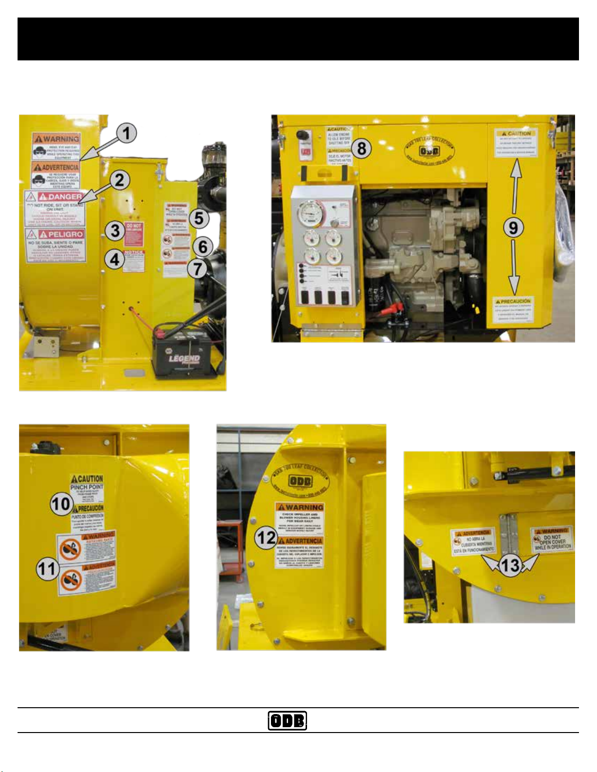
1.4 Safety Decals - Decal Layout for SKB700
ODB COMPANY
800-446-9823 SKB700
14

SAFETY PRECAUTIONS
1.4 Safety Decals
*Read and Follow all Safety
Sticker Warnings--Replace all damaged or missing stickers immediately.
ITEM# PART # DESCRIPTION
1. 200181 Warning--Head, Eye and Ear
2.
3.
4.
5.
6.
7.
8.
9.
10.
11.
12.
13.
200179 Danger- Do Not Ride ...
200109 Do Not Over Lubricate
N/A Prevent Clutch Failure
200182 Do Not Open Cover ...
200183 Danger - Rotating Parts
200191 Warning - Running the Engi..
200193 Caution - Allow Engine to ...
200192 Caution - Do Not attempt ...
200106 Caution - Pinch Point
200183 Danger - Rotating Parts
200189 Warning - Check Impeller ...
200182 Do Not Open Cover ...
ODB COMPANY
800-446-9823 SKB700
15

2.0 PRE-OPERATING SECTION
Read and understand this entire manual before operating, maintaining or repairing the leaf vacuum.
2.0 PRE-OPERATING SECTION
Pre-Operating
2.0
Section
2.0 PRE-OPERATING SECTION
2.1 Instruments and Controls: ................................................................................... 17
2.2 Safe Operations: ................................................................................................... 19
2.3 Preparation For Operation ....................................................................................21
2.4 Pre-Transport Checks ...........................................................................................22
2.5 Personal Protective Equipment and Clothing ......................................................24
2.6 Work Site Preparation ..........................................................................................25
ODB COMPANY
800-446-9823 SKB700
16
Pre-Operating Section
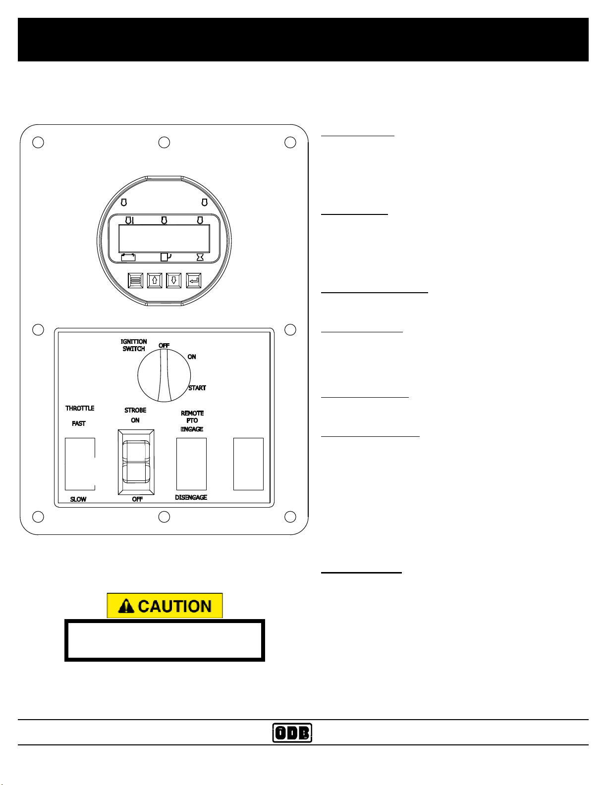
2.1 Instrument and Controls:
Ignition Switch:
Used to power the accessories and start the unit.
ACCESSORIES - rst position
STARTER ENGAGE - second position (springs return
to rst position)
Strobe Toggle
This switch toggles the strobe light on the Blower
Housing (6.3 & 8.2)
CONTROL MODULE
To enter Menu system
Hold Menu button and press Enter◄ button
Always make sure the PTO is
disengaged before starting unit.
Menu Navigation
Press Menu to scroll menu options
Press Up▲ arrow to enter Menu option
Press Down▼ arrow to retun
Exit Menu System
Hold Menu button and press Enter◄ button
To Change A Setting
Press Enter◄ button to bring up brackets [ ]
Press Up▲ arrow button and Down▼ arrow button to
change setting
Press Enter◄ button to make selection, brackets
dissapear
*Recycle Key to the OFF position after changing a
setting*
Main Menus
>Active Engine Fault Codes
View/Scroll Active Codes
>Stored Engine Fault Codes
View/Scroll Stored Fault Codes
ODB COMPANY
800-446-9823 SKB700
17

Pre-Operating Section
2.1 Instrument and Controls, cont.:
>Engine Parameters
View ECU Engine Information
(%Load, Torque, Oil Temp, ect)
>Engine Identication
Engine Model # View
Engine Seriel # View
>Module Information
Control Unit Part# View
Control Unit Software Version View
>Controller Set
Input Conguration
Throttle Conguration
Module Conguration
CAN Conguration
MOD bus Conguration
Source Adsress (Default=44) Others Available
TSC1 Address (Default=3) Others Available
Engine Address (Default=0) Others Available
Oil / Fuel Transmit
>MOD bus Conguration
Baud Rate
Parity
Stop Bits
Slave Address
Enable Gauges
Tachometer Range
Engine Oil Tempertature Range
Transmission Oil Temperature Range
To access the controller setup menus (Conguration Menus), a password is required
Conguration Menus (Controller
Set)
>Input Conguration
Analog 1 Funtion
Digital 1 Function
>CAN Conguration (Throttle)
Throttle type Selection
TSC Minimim Speed
TSC Maximum Speed
TSC Ramp Rate
Throttle Curve Selection
>Module Conguration
Display Units (English, Metric)
Hourmeter Source (Engine ECU, Inter-
nal)
Battery Source (J1939, Internal)
Battery Volt Trim
>CAN bus Conguration
ODB COMPANY
800-446-9823 SKB700
18

Pre-Operating Section
2.2 Safe Operations:
ALL personnel using, maintaining or servicing this unit must be
trained in all safety procedures outlined in this manual. Improper
or careless use of this equipment CAN result in personal injury or
death.
Operations shall be restricted to:
1. Properly trained, qualied and experienced operators and/or qualied and
experienced maintenance and test personnel.
2. Trainees under the direct supervision of qualied and experience
personnel.
3. Qualied and experienced maintenance and service personnel.
Operators who qualify to operate this equipment under the above restrictions shall also comply with the following physical requirements:
1. Have good vision and the ability to read and understand this manual as well
as all safety and operational decals on the equipment.
2. Be capable of hearing, with or without a hearing aid, at a level needed to
safely operate this equipment.
3. A record of mental stability with no history of epileptic seizures, dizziness, or
any other disability that may result in injury to himself or others.
If any of these requirements are not satised at any time, the person failing to
meet these requirements MUST NOT OPERATE THIS EQUIPMENT.
ODB COMPANY
800-446-9823 SKB700
19

Pre-Operating Section
2.2 Safe Operations (continued):
Additional Requirements:
1. Each operator must demonstrate competence to understand all safety decals, operator’s manuals, safety codes, applicable government regulations,
and all other information applicable to the safe and proper operation of the
leaf vacuum.
2. Each operator must demonstrate the ability to recognize an emergency situation that may arise during vacuuming operations and the knowledge and
procedures to implement corrective action.
3. Each operator must demonstrate or provide evidence of qualicatation and
experience prior to operating the leaf vacuum.
4. Each operator must be able to recognize existing or potential problems
regarding the mechanical integrity of the leaf vacuum and report any maintenance requirements to the supervisor in charge.
5. Each operator must wear the proper personal clothing and safety gear. (Re-
fer to SAFETY PRECAUTIONS Section 5.4)
6. Operators must not be physically or mentally fatigued.
7. Operators must not be under the direct or indirect inuence of alcohol and/or
drugs. This includes prescription drugs that could cause drowsiness, dizziness, or any other condition that would impair their ability to operate or use
this equipment in a safe manner.
ODB COMPANY
800-446-9823 SKB700
20
Pre-Operating Section
2.3 Preparation For Operation
Before your leaf vacuum is put into operation it is very important
to read and follow the procedures outlined in the engine owner’s
manual. (EOM).
For specic information regarding the following checks please refer to the
“Maintenance” section of this manual and the engine owner’s manual.
DISENGAGE the clutch and remove the negative battery cable before performing the following checks.
NEVER place any part of the body under or behind guards or any
other area in which you cannot see.
IMPORTANT CHECKS:
NOTE: The following checks contained in the next three sections should be
performed prior to leaving the storage area.
1. Check engine fuel, coolant and oil levels. (see EOM)
2. Check engine air lter
3. Check all bolts and nuts to ensure they are tight.
4. Check all controls for free and proper operation.
5. Check main drive belt (if equipped) for proper adjustment.
6. Inspect the fan blades to ensure that they are not bent , deformed, fatiqued or cracked. Replace fan if any damage is present.
7. Inspect the intake hose ange to make sure it is connected correctly to the
blower housing.
8. Inspect the leaf vacuum frame and structure for any bent, broken, cracked,
missing or loose parts.
9. Check all guards to ensure they are undamaged, in place and properly
secured.
10. All decals must be in place and legible prior to operating the leaf vacuum.
See the decal section for decal replacement.
ODB COMPANY
800-446-9823 SKB700
21

Pre-Operating Section
2.4 Pre-Transport Checks
Failure to properly hitch the leaf vacuum to the tow vehicle, verify
the road worthiness of the leaf vacuum and the tow vehicle and
verify all equipment is properly stowed, may cause serious injury or
death to yourself or others.
TOW VEHICLE MUST have proper towing capacity for the leaf vacuum being towed. Check the tow vehicles operating manual for rated
capacity.
Do not tow the leaf vacuum unless all important checks listed below
are completed.
IMPORTANT CHECKS
1. Hitch is properly secured to tow vehicle and hose boom secured.
Frame must be level or the tongue slightly lower than the rear of the leaf
vacuum while towing to ensure proper weight distribution. The hitch may
have to be adjusted when towing with vehicles of varying tow hitch height.
2. Safety chains installed correctly.
3. Chains routed under trailer tongue in an “X” pattern between tow vehicle
and trailer.
4. Slack in chain should be adjusted to permit turning but should not be dragging on the ground.
5. Connect trailer wiring to the tow vehicle and ensure that all trailer lighting is
operating properly.
6. Ensure that the safety breakaway switch is functioning properly and attached securely to the tow vehicle. Allow enough slack to ensure that
vehicle turns will not activate the safety breakaway switch. NOTE: Follow
manufacturers procedure to ensure tow vehicles brake control box is prop-
erly adjusted.
ODB COMPANY
800-446-9823 SKB700
22

Pre-Operating Section
2.4 Pre-Transport Checks (continued):
7. Check the general condition of the tires, tire pressure and ensure that
all lugnuts are securely fastened.
8. Visual examination of the leaf vacuum frame, suspension and structure
to determine if all components are correctly positioned and secured for
travel.
9. Check the intake hose boom to verify that it is securely fastened to the
leaf vacuum and can not swing free. (if equipped).
10. Verify there are no loose tools or materials on the trailer, inside the
intake and exhaust hoses, or inside the engine sheet metal.
11. Check all cones, wheel-chocks, signs or other support tools and materials to ensure proper stowage.
ODB COMPANY
800-446-9823 SKB700
23
Pre-Operating Section
2.5 Personal Protective Equipment and Clothing
Always wear proper safety equipment as outlined below, not wearing such equipment CAN result in serious personal injury or possible death.
IMPORTANT CHECKS:
Anyone operating the leaf vacuum equipment MUST wear appropriate protec-
tive equipment and clothing to protect them from injury during operations.
PROTECTIVE EQUIPMENT:
1. Head Protection: Hard hats without under-chin strapping.
2. Eye Protection: Wraparound goggle type eye protection held in place with
an elastic band around the head or a hard hat mounted face shield, which
provides full protection of the face.
3. Eye protection must meet ANSI Z87.1 standards.
4. Hearing Protection: plug type or “muff type” ear protection should be
worn at all times while operating the unit.
5. Breathing Protection: Paper lter type dust masks should be worn to
protect from dirt and dust particles during the vacuuming process.
6. Reective Vests: Highly visible vests should be worn so motorists can
see see the operator in all weather and lighting conditions.
7. Work Gloves: Gloves should be worn to protect the hands and wrists from
debris.
8. Steel Toed Boots: should be worn to protect the feet.
Work clothes MUST be close tting, but not restrictive of movement, without any loose parts that could be entangled in any parts
of the leaf vacuum. This includes items such as jewelry, chains
and backpacks.
ODB COMPANY
800-446-9823 SKB700
24
Pre-Operating Section
2.6 Work Site Preparation
Never place any part of the body under or behind guards or any
other visually obscured area.
Making sure the leaves are clear of possible dangerous material is
critical to safe vacuuming. Vacuuming up metal, glass, rocks or
other dangerous material CAN cause serious damage to the equipment or personal injury.
The following guidelines must be followed to insure safety.
1. An inspection of the leaves to be vacuumed must be done prior to
the vacuuming process. We realize that it is impossible to completely
inspect every inch of leaves being vacuumed, but it is imperative that
all leaves be inpsected for obvious dangerous material before vacuuming.
2. The operator should never be in the line of trafc, the operator should
work on the shoulder whenever possible.
3. The operators should place cones or other barriers to provide adequate warnings to vehicles and pedestrians that vacuuming is in
progress.
4. Strobe lights on the leaf vacuum and on the tow vehicle should be on
at all times for high visibility.
5. Conrm that all operators are wearing proper clothes and personal
protective equipment.
6. Restrict all personnel, except the operator from the area near the leaf
vacuum. DO NOT allow pedestrians, children or animals near the
work area.
ODB COMPANY
800-446-9823 SKB700
25

3.0 OPERATING SECTION
Read and understand this entire manual before operating, maintaining or repairing the leaf vacuum.
3.0 OPERATING SECTION
3.0 OPERATING SECTION
3.1 Starting Engine ............................................................................................... 27
3.2 Engaging the PTO .......................................................................................... 29
3.3 Fluid Drive Coupler (if equipped) ................................................................. 31
3.4 Vacuuming Leaves ......................................................................................... 32
ODB COMPANY
800-446-9823 SKB700
26
Operating Section
3.1 Starting Engine
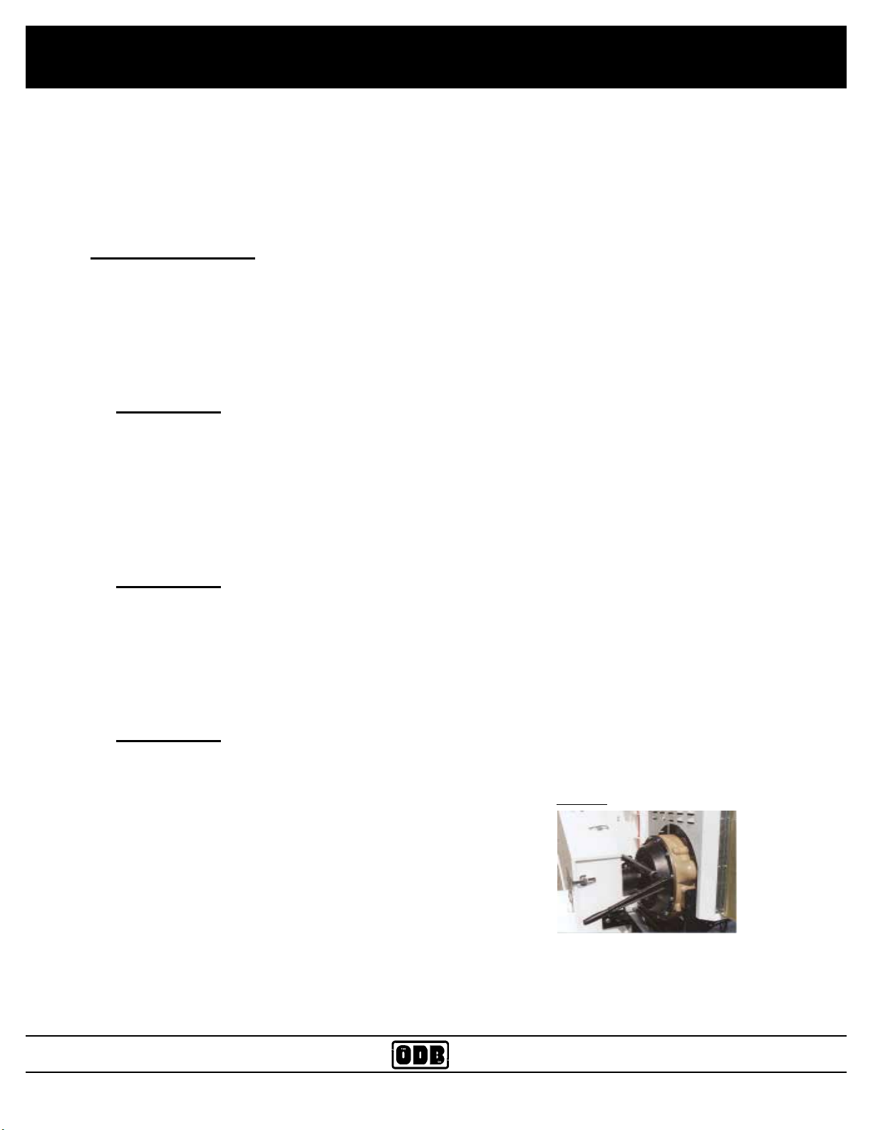
Always make sure the PTO is disengaged before
starting unit. (See gure 3b)
DO NOT start the engine in an enclosed building.
Proper ventilation is required before starting the
engine.
Thoroughly read and understand the safety and
pre-operating sections of this manual before staring the engine.
Throttle Control
The Module Uses J1939 throttle aka Torque Speed Control (TSC1)
PRIOR TO STARTING ENGINE, select the proper throttle control mode and parameters required for
application
Throttle is set through the Throttle Conguration Menu in the Control module
*Under CAN Conguration, you will nd Throttle Type Selection / TSC Min Speed / TSC Max Speed /
TSC Ramp Rate / Throttle Curve Selection*
Manual Throttle Options
1) Vernier Throttle
Standard Up and Down Throttle between the set Minimum and Maximum selections.
The Ramp rate is the rate of acceleration in RPMs per second.
2)Multistate Throttle
Provides for one, two, three, or four specic operating speeds. Pressing the Up and
Down Buttons adjusts engine speed between the selected multistate speed selections.
3) High/Low
Engine Accelerates to the Max Speed Setting with the Up button pressed. When the Up
button is released, the engine goes back to idle speed.
ODB COMPANY
800-446-9823 SKB700
27
Operating Section
3.1 Starting Engine, continued;
Review the Engine Operating Manual supplied with your leaf vacuum for specic start-
up, maintenance and operating instructions. It is especially important to review break-in
service procedures for brand new units.
Starting Procedure:
1. Perform all the pre-starting, pre-operating checks outlined in the EOM and in this
manual.
2. Make sure the PTO is disengaged as shown in gure 3a
3. IMPORTANT: Do not operate the starter for more than 30 seconds at a time.
To do so may overheat the starter. If the engine does not start the rst time,
wait at least 2 minutes before trying again. If the engine fails to start after 4 attempts, see the trouble shooting section of the EOM and this manual.
4. Turn the ignition switch all the way to the right, when the engine starts release the
ignition switch. It should spring back to the ON position.
5. IMPORTANT: If the ignition switch is released before the engine starts, wait
until the starter and the engine stop turning before trying again. This will pre-
vent possible damage to the starter and/or ywheel.
6. Check all gauges for normal engine opreration. If operation is not normal, stop the
engine and determine the cause.
7. IMPORTANT: To assure proper lubrication, operate the engine at or below
1200 rpm with no load for 1 -2 minutes. Extend this period 2 - 4 minutes when
operating at temperatures below freezing.
gure 3a
ODB COMPANY
800-446-9823 SKB700
28
Operating Section
3.2 Engine Controller-Installation
Engine must undergo a 60 deg warmup before clutch switch is live (active/useable)
Must Engage AND Disengage UNDER 1300rpms, anything over 1300 will not engage or
disengage
ECU Throttle Settings
Controls, Inc. panels use J1939 throttle, also called TSC throttle (torque/speed control). This is
different from the older analog and digital throttle options provided in engine ECU's. Two throttle
settings need to be implemented in the engine ECU.
1) TSC throttle needs to be enabled in the engine ECU settings
2) TSC address needs to be matched to control panel throttle setting
Most engine ECU today have TSC enabled as a default setting but for situation where it is not, the
engine ECU needs to be updated with this setting enabled. The control panel has a number of TSC
addresses that can be selected to match the engine ECU setting.
CAN bus Wires
With J1939 engines, all of the communications between the engine ECU and the control panel occurs over the two CAN bus wires. This includes the engine information (like oil pressure, engine
speed, alarm codes and alarm lamps) going from the engine ECU to the control panel and throttle
commands going from the control panel to the engine ECU. If there is a break in the CAN bus
wires, communications stop and the control panel displays a CAN bus error message. Also, in spark
ignition engines, CAN bus wires should located away from the spark plug wires, distributor cap and
ignition coil to avoid EMI from these high voltage components.
Proper Diode Installation
The proper installation of diodes protects the control panel and other electrical components (such as
the engine ECU) from transient voltage spikes generated whenever any relay (coil) in the system is
de-energized. See diode protection for more details. 1939 engine harnesses provided by the engine
manufacturer or Controls, Inc. follow proper diode protection specications.
Relay Outputs
Many of our products provide for relay outputs that can be used to drive other components and devices. These outputs are rated for a maximum current draw of 5 to 10 amps. For components or devices that draw more that this (such as a starter or glow plug circuit), it is necessary to install a slave
relay that is diode protected into the circuit. Controls, Inc. can provide any necessary slave relays.
ODB COMPANY
800-446-9823 SKB700
29

Operating Section
3.2 Engine Controller-Installation Cont.
Panel Throttle Settings
A number of panel settings are available in different Controls, Inc. panels. It is important to
check the throttle settings during installation. Basic settings for minimum speed, maximum
speed and ramp rate should be reviewed for a manual start situation. For an auto start situation,
other settings for warm up speed, operating speed and cool down speed should be reviewed.
Interlock Settings
Interlock settings provide the ability to turn relay outputs on and off based on conditions like
engine speed or engine run. They are typically used for clutch engage/disengage or to turn on/
off other devices when required during equipment operation. These settings need to be reviewed
during installation
Stored engine ECU codes can be viewed in the Stored Codes menu. The panel displays are codes currently stored on the engine ECU.
Alarm Log
All alarms and shutdowns are added to the control panel alarm log. The alarm log maintains the
last 32 alarms and faults. Each event is logged with the engine hour reading at the time of occurrence. This provides a history of alarms and shutdowns for mechanical engines that is valuable
for service and troubleshooting.
ODB COMPANY
800-446-9823 SKB700
30
 Loading...