

r-
..
,
O'
Day 222 & O'Oa
y 192 mastinthehorizontalpositionandthemainhat~hclosed,inserttheaft
mast base tabernacle pin and cotter ring. (See Fig, 3). Next push up and
. d " I .forward on the spar until the mast is in a vertical pos~tion. With one
Operating an Rigging nstructlons person holding the spar, attach the headstay to the forward hole in the
CAUTION: DO NOT BEGIN OPERATING OR RIGGING YOUR BOAT stemhead fitting with the clevis pin and cotter ring.. (See Fig. 5). Next put
UNTIL YOU HAVE READ ALL OF THE FOLLOWING OPERATING AND the fo~ward pin In the mast tabernacle and secure It with the cotter rIng.
RIGGING INSTRUCTIONS THOROUGHLY. ALSO SEE SAFETY IN. (See Fig. 3). After all stays are sec.ur~ly attach~d and the tabernacle pinS
FORMATION SHEET ENCLOSED WITH OWNER'S PACKET. are In, take the slack out of the rigging and tighten. Try to ensure even
pressure upon the mast step/tabernacle pinS In a fore & aft direction.
Safet y I nformation With the mast so positioned, the headstay, backstay, and two upper
sidestays should be tightened no more than hand tight. The two lower
THE MAST, THE STAYS. AND ALL OTHER PARTS of O'Day sailboats sidestays should be iust taut, not hand tight.
under 26 feet, following the general boating industry practice, ARE NOT
GROUNDED. Should your O'Daysailboat be struck by lightning or make CAUTION: IT IS VERY IMPORTANT THAT YOU DO NOT TIGHTEN THE
contact with electrical power lines, substantial injury or death may STAYS TOO MUCH, AS THIS CAN CAUSE DAMAGE TO THE HULl.. BE
result to the occupants, and substantial damage may result to the boat. SURE ALL LOCK NUTS ARE SECURELY TIGHTENED BY PLIERS OR A
We recom.mend that if you wish to attempt to minimize damage resulting WRENCH AND THEN TAPED TO PREVENT LOOSENING.
from lightning and provide a measure of safety for occupants, that you
have your O'Day sailboat grounded by an authorized O'Day dealer or After the stays have been adjusted, insert the cotter pins in the turnother "reputable boat yard in the manner recommend~d by the American buckle studs. (See Fig. 2). Bend the Fotter pins over and securely tape
Boat and Yacht Council of Amityville, New York. NOTE: That while the the cotter pins to prevent them from catching on anything
grounding system specified by the Council is the most widely accepted
lightning protection system known to us, we urge you to avoid exposing Attaching The Boom To The Mast
yourself to lightning, since no system will provide complete protection to Put the gooseneck, which is on the forward end of the boom. into the
the boat and its occupants in all circumstances. Whether or not your gooseneck fitting on the mast. (See Fig. 6). Attach with the provided bolt.
boat is grounded, when lightning is present in your boating area, DO Secure the aft end of the boom to the topping lift pigtail on the backstay.
NOT TOUCH THE MAST. BOOM, STANDING RIGGING, OR OTHER (See Fig. 4).
METALLIC OBJECTS. THESE ARE ALL ELECTRICAL CONDUCTORS,
WHICH WILL CARRY HIGH VOLTAGE AND CAUSE SEVERE SHOCK. Mainsheet
INJURY OR DEATH. Take the free end of the mainsheet, thread it through the upper sheave
, on the block attached to the triangular plate in the backstay, bring it up
The following is a list of standard equipment th~t comes with your boat. through the block on the boom. then back down to the bottom sheave
1. A mast with one set of spreaders. and thru the iam cleat. This type of mainsheet arrangement frees up the
2. A boom. cockpit considerably. Tie a figure eight knot in the end of the mainsheet
3. Flat package containing rudder and tiller. so you won't lose it. (See Fig. 4).
4. Box of rigging containing main halyard, jib halyard, st1jys, main sheet,
outhaul 'ib sheet and reef line. To Attach The Rudder.
5 B th' J
h .On the stern of the boat are two gudgeons Into whIch are Inserted the
.er cus Ions. .
d Af h dd h th tnse t". plntles on the ru der ter t e ru er IS ung on e ransom, I r
6. Sallbag containing mainsail and Jib and battens for the mainsail.
d I k . t.
h h I th b tt fth t tie
(See Fig 7)7 P b d th t I ff th b.the rud er oc pin In e 0 e In e 0 om 0 e op pin
.en oar s a sea 0 eca In. ..
...This IS to prevent rudder loss.
Suggested E.qulPment for Rigging Boat The rudder can be made to rise (kick up) by releasing the line which is
A medium sized screwdriver, a pair of pliers, p,.nd a'small roll of tape to cleated in the clam cleat under the tiller. (See Fig. 7). Be sure to keep the
cover the cotter pins. line tight and cleated while sailing or loss of control may result.
Optional Equipment -See your dealer on. what is''~V~ila.~!~. Optional To Hoist or Raise The Mainsail
equipment comes complete with Installation 1nstructlo~S where ap.
T th .
1 t th b tt .
th k t d ther bl 0 raIse e malnsal, Inser e a ens In elr poc e s. an n.
pica e. starting near the gooseneck, feed the foot of the sail clew first into the
Mast slot in the boom. The pin in the gooseneck fitting secures the tack of1he
The first step is to remove the plastic cover from the mast and remove sail. Draw the foot of the sail out along the boom until the foot is tight.
all protective padding. Remove the two spreaders which are taped on to The outhaulline is tied to the clew of the sail and passed aft on the boom
the mast. You will notice that these two aluminum tubes, or spreaders. through the block on the starboard side of the boom and forward to the
have a hole in one end and a fitting with a slot in the other end. These boom cleat approx. two thirds of the way forward on the boom (Figs. 4 &
.spreaders should be inserted in the spreader fittings about one-half way 9). The cleat is here to permit the crew to change the tension on the foot
up the mast The long cotter pin should pass through the hole in the of the sail while sailing.
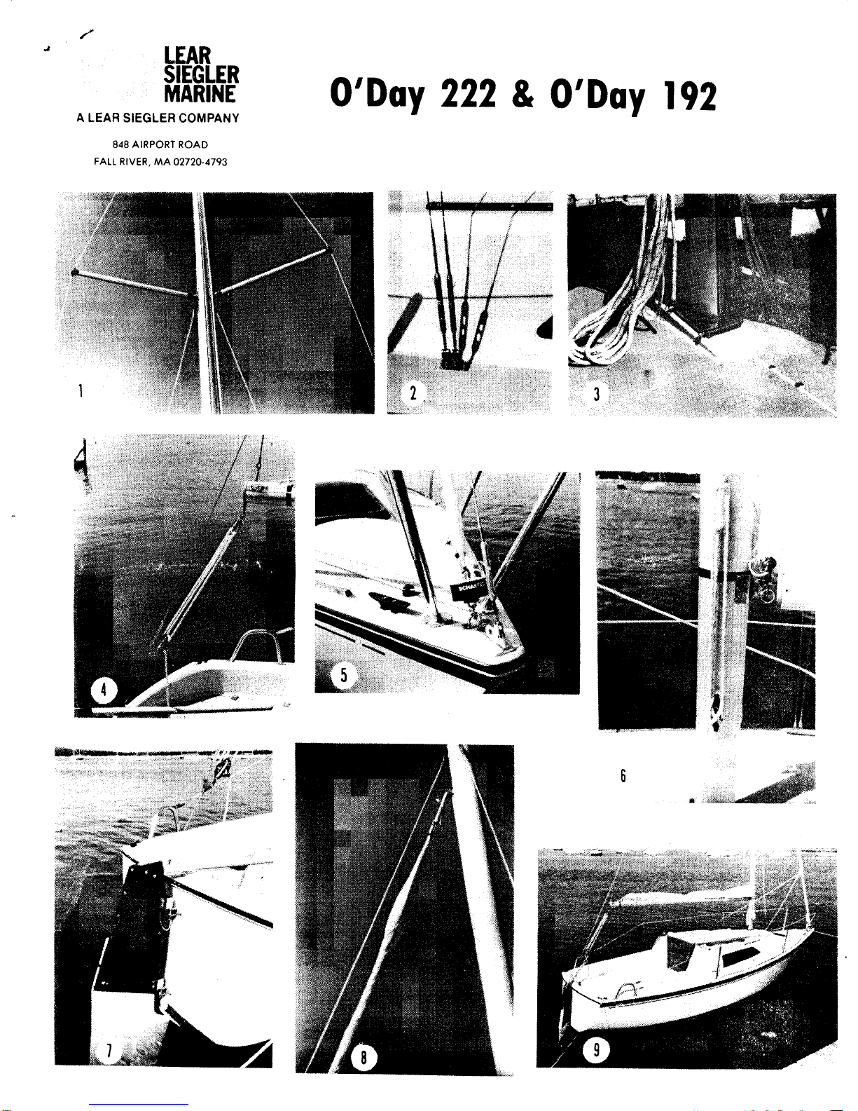
spreader and spreader fitting. See Fig. 1. Next, fasten the main halyard to the head of the sail and feed the luff
The upper sidestay passes through the outer spreader end. It rests in slugs of the sail into the stainless steel mast "gate" located above the
the slot. Stainless steel or monel seizing wire should be used to hold the gooseneck on the starboard side of the mast. Hoist the sail fully and then
wire in the slot. Tape both the spreader ends and bases well with rigging cleat the halyard. Then close the mast "gate" and tighten the knurled
tape. screw to hold it in place. The sail may then be lowered and furled (Fig
Before you step the mast, pull the shackles on the ends of the halyards 9)
to the foot of the mast and cleat the other end of the halyards to prevent To Hoist and Operate The Roller Furling Jib!
them from getting out of reach. The roller furling jib is designed to give ease of setting and furling of the
i Stepping the Mast jib. It is not designed to provide reefing
We recommend that you have assistance in stepping the mast. Open the The furling drum is pre.wrapped with the furling line at the factory
turnbuckles at ends of the stays to one-half open position. Then, attach Ten feet of the total of twenty-five feet should be wrapped in the drum.
the backstay to the stern chainplate with clevis pin and cotter ring, (See The drum is attached to the large pad eye aft of the stemhead fitting
Fig. 4), and proceed to attach sidestays, both upper and lower. to the (See Fig. 5) and the furling line is led aft through the black plastic
sidechainplates. The lower stays that go to the mast tangs located Just fairleads to the cockpit. The jib tack should then be attached to the top
below the spreader bases attach to the forward part of the chainplate of the drum with the clevis pin and cotter pin. (Fig. 5). The jib should be
and the upper stays that go over the spreaders attach to the aft part of in an unfurled (i.e. loose) condition at this time. Attach the supplied
the chain-plate. (See Fig. 2.). Do not attach the headstay yet. A taber. sheet to the clew of the jib by looping the middle of the sheet through the
na£le is provided on the cabin top for ease in mast stepping With the clew. leaving two loose ends of seventeen feet each Run the sheet ends
')
..
# outside the shrouds and then through the jib lead blocks on each side of Bilge Cover
the cabin top. Tie a figure 8 knot in the end of each sheet to prevent loss. The bilge cover in the cabin floor located over the keel is provided so
Next attach the upper swivel unit of the roller furling system to the head that any water in the hull can be pumped out. Be sure to check this area
of the sail. Be sure the "up" arrow on the swivel unit is pointing up. Next prior to sailing.
attach the jib halyard to the upper swivel and hoist the jib (Fig, 8). The Centerboard
jib halyard tension should be just slightly greater than the headstay The fiberglass centerboard is held in the centerboard trunk by a centension. This will allow proper furling of the jib and help prevent the jib terboard hanger that holds the board up and is inserted from the
tangling with the head stay, The jib can now be furled by pulling on the bottom of the keel, Should the centerboard need to be removed for
furling line. Keep light tension on one of the jib sheets while furling, Be replacement, repair, painting, or for pendant renewal, the hanger is
Sure that both jib sheets are free to run, If there is any resistance stop easily removed by unscrewing the fastenings that secure it in place on
pulling the furling line. Watch the sail as it is being furled to prevent the the bottom of the keel. In the forward end of the cockpit there is a
sail from wrapping around the forestay as it furls. Furling and unfurling centerboard pendant and cleat. To secure the centerboard pendant.
should always be done with the boat facing into the wind. To unfurl the simply wrap it around the cleat, Watch the pendant for wear and replace
jib, first uncleat the furling line and make sure that it is free to run. Face when necessary.
the boat into the wind and pull on the leeward jib sheet until the jib is
fully unfurled. Then recleat the furling line Boati ng Safety Act
We do recommend that the furling drum and halyard swivel,be washed A Federal Boating Safety Act was passed in 1971 to further
with fresh water every month. We also recommend that the lib be t~ken encourage safety in boating. Lear Siegler Marine certifies that it
down ,and stowed away I~ the boat, IS left.,fo~ an extended period of time, reasonably complies with requirements of the Act, There are
A furling cover. may be Installed If the lib IS to be,left up for extended several specific aspects of the Act new customers should un-
periods, This will help prevent ultra violet degradation to the sailcloth. derstand.
1. Every O'Day boat has a special numbering system. Numbers
CAUTION: THE FURLING DRUM AND SWIVEL IS ONLY DESIGNED are permanently molded into the transom on all models. The
FOR THE SUPPLIED LAPPER JIB. UNDER NO CIRCUMSTANCES first three letters are our manufacturing I D Code the next
SHOULD A LARGER SAIL BE USED WITH THIS UNIT. letter represents the boat model code lette.r, the' next four
numbers are the sail, class or hull number; the next letter and
Jiffy Reefing .number represent the month and year of manufacture; the last
Your"malnsal.1 can be easily reefed as your boat and sail ar~ equipped two digits represent the model year.
with jiffy reefing. To reef, release the main halyard slowly until th,e metal 2, Approved life saving devices are required for each crew
ring located about three feet up the mainsail luff can be hooked Into the member on board.
hook on the starboard side of the gooseneck. Then tighten the halyard 3. Availability of approved fire extinguishers is required on many
again, CAUTION WHEN THE MAIN HALYARD IS LOWERED, THE BOOM boats. Customers should consider having an extinguisher even
WILL FALL UNLESS RESTRAINED ~Y THE TOPPING LIFT PIGTAIL ON when not required.
THE BACKSTAY. Next,.the reefing line, which sh?uld be attached to the 4. Recommended horsepower for engines should be complied
eye on the starboard side of the boom approx. eighteen Inches forward with for safety and warranty reasons.
of the aft .end,of the boom, passed up through the grommet on the leech 5. After dark, boats must be lit in an approved fashion -
of the mainsail.. down through the, block on the port side of the bOOri', and customers must make provision for this.
forward to the cleat on the port side of the boom, should be pulled tight. 6. Lear Siegler Marine is obligated to inform customers of
You. ~ave now reduced the area of your mainsail by more th.an 20%. manufacturing defects which may exist in specific boats. Ob-
Addl~lonal small lines may be used to secure the excess mainsail, by viously, Lear Siegler Marine cannot do this readily without
running them through the three small grommets In the middle of the sail record of each boat's owner, which is supplied by return of the
and tYing them under the boom. Warranty Card, The Company strongly urges this Card be
returned promptly.
Outboard Motor
We recommend a maximum of 15 horsepower with a long shaft. The Genera II nformation
outboard motor is attached to the outboard motor bracket. We feel that Th f II ' '
f t'. t b d .d df4 8 h 'II b th d t e 0 owing In orma Ion IS 0 e use as a gul e an I you are
-PWI emore ana equa e, .
not sure or need more help, do not hesitate to call upon us or our
CAUTION: BE CAREFUL WHEN TURNING THE RUDDER BLADE AS IT dealer. ..' .
CAN COME IN CONTACT WITH THE PROPELLER. Tuning -~o not overtighten ~tays. ~s malnsheet tension w!11
dictate tension on headstay, While sailing, the leeward stays will
Trailer a!ways go slack due to mast .bend, stretching, etc., ~o under no
You will need a trailer that will support the complete boat's weight plus ~Ircumstances should you tl~hten the~ under sail -all ad-
20 per cent which will cover weight of normal gear. It is a good idea to justments should be made while at rest with the salls down.
pad all areas of the mast that come in contact with the boat and trailer, Maintenance
All halyards and stays should be securely fastened to the mast while Fiberglass Repairs -Although fiberglass is a relatively simple
trailering. Also be sure that the boat is securely fastened to the trailer material to work with, we urge that you familiarize yourself with
itself. The majority of hull weight should be in the keel support bed of the the proper procedures in order to insure good results.
trailer, The surface color (gel coat) should be cleaned and waxed at least
Do not have excessive weight on the two side supports, for ease in twice a year in order to maintain its luster. The color may fade
hauling and launching, and for proper weight distribution on the hull. due to weathering and if ordinary cleaning will not bring the
When launching your boat you will have to back the trailer into the water color back, try a regular automotive compound followed up by
and float the boat off. This can easily be done with any average-sloped waxing.
launching ramp. In salt water, be sure to wash the trailer down im- S"I D I .
mediately to minimize corrosion, If your trailer is equipped.with "bearing al s -ry an.d fo d carefully after each use and If used on ~alt
buddies," be sure to check for sufficient grease. water, wash with fresh water every so often. Fold by stretchl.ng
NOTE: Trailers rated for gross loads require a 2- inch trailer ball. (I.E" out the sail on the lawn or clean surface and starting at foot with
over 2,000 Ibs.) pe.rs~n at clew and tack, make one foot to two foot folds by
bringing the head down towards you gradually and evenly.
Sink Drain, Cockpit Drain and Centerboard Tube Hose Finally, fold from clew to tack or vice versa.
Be sure to check all conn.~ctions for water tightness. Hose clamps Preventive Maintenance -Be sure that the screws and bolts on
should be checked at each sailing. the tabernacle are periodically checked.
l
.'
~ W°O<!work- ." DOWNHAUL: A device used to tighten the luff of a sail.
VarnIsh at least once a year, using any good marine varnish. FAIRLEAD: An eye used to lead line in the direction desired.
Teak ca.n be either oiled or va~ni.shed. Teak should be oiled at FOOT: The lower edge of a sail.
least twice a year to prevent splittIng. GOOSENECK: A metal device that secures the boom to the mast.
Bottom Paint -recommended in both fresh and salt water. GUDGEON: A metal socket attached to the transom to receive the pintle
Follow directions on can -be sure to paint keel and cen- of the rudder. , ..
terboard as well as bottom. GUNWALES: The upper edge of a boat s side, where It meets the deck.
.HAL YARD: A line for hoisting (or raising) the sails.
Leakln.g -Should any .Ieaks develop through. ha~dware HEAD: The upper corner of a sail.
fastenIngs, hull and ~eck JoInts, etc., these can be easily fixed by HEADBOARD: The fitting at the head of a sail with a hole in it to receive
applYing a good marine sealant. the main halyard.
Trailer -Normally, any good marine boat trailer is sufficient HEADSTAY: The foremost stay on a sailboat. A jib is set on a headstay.
that will support the complete boat's weight plus approximately HULL: Main body of a boat.
20 percent which will cover the weight of normal gear. JIB: A triangular sail set forward of the mast.
F Th R JIB SNAPS: Small fittings that are attached to the luff of a jib which
T~~ ra~e ~fc~~e mast can be changed by adjusting the jib halyard secu~e the jib.to tile heads~ay. ...
and then re-adjusting the sidestays. In general, a boat will JIBE. The action of the mainsail when shifting from one side of the boat
perform better while sailing to windward with some aft rake and to the o:her, when heading d°:-vn wind.
better downwind with the mast plumb or slightly ra~~ed forward. LEECH. The after edge of a sail.
Races are usually won to weather, so favor more aft rake, if LEEWARD: Away from the wind.
th 'ng LINE: The common expression for a rope In use. .
an~ I .LUFF: The forward edge of a sail.
Sail S.et -.MAINSAIL: The principal sail on the mainmast.
The jib .halyard sho.uld be taken up so that the tenslo~ on the MAINSHEET: The line used to trim a mainsail.
luff, while und,er saIl, should be greater than t~at ~f t e head- MAST: An aluminum tube designed to stand on end so as to support a
stay. The tension on the foot and luff of .the m~lnsall should be boom plus one or more sails.
such that there are no .stre.ss lines or wrl.nkles. In the sail. Apply MASTHEAD: The top of the mast.
more tension as the wind In.creases, whIch will move the draft MASTHEAD FITTING: The fitting at the top of the mast.
forward and decrease heeling. mo~~nt, etc. In. ge~eral, the MAST STEP: A metal fitting that holds the base of the mast in position.
outhaul should be.slac~ened while sailing off the wind In order to OUTHAUL: A line used to haul the clew of a sail out to the end of the
create more draft In saIl. boom
Te!1 Tales are an invalua.ble aid i~ determining wind direction -PINTLES: Pins on the forward side of a boat's rudder designed to rest in
8 I~ch pieces of ~arn tied to sldestays 2 ft. to 4 ft. up from and pivot on the gudgeons secured to the transom.
ch.alnplate ~nd a wind pennant on top of mast. ...PORT: The left side of a vessel facing forward.
6 Inch to 8 Inch pieces of yarn taped t? luf! of Jib on both sides REEFING: To reduce a sail by rolling or folding up part of it.
every 3 feet or so on ~ottom half ?f sail 8 Inches back from .luff RIGGING: The wire supporting the spars is called standing rigging (stays
wire are excellent wlnd-flo~ gu!d~s. If you point too high, or shrouds) and the ropes used in setting and trimming sails are known
weather yarn flutters and If pointing too low, leewar~ yarn as running rigging (halyards and sheets).
flutters. Both should flow back evenly -remember this only RUDDER: A vertical plate attached to the stern of a boat used in
tells y.o.u flow pattern for a given jib trim, so trim must be correct steering it.
for sailing angle. SELF RESCUING: A feature which enables the crew to right and sail
Manufacturing Changes away a boat which has capsized.
leir Siegler Marine reserves the right to make specification and SHACKLE: A U-shaped piece 9f metal with a pin across the open ends.
design changes. If your boat is different from the enclosed in- SHEET: A rope used to trim a sail.
structions in any way, check with your dealer for correct SHROUD: Same as a stay.
procedrJres. SLACK: The opposite of taut. Slack away or off, to payout.
GI SLOOP: A one masted vessel with two or more sails.
ossa ry SPAR: A mast, a boom, etc.
AFT: In the neighborhood or direction of the stern. SPREADERS: Aluminum tubes that project from a mast in a traverse
BATTEN: A thin wooden or plastic strip placed in a pocket in the leech of direction in order to keep a stay at proper tension and to help hold the
a sail to help hold its form. mast erect.
BLOCK: Pulley consisting of a frame in which is set one or more sheaves STARBOARD: The right side of a boat, facing forward.
or rollers. Ropes are run over these rollers. STAY: A length of wire used to support a spar.
BOOM: Spar at the foot of the mainsail. STEMHEAD FITTING: The fitting nearest the bow on the deck where the
BOOM VANG: Tackle secured to the bottom of the boom about 3' aft of headstayattaches.
the gooseneck. The other block attaches to an eye at the base of the STEP: To step a mast is to set it in position.
mast. The vang's purpose is to keep the boom steady and horizontal STERN: The after part of a boat.
while sailing. TABERNACLE: A fitting designed so that the mast can be lowered when
BOW: The forward part of a boat. passing under obstructions; also facilitates stepping and unstepping the
CENTERBOARD: A keel like device that can be hoisted or lowered in a mast.
trunk that acts as a keel in shoal draft boats. TACK: The lower forward corner of a sail.
CENTERBOARD PENDANT: Line used to raise and lower centerboard. TILLER: A piece of wood connected with the rudder head. By this the
CHAINPLATES: Strips of metal fastened to the boat's hull near the deck rudder is moved as desired.
line to take the stress of stays. TOPPING LIFT: A wire and/or rope that attaches to the top of the mast
CLEAT: A fitting to which ropes are made fast. and fastens to the end of the boom. Its purpose is to hold the end of the
CLEVIS PIN: A small stainless steel pin that has a hole in one end for a boom up when the mainsail is lowered.
cotter pin and is used to secure stays to chainplates and mast fittings. TRIM: To trim sails. To put them in correct relation to the wind, by
CLEW: The aftermost lower corner of a sail. means of sheets.
COCKPIT: An open area lower than a boat's deck where the occupants TRUNK: A centerboard housing.
sit. TURNBUCKLE: A device used to maintain correct tension on rigging.
COTTER PIN: A straight or circular split metal pin used to hold a clevis WINDWARD: Toward the wind.
pin in place. March 1, 1985
~,
/"
.I LEAR
~i~~r O/Day 222 & O/Day 192
A LEAR SIEGLER COMPANY
848 AIRPORT ROAD
FALL RIVER, MA 02720-4793
1
6
.
 Loading...