


www.odacore.com
Programmable DC Power Supply
OPS Series
User Manual
Manual Part NO. 018OPS-2.0

Legal Notices
© ODA Technologies.,Co.Ltd 2004
No part of this document may be photocopied, reproduced, or translated to another language without
the prior another language without the prior agreement and written consent of ODA agreement and
written consent of ODA Technologies.,Co.Ltd. as governed by Korea and international copyright laws.
Warranty Certification
The material contained in this document is provided “as is,” and is subject to being changed, without
notice, in future editions. Further, to the maximum extent permitted by applicable law, ODA disclaims
all warranties, either express or implied, with regard to this manual and any information contained
herein, including but not limited to the implied warranties of merchantability and fitness for a particular
purpose. ODA shall not be liable for errors or for incidental or be liable for errors or for incidental or
consequential damages in connection with the furnishing, use, or performance of this document or of
any information contained herein. Should ODA and the user have a separate written agreement with
warranty terms covering the material in this document that conflict with these terms, the warranty terms
in the separate agreement shall control.
Assistance
This product comes with the standard product warranty. Warranty options, extended support contacts,
product maintenance agreements and customer assistance agreements are also available.
Contact your nearest ODA Technologies. Sales and Service office for further information on
ODA Technologies. full line of Support Programs. Refer to below information.
www.odacore.com
oda@odacore.com
82-2-1800-8644
Waste Electrical and Electronic Equipment
The affixed product label (see right) indicates that you must not discard
this electrical/electronic product in domestic household waste. Do not
dispose in domestic household waste. To return unwanted products,
contact our local ODA distributors, or call us for more information.
Manual Editions
Manual Part Number: 018OPS-2.0 Edition 2, February, 2018 Printed in ROK
Reprints of this manual containing minor corrections and updates may have the same printing date.
Revised editions are identified by a new printing date.

Safety Notices
p
d
p
y
The following general safety precautions must be observed during all phases of operation of this
instrument. Failure to comply with these precautions or with specific warnings or instructions elsewhere
in this manual violates safety standards of design, manufacture, and intended use of the instrument.
ODA Technologies assumes no liability for the customer's failure to comply with these requirements.
eneral Do Not Modify the Instrument
G
Do not use this product in any manner not
specified by the manufacturer. The protective
features of this product may be impaired if it is
used in a manner not specified in the operation
instructions.
Do not install substitute parts or perform any u
nauthorized modification to the product. Return
the product to an ODA Sales and Service Office
for service and repair to ensure that safety
features are maintained.
round the Instrument
G
This product is a Safety Class 1 instrument
(provided with a protective earth terminal).
To minimize shock hazard, the instrument unintended o
chassis and cover must be connected to an qualified service personnel.
electrical ground. The instrument must be
connected to the ac power mains through
a grounded power cable, with the ground
wire firmly connected to an electrical ground
(safety ground) at the power outlet. Any attention to an operating procedure, practice, or
interruption of the protective (grounding) the like that, if not correctly
conductor or disconnection of the protective to, could result in damage to the product or loss
earth terminal will cause a potential shock
hazard that could result in personal injury. C
Before Applying Power are fully understood and met.
Verify that all safety precautions are taken.
Make all connections to the unit before W
applying power. Note the instrument's A WARNING notice denotes a hazard. It calls
external markings described under attention to an operating procedure, practice,
Fuses death. Do not proceed beyond a WARNING
The instrument contains an internal fuse, which notice until the indicated conditions are fully
is not customer accessible.
n Case of Damage
I
Instruments that appear damaged or defective
should be made inoperative and secured against
eration until they can be repaired b
AUTION
C
AUTION notice denotes a hazard. It calls
A C
erformed or adhere
of important data. Do not proceed beyond a
AUTION notice until the indicated conditions
ARNING
rofrep yltcerroc ton fi ,taht ekil eht ro "slobmyS ytefaS" med or
adhered to, could result in personal injury or
understood and met.
D
o Not Operate in an Explosive Atmosphere
Do not operate the instrument in the presence
of flammable gases or fumes.
D
o Not Remove the Instrument Cover
Only qualified, service-trained personnel who
are aware of the hazards involved should
remove instrument covers. Always disconnect
the power cable and any external circuits before
removing the instrument cover.
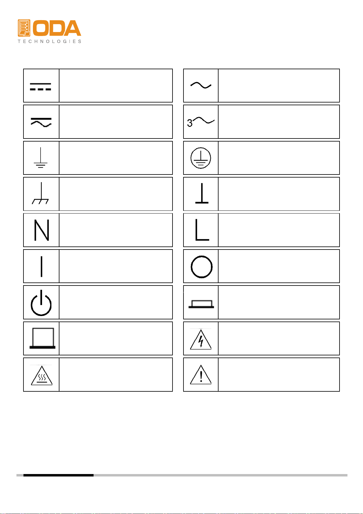
Safety Symbol
Direct current
Both direct and alternating current Three phase alternating current
Earth (ground) terminal
Frame or chassis terminal
Neutral conductor on
permanently installed
equipment
Alternating current
Protective earth ground terminal.
Terminal is at earth potential.
Line conductor on
permanently installed equipment.
Standby supply. Unit is not
completely disconnected
from ac mains when switch
is off
Out position of a bi-stable
push switch
Caution, hot surface
ylppus ffO ylppus nO
In position of a bi-stable push
switch
Caution, risk of electric shock
Caution, refer to accompanying
documents

CONTENTS
-
R
p
-
-
n
-
-
Default Setti
-
-
-
-
-
-
gp
1. General Information
1-1. Feature
General Feature
emote Interface
Calibration
Factory Option
Cycling Mode
Self Testing
---------------------------------------------
--------------------------------------
1-2. Accessories and Options
Accessories
O
tions
1-3. Check
Instrument Check
electrical Check
1-4. Operating Conditions
------------------------------------------------
-------------------------------------
1-5. Check Before Power On
Output Terminal check
Power Cord check
Input Power Line Check
1-6. Check After Power O
Display Procedure on the LCD
ng Values
1-7. Installation
Cooling
Bench Operation
Rack Mounting
---------------------------------------------
-------------------------------------
---------------------------------
-----------------------------------
6
6
7
8
8
9
11
12
2. Front Panel, Rear Panel Composition & Function
2-1. Front Panel Voltage & Current Setting
2-2. Display & Condition Indicator LAMP
2-3. Rear Panel Composition
2-4. Output Check
Voltage Output Check
Current Output Check
-------------------------------------------
-----------------------------------
- 2 -
----------------------
------------------------
---------
14
17
18
19
20

3. Front Panel Operating
-
-
33. Remote Voltage Sensing
24
-
3-5. P
(OCP)
29
-
37. KEY LOCK
36
F
-
LMT DISPLAY Function
-
SEQUENCE Number input
-
-------------------------------------- 21
Over view
3-1. Constant Voltage Operating(CV)
3-2. Constant Current Operating(CC)
-
CV Regulation
Output Rating
Output Noise
Stability
Connecting Remote Voltage Sensing
-----------------------------------
---------------------------
---------------------------
3-4. Programming Over Voltage Protection(OVP)
rogramming Over Current Protection
3-6. I/O Config & LOCAL
RS232C Setting
RS232C Setting(Option)
GPIB Setting
GPIB Setting(Option)
-
---------------------------------------------
3-8. STORE / CALIBRATE
3-9. RECALL / FACTORY
3-10. OUTPUT ON/OF
3-11. V/I & LMT DISPLAY
V/I Function
--------------------------------------
--------------------------------------
--------------------------------------
----------------------------------------
--------------------------------------
-----------------
-----------------
22
23
26
31
37
38
38
39
3-12. CYCLING MODE
Feature
Preparing Record Table
STEP
STEP Setting
SEQUENCE
REPEAT
REPEAT input
RUN / STOP
RUN / STOP Proceed
3-13. ERROR
ERROR Check
3-14. ESC
------------------------------------------------
---------------------------------------------------
----------------------------------------
40
47
47
- 3 -

4. CALIBRATION
g
-
-
-
44. Calibration Technique
49
Positioning Calibrating Location
Positioning Calibrating Location
-
4-6. Calibration(for GPIB) Using REMOTE INTERFAC
57
-
Y
-
-
-
-
E
-
-
4-1. Function
4-2. Preparing for Detailed Setting
---------------------------------------------
------------------------------------------------
-------------------------------48
4-3. Required Efficiency for Detailed Settin
-
Instrument Connection
Electronic Load
Current-Monitoring Resistor(shunt)
DVM(Digital Volt Meter)
Programming
--------------------------------------
----------------------
48
48
49
4-5. Calibration Using Front Panel
CALIBRATE KEY Structure
CALIBRATE Setting Area
Voltage CALIBRATE Operating
Current CALIBRATE Operating
Conneting Instrument
Remote Calibration Command Sequence
Voltage CALIBRATE Operating
Current CALIBRATE Operating
5. FACTOR
5-1. Feature
------------------------------------------------
------------------------------------------------
5-2. FACTORY KEY Structure
5-3. CYCLING CLEAR
CYCLING CLEAR Operating
5-4. USER-MEM CLEAR
USER-MEM CLEAR Operating
5-5. CALI-RESTOR
CALI-RESTORE Operating
5-6. CALI-BACKUP
CALI-BACKUP Operating
----------------------------------------
--------------------------------------
-------------------------------------------
-------------------------------------------
---------------------------
---------------
---------------
-----------------------------------
51
59
59
59
59
60
61
62
- 4 -

6. SCPI Command
s
x
-
-
-
65
-
-
64. Output Voltage & Current & Operating Commands
65
d
d
-
-
-
-
r
o
-
-
-
-
-
7-5. Calibrati
r
77
-
-
-
-
-
-
-
-
-------------------------------------------
6-1. Commands Synta
6-2. Commands
Output Setting Commands
Measurement Commands
Calibration Commands
Factory Commands
System Commands
6-3. Apply Comman
---------------------------------------------
-------------------------------------------
6-5. Measure Commands
6-6. Calibration Comman
6-7. Factory Comman
6-8. System Command
----------------------------------------
------------
-------------------------------------
-------------------------------------
----------------------------------------
----------------------------------------
63
63
63
65
69
70
71
71
7. Error Messages
7-1. Running Error
7-2. Hardware Error
-------------------------------------------
-------------------------------------------
-------------------------------------------
7-3. Remote Calibration Erro
7-4. Cycling Mode Err
on Erro
----------------------------------------
----------------------------------------
7-6. Fixed Memory Check Error
7-7. Interface Commands Error
8. Option
8-1. Analog Input
8-2. Rear Output
9. Specifications
-------------------------------------------
-------------------------------------------
-------------------------------------------
-------------------------------------------
-----------------------------------
--------------------------------
--------------------------------
75
75
75
76
77
78
78
80
80
81
82
10. Caution
------------------------------------------------
- 5 -
85

1. General Information
instrument) protocol. In addition, It is designed to be equipped in 3U*19inch Half-Rack
▌
▌Insulation with instrument & Floating Logic realization
▌Store Voltage, Current, Slope time, Delay time each step up to 100 slots
▌
1-1. Feature
ODA Technologies's OPS-Series are high efficiency, high performance programmable DC power supply
RS232C & GPIB(IEEE-488.2) interface based on SCPI (Standard Commands for Programmable
*
General Functional Features
▌Simple setting using jog & shutttle.
▌Output voltage, current block & restore function (Output ON/OFF)
▌Front panel's key lock function
▌Caution alarms on events
High accuracy & High limit of resolution
▌Built-in Remote Sensing for Load Voltage(V-Sensing)
▌Over Voltage Protection(O.V.P) / Over Current Protection(O.C.P) Secure Function
▌Excellent Load Regulation & Line Regulation
▌Operating condition(Voltage,Current,OVP,OCP) Store & Recall up to 10 slots.
▌Store Error message (up to 10 messages)
▌3U * 19inch Half-Rack compatible
Remote Interface Features
▌GPIB(IEEE-488.2) & RS232C Interface
▌SCPI(Standard Commands for Programmable Instruments) compatible
▌High speed setting & measument
▌plenty of Commands equipped
▌Simple interface setting using front panel I/O config
▌Insulation with instrument & Floating Logic realization
▌SCPI programming grammatical order check options equipped
-
.
Calibration Features
▌adopted Software Calibration do not requires inside correction
▌Simple calibration operating using Independence or PC Interface
Factory Function Features
▌Initialization memory function up to 10 memories
▌Initialization mamory function up to 100 cycling mode memories
▌Calibration restoration function
▌Calibration back up function
Cycling mode Features
▌Operating realization by instrument itself
▌Safe storation used by permanent memories
▌Cycling mode tests available using sequence panel
Self Test Features
▌Front panel Test ▌ADC H/W Error Test
▌Remote interface Test ▌UnRegulated condition Test
Memory data verification Tes▌ADC/DAC Calibration verification Test
- 6 -

1-2. Accessories and Options
Function that blocks Voltage/Current in OUTPUT OFF Mode
Accessories
▌1 Power Cord
▌Output load (+), (-) 1 each. (Part number : OE-LW-BCW-2.0)
▌2 pcs metal short-bar for voltage sensing. (Part number : OM-S20)
▌1 User's Manual
▌DEMO Software CD (Windows application manual included)
Option
▌GPIB Module
▌GPIB Calbe 1M, 2M, 4M
▌RS232C Cable 1M, 2M, 4M, 10M
▌100V ± 10% , 50~60Hz AC input power
▌115V ± 10% , 50~60Hz AC input power
▌230V ± 10% , 50~60Hz AC input power
▌Rear output
▌Rack mount support
▌Block system when it is overlapped.
Function that blocks Voltage/Current in "**OUTPUT OFF**" Mode.
.
- 7 -

1-3. Check
Technologies in the future. If you return the power supply for service, attach a tag
▌Check the panel surfaces are free of dents and scratches
▌Wh
ODA
▌
▌Relative Humidity : Less than 80%
When you receive your power supply, inspect it for any obvious damage that may have
occurred during shipment. If any damage is found, notify the carrier and the nearest ODA
Sales Office immediately. Warranty information is shown in the front of this manual. Keep
the original packing materials in case the power supply has to be returned to ODA
identifying the owner and model number. Also include a brief description of the problem.
Mechanical Check
▌Check the broken key, encoder switch, power switch.
▌Check the broken output terminals.
.
▌Check the cabinet is free of scratches.
▌Check the LDC display is not scratched or cracked.
Electrical Check
en turning on the power, it shows instrument model and
▌Check the model Number is matched with displayed model number.
website at first.
▌After, it shows "**OUTPUT OFF**" message, verifies to a high level of confidence
that the power supply is operating in accordance with its specifications.
Note
Service Center : 82-32-623-5454
Home page : www.odacore.com
1-4. Operating Conditions
This instrument is designed for following environmental conditions in other to use
optimized condition
▌Environment Temperature : 0 ∼ 40℃
Relative Humidity : Less than 80%
▌Operating Altitude : Less than 2000m
▌No Vibration
▌Avoid Electric Magnetic Field
- 8 -
1-5. Check Before Power On
electric shock hazard to the operator
pp
a
a
and the worker
<Diagram 12>
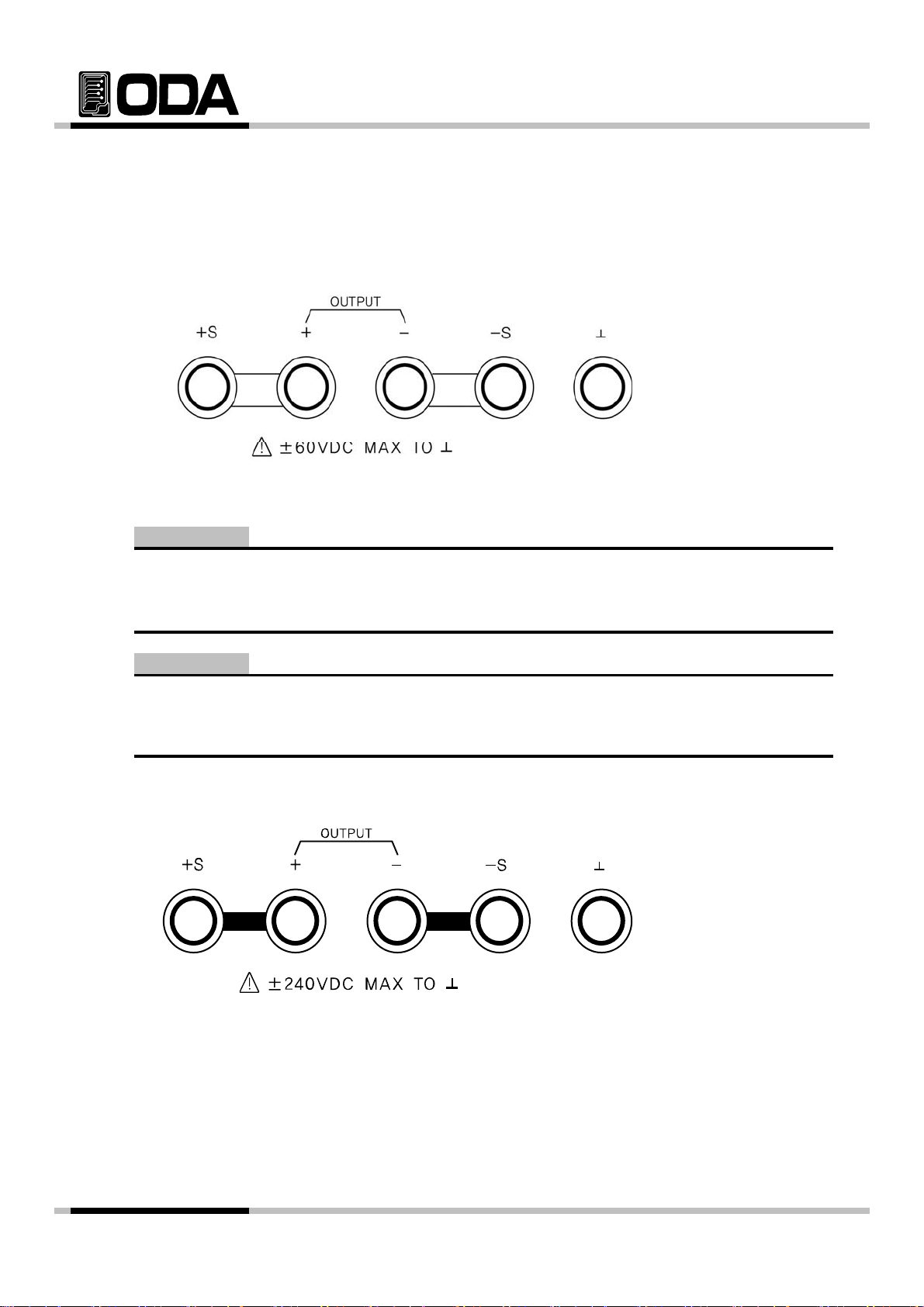
Output Terminal Check
▌Check the front panel two fixed outputs two variable output terminals and GND terminal.
Metal Short-bar
<Diagram 1-1>
WARNING
Floating the power supply output more than ±60 Vdc from the chassis presents an
.
WARNING
If metal short bar that is su
floated. Please make sure that there should be no contact between insulated output termin
.
insulate-bar
lied from our company excluded, maximum ±240Vdc output c
-
- 9 -
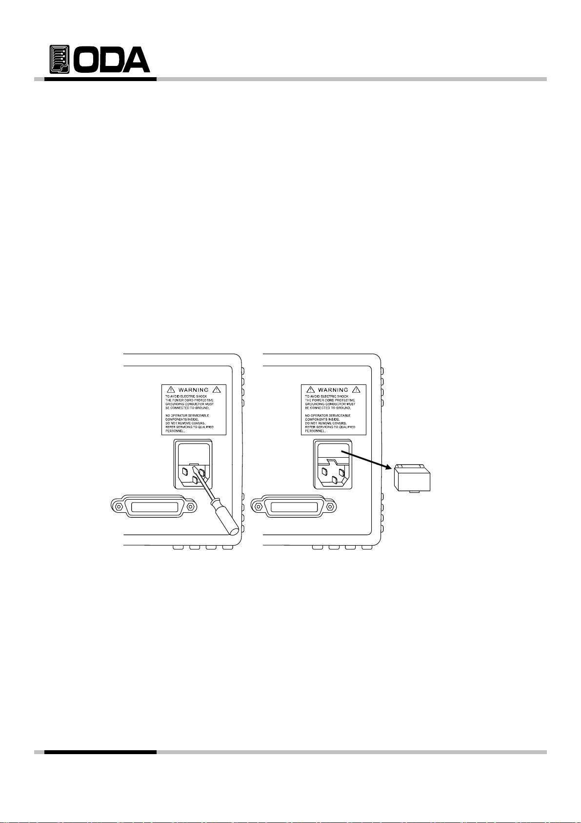
Power Cord Check
▌In other to prevent the instrument severe damage from overload, fuse is installed
▌Your power supply is equipped with a 3-wire grounding type power cord; the third
conductor being the ground. The power supply is grounded only when the powerline
cord is plugged into an appropriate receptacle. Do not operate your power
supply without adequate cabinet ground connection.
Input Power Line Check
▌You can operate your power supply from a nominal 198~242 V single phase ac
power source at 47 to 63 Hz. AC100V, 110V, 115V, 230V input power is optional.
Refer to chapter "1-2. Accessories & Options"
in inlet case. If the fuse is also repeatedly when power turns on, check the
input power line or broken braker and then call to nearest ODA Technologies A/S Center
Input power connection is following.
<Diagram 1-3>
- 10 -

1-6. Check After Power On
t
▌Output Voltage : 0V
▌Cursor Location : Default Voltage Select
pppypp
When turning on the power switch, the front-panel display will light up briefly while the
instrument performs its power-on default value setting. And also keep the ex-remote
interface setting mode, voltage value is zero and current value is max value.
OVP & OCP will be set on maximum output value.
Display Procedure on LCD
▌Homepage "WWW.ODACORE.COM" will be displayed.
Visit our homepage and we will provide various service and info about upgrading, manual and software.
▌Also, Front lamp OVP, OCP, LOCK, RMT will be all lighted.
CV & CC are not included.
▌"INITIALIZING. . ." Message will be displayed.
There will be a reset using non-volatile memory.
▌Also, Front lamp OVP, OCP, LOCK, RMT lights will be turned off.
CV & CC are not included.
▌"SELF-TESTING. . ." Message will be displayed.
While self-testing, message below will be displayed.
Front panel Tes
Remote interface Test Check Remote interface for PC network
Memory data verification Test Check Instrument's info & setting
ADC H/W error Test Check ADC controlling
UnRegulated condition Test Check Output voltage Floating
ADC/DAC Calibration Test Check ADC & DAC Calibration Data
When an error occurs, there will be a alarm sound from instrument, and error No will be stored.
Check Front panel's connection
Press Key to check error code.
Please read “7. Error Messages” to check details about error code.
Default Setting Value
▌OVP : OVP Max value, OVP setting ON ▌Remote Interface : maintain previous setting
▌OCP : OCP Max value, OCP setting ON
▌Output Current : Limit setting max value Voltage : 1V scale
▌KEY LOCK : OFF Current : 5A > 100mA scale
▌Condition after Self-testing : "**OUTPUT OFF**"
50A > 1A scale
Note1
The RS232C is attached in the instrument when the power supply is shipped from the
factory for remote interface configuration and baudrate is set 9600bps at first time.
In case of choosing RS485 interface, address no. is 05 when this is shipped from the factory.
Note2
It has the option function that is last setup stated memory & recall. This function, when you
turn down the instrument, the device store the last state(voltage, current and state) and after
then the operator turn on again, this starts from last state.
- 11 -
1-7. Installation
40 °C
pply by d
▌Y
ppl
fficient sp
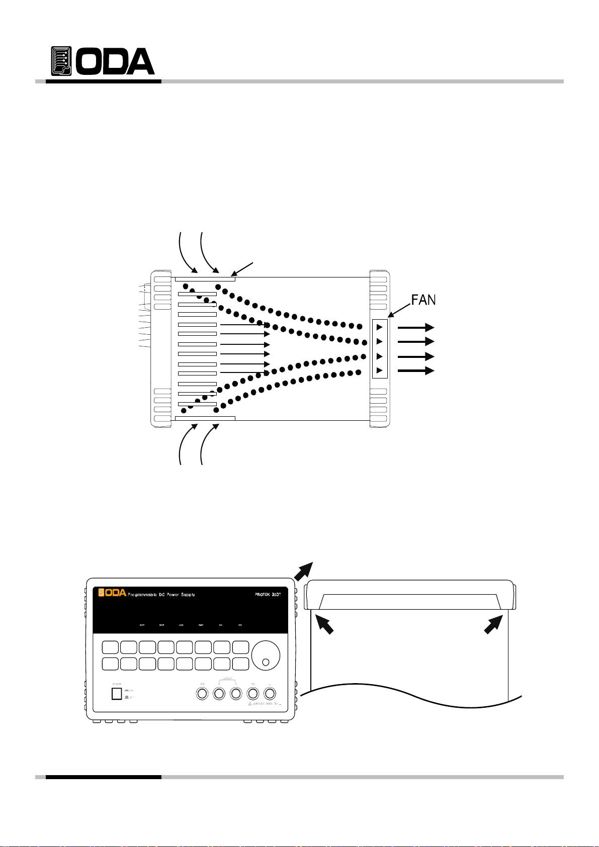
Cooling
▌The power supply can operate without loss of performance within the
temperature range of 0 °C to 40 °C, and with derated output current from
to 55 °C. A fan cools the power su
panel and exhausting it out the sides. Using an ODA rack mount will not
impede the flow of air.
Draft
rawing air through the rear
<Diagram 1-4 Bottom view>
Bench Operation
our power su
at the sides and rear of the power supply for adequate air circulation.
y must be installed in a location that allows su
ace
Rack Mounting
▌It is designed to be compatible in 3U * 19inch, please desort bumper (diagram below)
<Diagram 1-5>
- 12 -
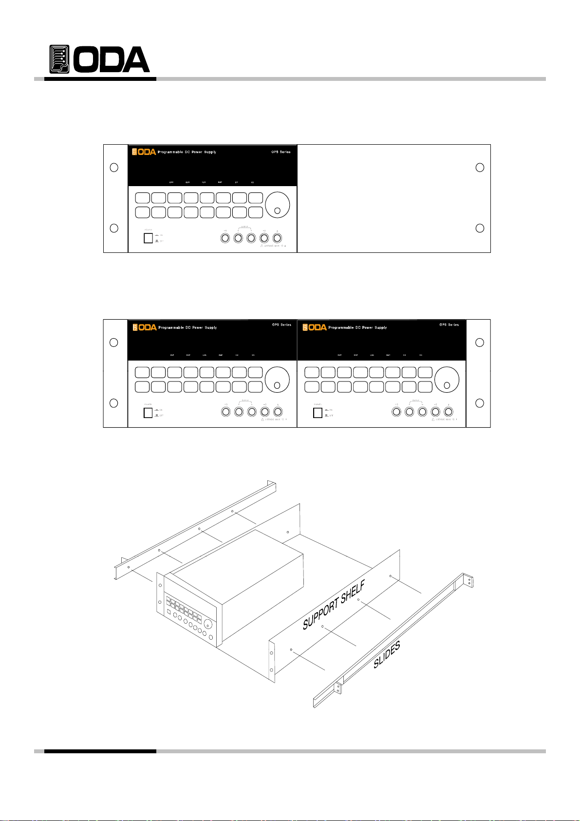
▌It is convenient to equip OM-3U19-FS(Option) supported by Power Supply indenpence
on the rack.
<Diagram 1-6>
▌It is convenient if you equip power supply double on a rack with OM-3U19-FD(option).
<Diagram 1-7>
▌It is simpler to use instrument if you use inside cabinet & slider OM-3U19-SS(Option).
<Diagram 1-8>
- 13 -
2. Front Panel, Rear Panel Composition & Function
y
e
p
6
19
13
Restore memory save slot or Factory Key
K
i
y
y
+ output terminal
13 Cycling mode s RUN/STOP Key
Over Voltage Protection Key Error message Display Key
114
Over Current Protection Key
215
I/O CONFIG or LOCAL Key
316
LOCK Key
417
Store present condition or Calibration K
518
Restore memory save slot or Factory Ke
Output Voltage/Current ON/OFF
720
Choice Voltage/Current or Limit Display
821
922
Cycling mode's STEP setting Key
10
Cycling mode's Sequence control Key
11
Cycling mode's repeating Key
12
C
cling mode's RUN/STOP Ke
Menu Escape Key
Voltage/Current Cursor or Menu Key
Main Power ON/OFF Switch
Remote V+ Sensing Input terminal
+ out
- output terminal
Remote V- Sensing Input terminal
Earth GND terminal Voltage/Current/Numbering Encorder Sw
ut terminal
- 14 -

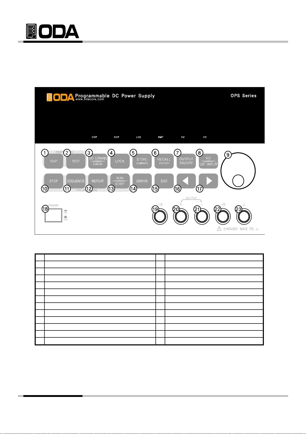
1. Over Voltage Protection Key
yp
i
pp
t
Over voltage protection function. On/Off selectable, able to change OVP Level value.
2. Over Current Protection Key
Over current protection function. On/Off selectable, able to change OCP Level value.
3. I/O CONFIG or LOCAL Key
Configures the power supply for remote interfaces. Set baudrate of RS232C. If remote
interface is RS485, it can be used for setting baudrate & address. Also under Remote Interface
situation, in other to recover bench top using, this key operate to local from remote.
4. LOCK Key
Lock/Unlock Key on the Front panel
5. Store current condition or Calibration Key
Store Voltage, Current, OVP / OCP Setting value. Press Power button while holding this key. Th
lead you in Calibration mode, voltage/current Calibration.
6. Memory save slot restoration or Factory Key
Saved Voltage, Current, OVP/OCP Setting value can be a
while holding this key. This will lead you in Factory mode, which allows you to restore or reset
calibration.
lied to instrument. Press Power but
7. Output Voltage/Current ON/OFF
Enables or disables the power supply output. This key toggles between on and off.
8. Voltage/Current select or Limit Display Key
Shows voltage and current limit values on the display and allows knob adjustment for setting
limit values.
9. Voltage/Current Cursor or menu changing key
Move the blinking digit to the left. In the menu mode, it can change menu tree.
Under the **OUTPUT OFF** mode, this key work on recall key.
10. Cycling mode's STEP setting Key
Appoint 1~100 slots, Set Voltage, Current, Slope Time and Delay Time.
11. Cycling mode's Sequence control Key
Setting repeating panels from ( )slot to ( )slot.
12. Repeating setting key of Cycling mode
Setting No. of repetition.
13. Cycling mode's RUN/STOP Key
Operate or Cancel Cycling mode after setting 10 → 11 → 12.
- 15 -

14. Error message Display Key
g
gggy
When error occurs from Self-testing, Alarm sound will come out from the instrument, and will b
up to 10 memories slot
15. Menu Escape Key
Canceling while in the Menu.
16. Voltage/Current Cursor or menu changing Key
Move the blinking digit to the left.
In menu mode, it can change menu tree.
Under the "**OUTPUT OFF**" mode, this key work on store key.
17. Voltage/Current Cursor or menu changing Key
Move the blinking digit to the left.
In menu mode, it can change menu tree.
Under the "**OUTPUT OFF**" mode, this key work on store key.
18. Main Power ON/OFF Switch
This switch allows to disable AC Power.
19. Remote V+ Sensing input terminal
+ Output Voltage sensing input terminal
20. + Output terminal
+ Output terminal.
21. - Output terminal
- Output terminal.
22. Remote V- sensing input terminal.
- Output Voltage sensing input terminal.
23. Earth GND terminal
GND terminal, it is able to connect to earth terminal of the DUT
- 16 -
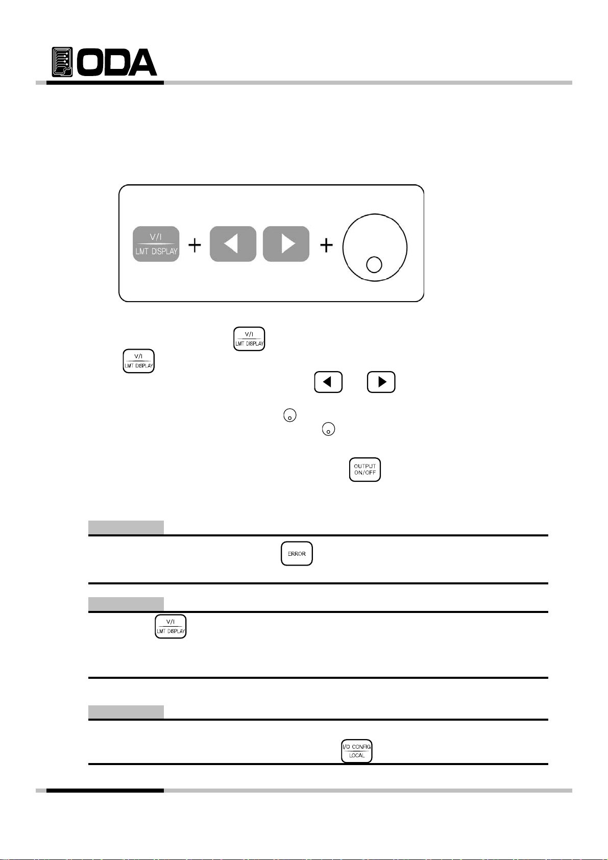
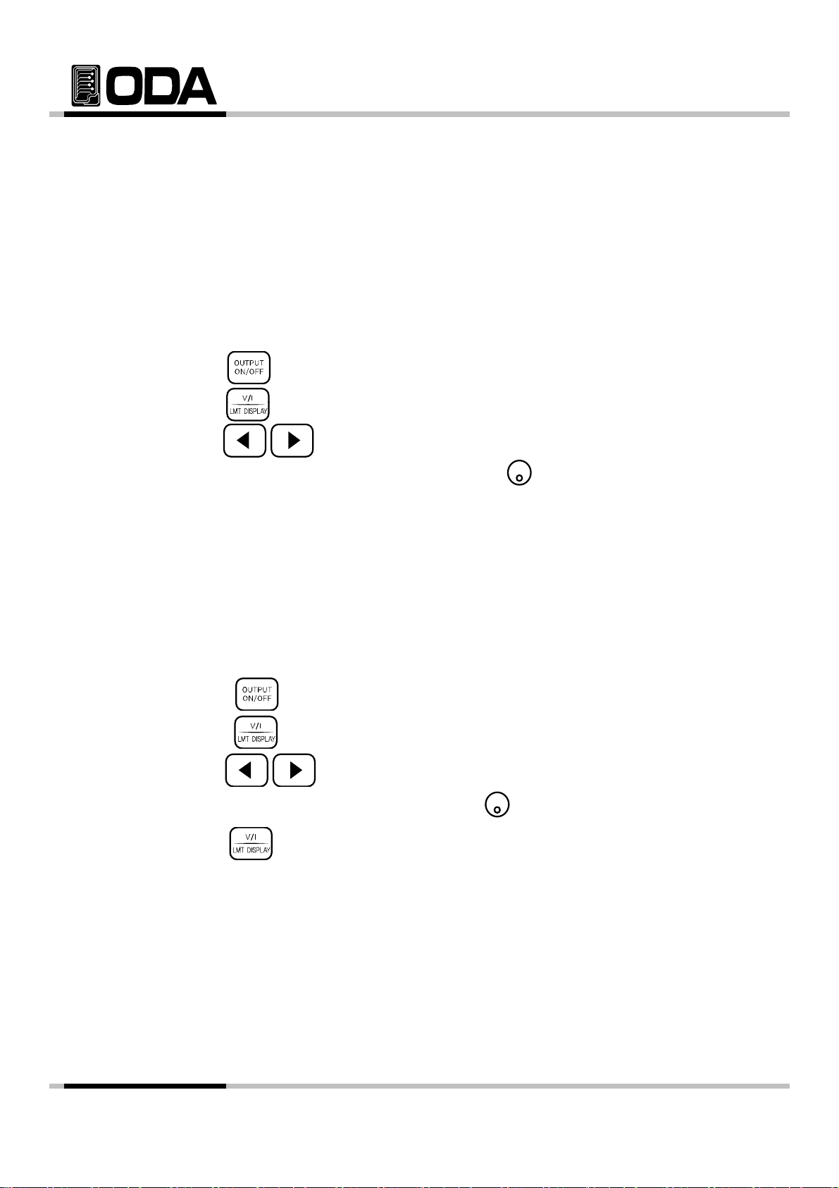
2-1. Front-Panel Voltage & Current Setting
Use the method below to change limit value of voltage and current.
1. Check "**OUTPUT OFF**" When the instrument turned on
2. Press V/I & LMT DISPLAY key to switch Limit Mode.
3. Press key to select Voltage and Current
4. To select incresing or decreasing digit, press or and position cursor key.
5. In other to increase limit value, turn the encoder clockwise.
In other to decrease limit value, turn the encoder anti-clockwise.
6. Confirm the change of setting value at VFD Display
7. In other to output the setting voltage & current, press key.
Note1
If there is a problem in "Self-test" Press key to confirm the error code.
Please check "7. Error Messages" for Error code.
Note2
When press key, disappear the message of "**OUTPUT OFF**" and then change to limit
display state, and cursor is blinking. At that time, if let the display time-out after 3 seconds,
**OUTPUT OFF** display at the LCD.
Note3
If it is under remote control, key and encoder switch on the front panel won't operate.
If turning to local mode from remote control, press key to change to local mode.
- 17 -
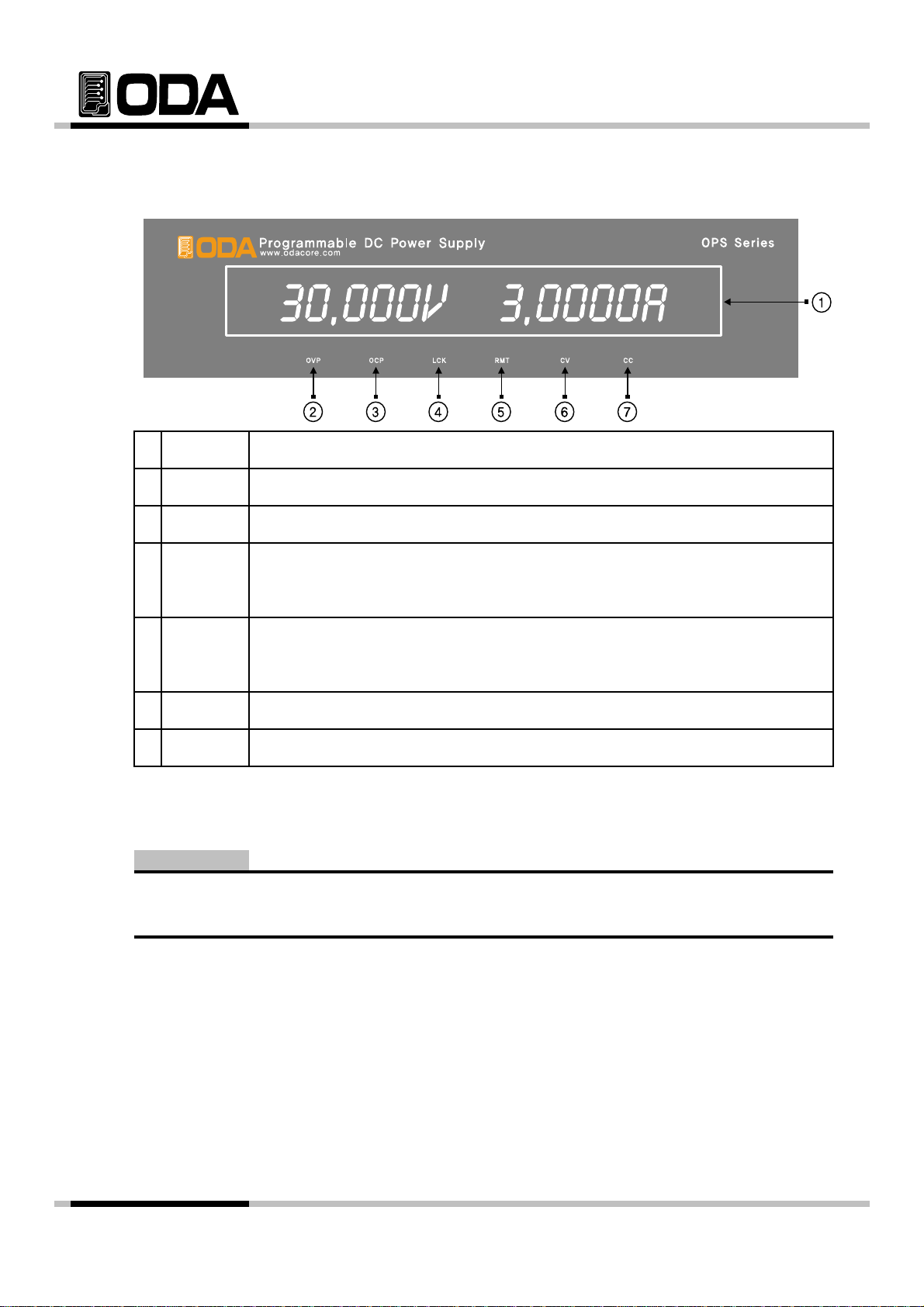
2-2. Display & Condition Indicator LAMP
p
e
p
e
1
2
3
4 LOCK
5 RMT
6
7
VFD
OVP
OCP
CV
Voltage Current & Message Display module
OVP Setting mode "Brightened bulb"
OCP Setting mode "Brightened bulb"
When it is
the light will go out and ables Key & Encoder.
In other to switch the dis
while the light bulb is ON.
Lights ON while Constant Voltage Mode.
Lights ON while Constant Current Mode.CC
ressed, Key & Encoder will disabled, when it is pressed onc
lay to Local, set Remote Interface and press k
Note
When the instrument turned on the first time, OVP, OCP, LOCK, RMT LAMP will lightened for 300ms
and will be turned off. CV & CC are not included.
- 18 -
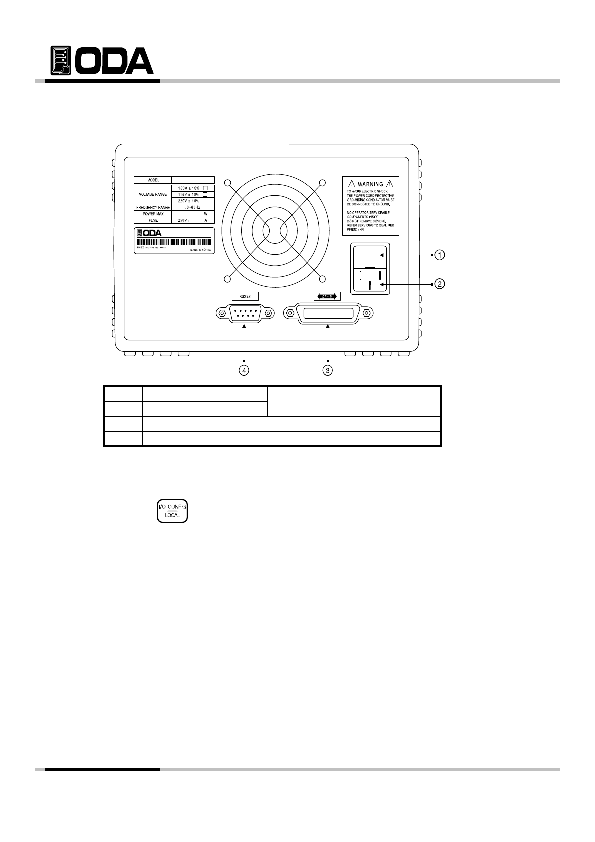
2-3. Rear Panel Composition
1
Fuse Holder
2
AC inlet
3 GPIB (IEEE-488) interface connector
RS-232C interface connector4
Power-line module
PC Interface Method
Press key on the front panel in other to set PC interface.
("Refer to chapter 3-3. I/O Config & LOCAL")
- 19 -
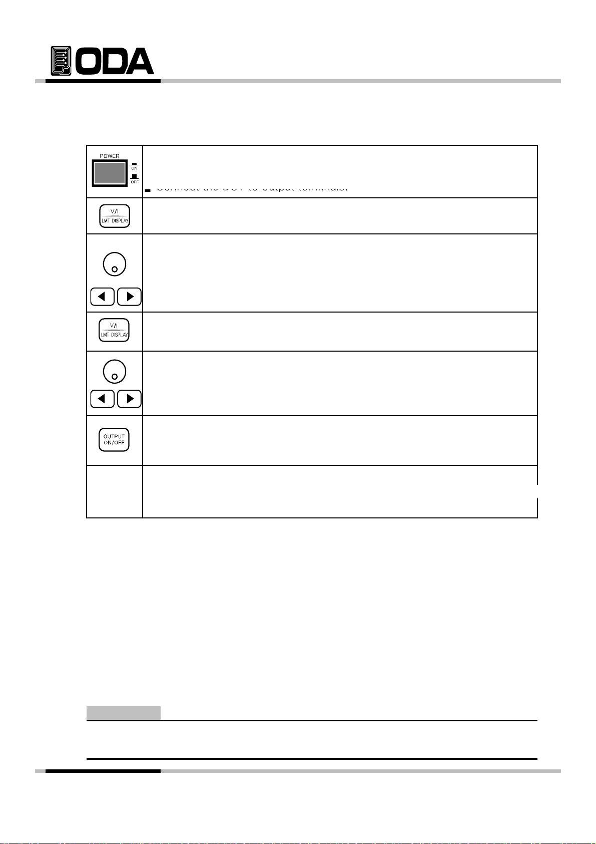
2-4. Output Check
d
prop
n
Press the
key and move the blinking cursor to voltage value
Set the current upto 5A by using encoder switch
clockwise
The following procedures check to ensure that the power supply develops its rated outputs an
erly responds to operation from the front panel. Forr complete performance and verificatio
refer to belows procedure.
Voltage Output Check
▌The following steps verify basic voltage functions with no load.
1. Turn on the power supply
2. The output is disabled (the OUTPUT OFF annunciator turns on)
3. In other to measure the voltage, connect the DVM to output terminals properly
4. Press the key in other to output the voltage.
5.
6. Press the key and select the voltage resolution what you want.
7. In other to increase or decrease, turn on the switch CW or CCW.
8. Compare between LCD display real voltage value and DVM annunciator.
.
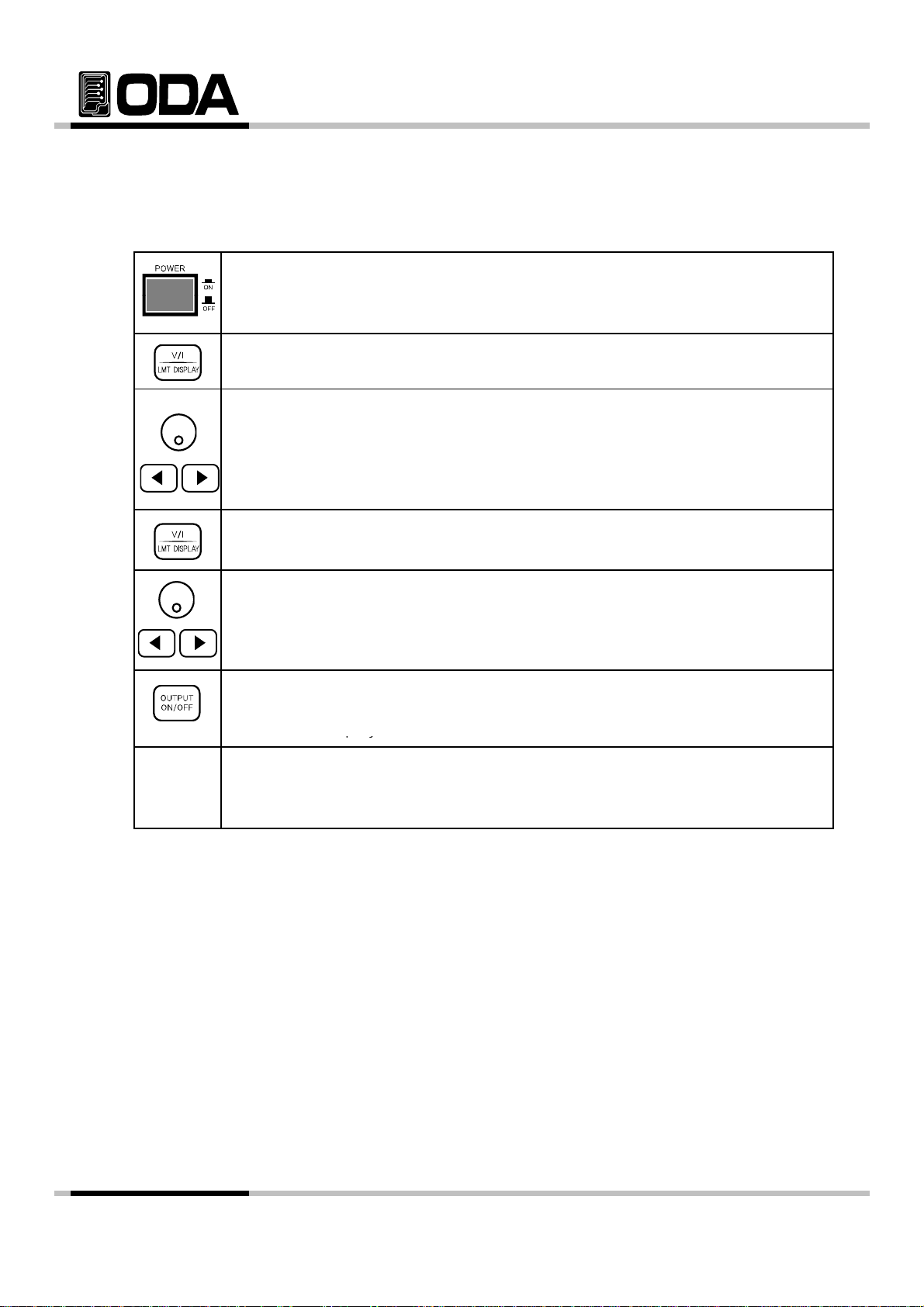
Current Output Check
▌The following steps check basic current functions with a short across the
power supply's output.
1. Turn on the power supply
2. The output is disabled (the OUTPUT OFF annunciator turns on)
3. Press the key in other to output the current.
4. Press the key and move the blinking cursor to current value.
5. Press the key and select the current resolution what you want.
6.
.
7. Press the key in other to output the current.
8. Compare between LCD display real current value and DAM annunciator.
- 20 -

3. Front-Panel Operating
6. I/O Config & LOCAL
So far you have learned how to install your power supply and perform initial operation.
During the initial operation, you were briefly introduced to operating from the front
panel as you learned how to check basic voltage and current functions. This chapter
will describe in detail the use of these front panel keys and show how they are used to
accomplish power supply operation.
Overview
1. Constant Voltage (CV)
Explanation about constant voltage output mode operation.
2. Constant Current (CC)
Explanation about constant current output mode operation.
3. Remote Voltage Sensing
Explanation about load's voltage sensing.
4. Programming Over Voltage Protection(OVP)
Explanation about over voltage protection.
5. Programming Over Current Protection(OCP)
Explanation about over current protection.
Explanation about remote interface setting and recovering to local mode.
7. KEY LOCK
Explanation about Front panel's locking function.
8. STORE / CALIBRATE
Explanation about User memory store.
9. RECALL / FACTORY
Explanation about how to use & apply the stored 『user memory』store.
10. OUTPUT ON/OFF
Explanation about the output disable or enable.
11. V/I 및 LMT DISPLAY
Explanation about voltage/current select or limit display.
12. CYCLING MODE
Explanation about Cycling mode.
13. ERROR
- 21 -
3-1. Constant Voltage Operating(CV)
▌
▌Connect the DUT to output terminals.
play
▌Pl
OUTPut[:STATe] {OFF|ON|0|1}
To set up the power supply for constant voltage (CV) operation, proceed as follows.
▌Turn ON the power supply
After turned on, check the power supply displays "**OUTPUT OFF**" .
Connect the DUT to output terminals.
▌In other to set the limit value, press the LMT key.
▌Adjust the knob & resolution button for the desired voltage limit.
▌Move the cursor to current.(Press the V/I Key once more)
▌Adjust the knob & resolution button for the desired current limit.
▌Enable the output.(Press the output ON/OFF key.)
After about 2.5 seconds later, power supply changes to readback display
from limit dis
ease check CV lamp is on, CC lamp is off.
If it is on and off opposite, check the load giving enough current, and raise
current limit value.
≫ Related Remote Interface Command
[SOURce:]VOLTage{<voltage>|UP|DOWN}
[SOURce:]CURRent{<current>|UP|DOWN}
:
Refer: OUTPUT OFF Block output
VOLT 10 Set voltage 10V
CURR 5 Set current 5A
OUTPUT ON Output Voltage & Current
.
Note
1. Select scale of increasing or decreasing voltage & current using cursor key.
2. ReadBack Display? It refers to displaying voltage & current 's output.
- 22 -
3-2. Constant Current Operating(CC)
After turned on, check the power supply displays
OUTPUT OFF
play
py
[SOURce:]CURRent{<
t>|UP|DOWN}
To set up the power supply for constant current (CC) operation, proceed as follows.
▌Turn on the power supply
"**
▌Connect the DUT to output terminals
▌In other to set the limit value, press the LMT Display key.
▌Adjust the knob & resolution button for the desired voltage limit.
▌Move the cursor to current.(Press the V/I Key once more)
▌Adjust the knob & resolution button for the desired current limit.
**"
.
≫ Related Remote Interface Command
[SOURce:]VOLTage{<voltage>|UP|DOWN}
OUTPut[:STATe] {OFF|ON|0|1}
Application :
▌Enable the output.(Press the output ON/OFF Key.
After about 2.5 seconds later, power supply changes to readback display
from limit dis
▌Check the CC annunciator is lit
If the CC annunciator turn off of twincle, choose a higher voltage limit.
curren
OUTPUT OFF Block output
VOLT 10 Setting voltage 10V
CURR 5 Setting current 5A
OUTPUT ON Voltage & Current OUTPUT ON
.
- 23 -

3-3. Remote Voltage Sensing
o
a
a
p
y
and power supply will be unregulated mode. Also, when each load leadline rise more than 1
When a electric load is connected from power supply's output terminal, voltage regulation will
from output terminal. Therefore, to supply accurate power to load, Remote Voltage Sensing
(V-Sensing) can be used. Please read below to use V-sensing correctly.
CV Regulation
Specification's voltage Load Regulation attribute.
While using V-Sensing, because of the change from current, 5mV should be added to this
between+S Point and +output terminal. Because, sensing lead line is power supply's feedb
It will stable when the resist value is below 0.5Ω.
Output Rating
Please read below about specification's output voltage & current.
When you use V-Sensing, the load leadline's voltage drop point will be added to it's load.
Therefore if you
the instrument will be unregulated not related to maximum voltage.
rint out more than maximum voltage, V-sensing mode will not guarantee
Note
What is UnRegulated mode? Disabled power supply's CC and CV
Output Noise
Noise from power supply's output can lead to a serious problem in Load Regulation.
Please follow the steps below :
▌twist sensing leadlines togeter to decrease noise from outside.
▌connect in a straight line with sensing leadline, when it's near load leadline.
▌cover sensing leadline when it's disclosed.
▌Noise cover equipment should be connected to GND in the closest location.
- 24 -
 Loading...