

Page 1

www.odacore.com
Programmable DC Power Supply
OPE-QI Series
User Manual
Manual Part NO. 018OPE-QI-2.0
Page 2

Legal Notices
© ODA Technologies.,Co.Ltd 2004
No part of this document may be photocopied, reproduced, or translated to another language without
the prior another language without the prior agreement and written consent of ODA agreement and
written consent of ODA Technologies.,Co.Ltd. as governed by Korea and international copyright laws.
Warranty Certification
The material contained in this document is provided “as is,” and is subject to being changed, without
notice, in future editions. Further, to the maximum extent permitted by applicable law, ODA disclaims
all warranties, either express or implied, with regard to this manual and any information contained
herein, including but not limited to the implied warranties of merchantability and fitness for a particular
purpose. ODA shall not be liable for errors or for incidental or be liable for errors or for incidental or
consequential damages in connection with the furnishing, use, or performance of this document or of
any information contained herein. Should ODA and the user have a separate written agreement with
warranty terms covering the material in this document that conflict with these terms, the warranty terms
in the separate agreement shall control.
Assistance
This product comes with the standard product warranty. Warranty options, extended support contacts,
product maintenance agreements and customer assistance agreements are also available.
Contact your nearest ODA Technologies. Sales and Service office for further information on
ODA Technologies. full line of Support Programs. Refer to below information.
www.odacore.com
oda@odacore.com
82-2-1800-8644
Waste Electrical and Electronic Equipment
The affixed product label (see right) indicates that you must not discard
this electrical/electronic product in domestic household waste. Do not
dispose in domestic household waste. To return unwanted products,
contact our local ODA distributors, or call us for more information.
Manual Editions
Manual Part Number: 018OPE-QI-2.0 Edition 2, February, 2018 Printed in ROK
Reprints of this manual containing minor corrections and updates may have the same printing date.
Revised editions are identified by a new printing date.
Page 3

Safety Notices
p
d
p
y
The following general safety precautions must be observed during all phases of operation of this
instrument. Failure to comply with these precautions or with specific warnings or instructions elsewhere
in this manual violates safety standards of design, manufacture, and intended use of the instrument.
ODA Technologies assumes no liability for the customer's failure to comply with these requirements.
eneral Do Not Modify the Instrument
G
Do not use this product in any manner not
specified by the manufacturer. The protective
features of this product may be impaired if it is
used in a manner not specified in the operation
instructions.
Do not install substitute parts or perform any u
nauthorized modification to the product. Return
the product to an ODA Sales and Service Office
for service and repair to ensure that safety
features are maintained.
round the Instrument
G
This product is a Safety Class 1 instrument
(provided with a protective earth terminal).
To minimize shock hazard, the instrument unintended o
chassis and cover must be connected to an qualified service personnel.
electrical ground. The instrument must be
connected to the ac power mains through
a grounded power cable, with the ground
wire firmly connected to an electrical ground
(safety ground) at the power outlet. Any attention to an operating procedure, practice, or
interruption of the protective (grounding) the like that, if not correctly
conductor or disconnection of the protective to, could result in damage to the product or loss
earth terminal will cause a potential shock
hazard that could result in personal injury. C
Before Applying Power are fully understood and met.
Verify that all safety precautions are taken.
Make all connections to the unit before W
applying power. Note the instrument's A WARNING notice denotes a hazard. It calls
external markings described under attention to an operating procedure, practice,
Fuses death. Do not proceed beyond a WARNING
The instrument contains an internal fuse, which notice until the indicated conditions are fully
is not customer accessible.
n Case of Damage
I
Instruments that appear damaged or defective
should be made inoperative and secured against
eration until they can be repaired b
AUTION
C
AUTION notice denotes a hazard. It calls
A C
erformed or adhere
of important data. Do not proceed beyond a
AUTION notice until the indicated conditions
ARNING
rofrep yltcerroc ton fi ,taht ekil eht ro "slobmyS ytefaS" med or
adhered to, could result in personal injury or
understood and met.
D
o Not Operate in an Explosive Atmosphere
Do not operate the instrument in the presence
of flammable gases or fumes.
D
o Not Remove the Instrument Cover
Only qualified, service-trained personnel who
are aware of the hazards involved should
remove instrument covers. Always disconnect
the power cable and any external circuits before
removing the instrument cover.
Page 4

Safety Symbol
Direct current
Both direct and alternating current Three phase alternating current
Earth (ground) terminal
Frame or chassis terminal
Neutral conductor on
permanently installed
equipment
Alternating current
Protective earth ground terminal.
Terminal is at earth potential.
Line conductor on
permanently installed equipment.
Standby supply. Unit is not
completely disconnected
from ac mains when switch
is off
Out position of a bi-stable
push switch
Caution, hot surface
ylppus ffO ylppus nO
In position of a bi-stable push
switch
Caution, risk of electric shock
Caution, refer to accompanying
documents
Page 5

CONTENTS
1. General Information
------------------------------------------------------------------------------
4
1-1. Feature
------------------------------------------------------------------------------------------------------
4
General Feature
Remote Interface
Calibration
1-2. Accessories & Options
------------------------------------------------------------------------------
5
Accessories
Options
Homepage and Reference(www.odacore.com)
1-3. Check
----------------------------------------------------------------------------------------------------------
6
Instrument Check
Electrical Check
1-4. Operation Conditions
----------------------------------------------------------------------------------------------------------
6
1-5. Check Before Power On
----------------------------------------------------------------------------------------------------------
7
Output Terminal Check
Power Cord Check
Input Power Line Check
1-6. Check After Power On
----------------------------------------------------------------------------------------------------------
9
Display Procedure on the LCD
Default Setting Values
1-7. Installation
----------------------------------------------------------------------------------------------------------
10
Cooling
Bench Operation
Rack Mounting
2. Front Panel, Rear Panel Composition & Function
----------------------------------------------------------------------------------------------------------
12
2-1. Front-Panel
----------------------------------------------------------------------------------------------------------
12
2-2. Front-Panel Setting
----------------------------------------------------------------------------------------------------------
20
2-3. Rear Panel Composition
----------------------------------------------------------------------------------------------------------
21
2-4. Output Check
----------------------------------------------------------------------------------------------------------
22
Voltage Output Check
Current Output Check
- 2 -
Page 6

3. Front-Panel Operating
---------------------------------------------------------------------------------------------
23
Overview
3-1. Constant Voltage Operation (CV)
------------------------------------------------------------
24
3-2. Constant Current Operating (CC)
------------------------------------------------------------
25
3-3. I/O & LOCAL
---------------------------------------------------------------------------------------------
26
RS232C Setting
RS485 Setting (Option)
RS232C & RS485 Communication Specification
RS232C Connection Drawing
RS485 Connection Drawing
3-4. STORE
30
3-5. RECALL
30
3-6. OUTPUT ON/OFF
--------------------------------------------------------------------------------------
31
3-7. V/I & LMT DISPLAY
31
3-8. P1/P2 Select & TRACKING
--------------------------------------------------------------------
32
3-9. Remote Voltage Sensing (option)
--------------------------------------------------------------------
34
3-10. Last Memory (option)
-------------------------------------------------------------------------
34
4. SCPI Command
-------------------------------------------------------------------------------------------
35
4-1. Commands Syntax
---------------------------------------------------------------------------------------------
35
4-2. Commands
----------------------------------------------------------------------------------------------------
35
4-3. Channel Select Command
-----------------------------------------------------------------------------
36
4-4. Output Voltage / Current Setting & Operating Command
-----------------
37
4-5. Protection Command (option)
----------------------------------------------------------------------------------
37
4-6. Measure Command
----------------------------------------------------------------------------------
38
4-7. System Command
-----------------------------------------------------------------------------------
38
5. Caution
--------------------------------------------------------------------------------------------------------
40
---------------------------------------------------------------------------------
- 3 -
------------------------------------------------------------------------------------------------------
-----------------------------------------------------------------------------------------------------
Page 7

1. General Information
1-1. Feature
ODA Technologies' OPE-Series Single & Dual Output products are high performance programmable DC Power
supply with RS232C or RS485 interface based on SCPI (Standard Commands for programmable Instruments)
protocol and the combination of bench-top and system features in these power supplies provides versatile
solutions for your design and test requirements in the industrial fields, R&D institute center and education fields.
General Feature
▌Easy-to-use knob control settings
▌2-Line * 16Char LCD Display(Ch1 ,Ch2 Voltage/Current Display)
▌Output voltage & current On/OFF
▌Alarm beep when events occur
▌Excellent Load Regulation & Line Regulation
▌Save & Recall 5 Operating State
▌Size(2U * 19inch Half-Rack , 19inch Rack Compatibility)
▌Safety power down mode when detecting system malfunction
Remote Interface
▌RS232C or RS485 Interface
▌SCPI(Standard Commands for Programmable Instruments) Compatibility
▌High speed setting & measument
▌Abundant Commands
▌I/O setup easily done from front-panel
▌Insulation from instrument and floating logic embodiment
▌Built-in SCPI Programming error check function
Calibration
▌Software Calibration, no internal adjustments required
▌Easy calibration by using PC interface
- 4 -
Page 8

1-2. Accessories and Options
Accessories
▌1 AC Input Power Cord
▌Output 1 (+), (-) Terminal. (Part number : OE-LW-BCW-2.0)
▌User's Manual 1 piece.
Option
▌RS485 Module
▌RS485 to RS232 Convertor
▌RS232C Cross Cable 1M, 2M, 4M, 10M
▌100V, 110V, 115V, 230V ± 10% , 50~60Hz AC Power Input
▌Rear Output Terminal
▌Rack mount Support (Bracket and Shelf)
Homepage and Reference (www.odacore.com)
▌Windows application demo version included manual
▌National instrument company's LabVIEW VI supply
▌Technical information for Power Supply included.
- 5 -
Page 9

1-3. Check
When you receive your power supply, inspect it for any obvious damage that may have
occurred during shipment. If any damage is found, notify the carrier and the nearest ODA
Sales Office immediately. Warranty information is shown in the front of this manual. Keep
the original packing materials in case the power supply has to be returned to ODA
Technologies in the future. If you return the power supply for service, attach a tag
identifying the owner and model number. Also include a brief description of the problem.
Mechanical Check
▌Check the broken key, encoder switch, power switch.
▌Check the broken output terminals.
▌Check the panel surfaces are free of dents and scratches.
▌Check the cabinet is free of scratches.
▌Check the LCD display is not scratched or cracked.
Electrical Check
▌When turning on the power, it shows instrument model and ODA website at first.
▌Check the model Number is matched with displayed model number.
▌After it shows "**OUTPUT OFF**" message, verifies to a high level of confidence
that the power supply is operating in accordance with its specifications.
Service Center : 82-70-5032-2926
Home page : www.odacore.com
1-4. Operating Conditions
The instrument is designed for following environmental conditions in order to use optimized
condition.
▌Environmental Temperature : 0 ∼ 40℃
▌Relative Humidity : ≤ 80% RH
▌Operating altitude : ≤ 2000m
▌No vibration
▌Avoid the electric magnetic field
- 6 -
Note
Page 10
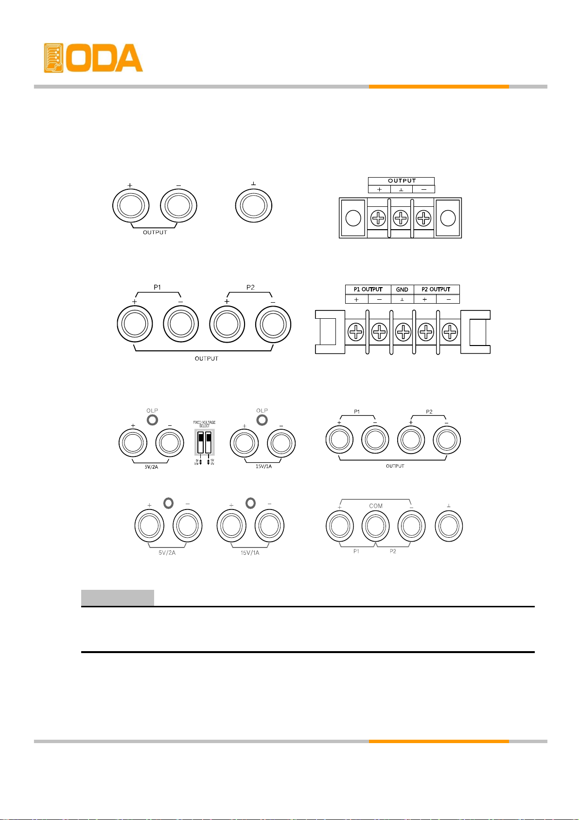
1-5. Check Before Power On
Output Terminal Check
▌Check the variable output and fixed output terminals.
Front Output Rear Output
< figure 1-1> OPE-S Series
Front Output Rear Output
< figure 1-2> OPE-DI Series
OPE-QI Series
OPE-Q Series
< figure 1-3> OPE-QI , Q Series
Floating the power supply output more than ±60 Vdc from the chassis presents an
electric shock hazard to the operator.
Power Cord Check
▌Your power supply is equipped with a 3-wire grounding type power cord; the third
conductor being the ground. The power supply is grounded only when the power line cord is plugged into an appropriate receptable. Do not operate your power
supply without adequate cabinet ground connection.
WARNING
- 7 -
Page 11
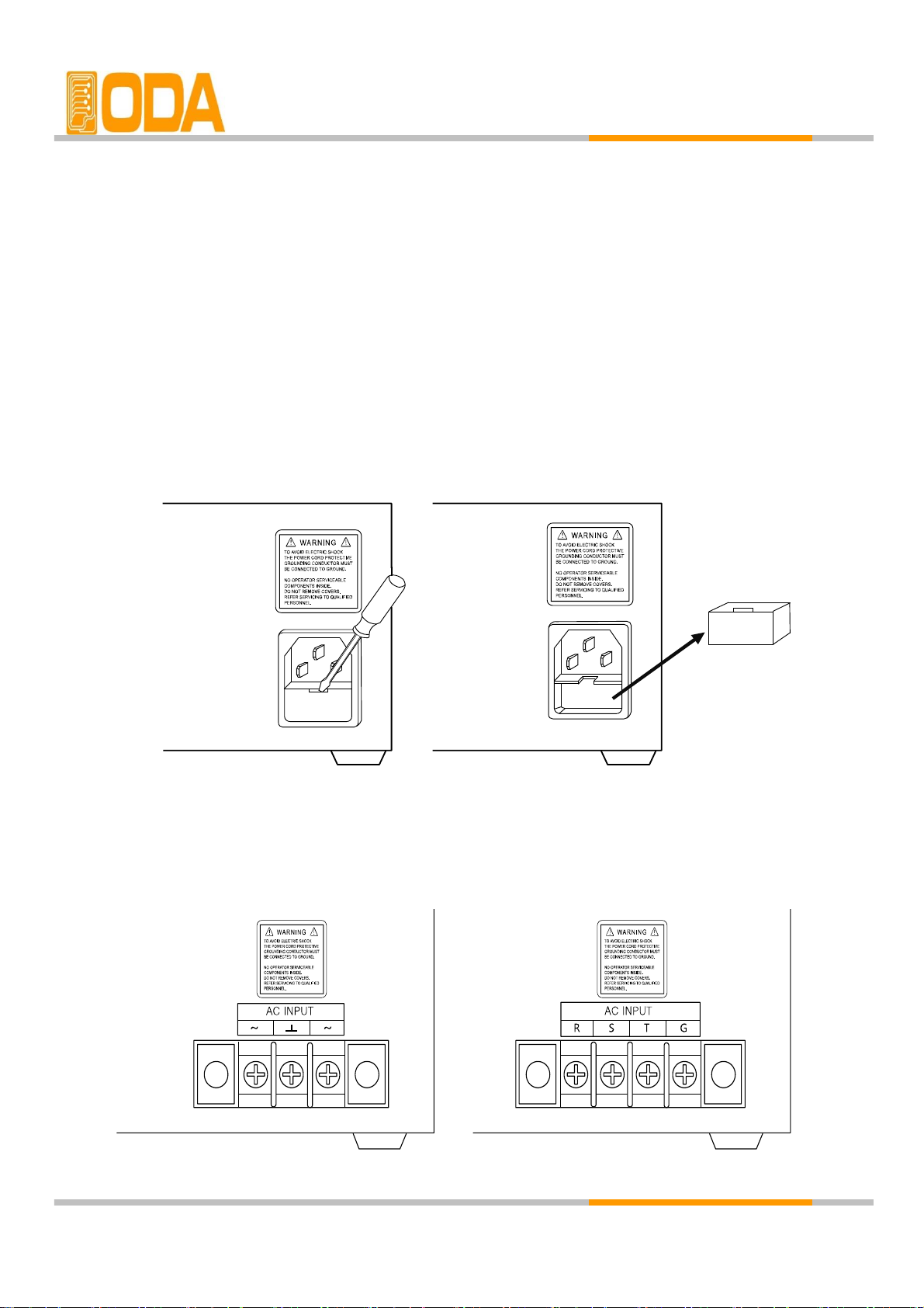
Input Power Line Check
▌You can operate your power supply from a nominal 198-242 V single phase AC
power source at 47 to 63 Hz. AC 100V, 110V, 115V, 230V input power is optional.
Refer to chapter "1-2, Accessories & Options"
▌In order to prevent the instrument severe damage from overload, fuse is installed
in inlet case. If the fuse is also repeatedly when power turns on, check the
input power line or broken breaker and then call to nearest ODA Technologies A / S Center
Input power connection is following.
< figure 1-3> Output capacity 90W ~ 300W or 400W ~ 600W Input Power
< figure 1-4> Output Capacity Over 400W Customized Input Power
- 8 -
Page 12

1-6. Check After Power On
When turning on the power switch, the front-panel display will light up briefly while the
instrument performs its power-on default value setting. And also keep the ex-remote
interface setting mode, voltage value is zero and current value is max value.
Display Procedure on the LCD
▌Display "OPE-303S V1.0" and website address
Visit ODA Technologies website. Get the manuals, windows application software demo, and upgrade
information & technical support.
▌Display "**OUTPUT OFF**"
▌By using front panel key and encoder switch, set the voltage/current and functions.
Default Setting Values
▌Output Voltage : 0V ▌Cursor location : Default voltage.
▌Output Current : Limit setting max value Voltage : 1V Unit
▌Output Select : Voltage Current : 0.1A Unit
▌Remote Interface : ex-remote interface setting mode
▌After standby mode : Display "**OUTPUT OFF**"
The RS232C is attached in the instrument when the power supply is shipped from the
factory for remote interface configuration and baud rate is set 9600bps at first time.
In case of choosing RS 485 interface, address no. is 05 when this is shipped from the factory.
For your safety, Setting Voltage and Current will not be set up after turn-on.
After power on, power supply will be in "**OUTPUT OFF**" Mode.
Note1
Note2
- 9 -
Page 13
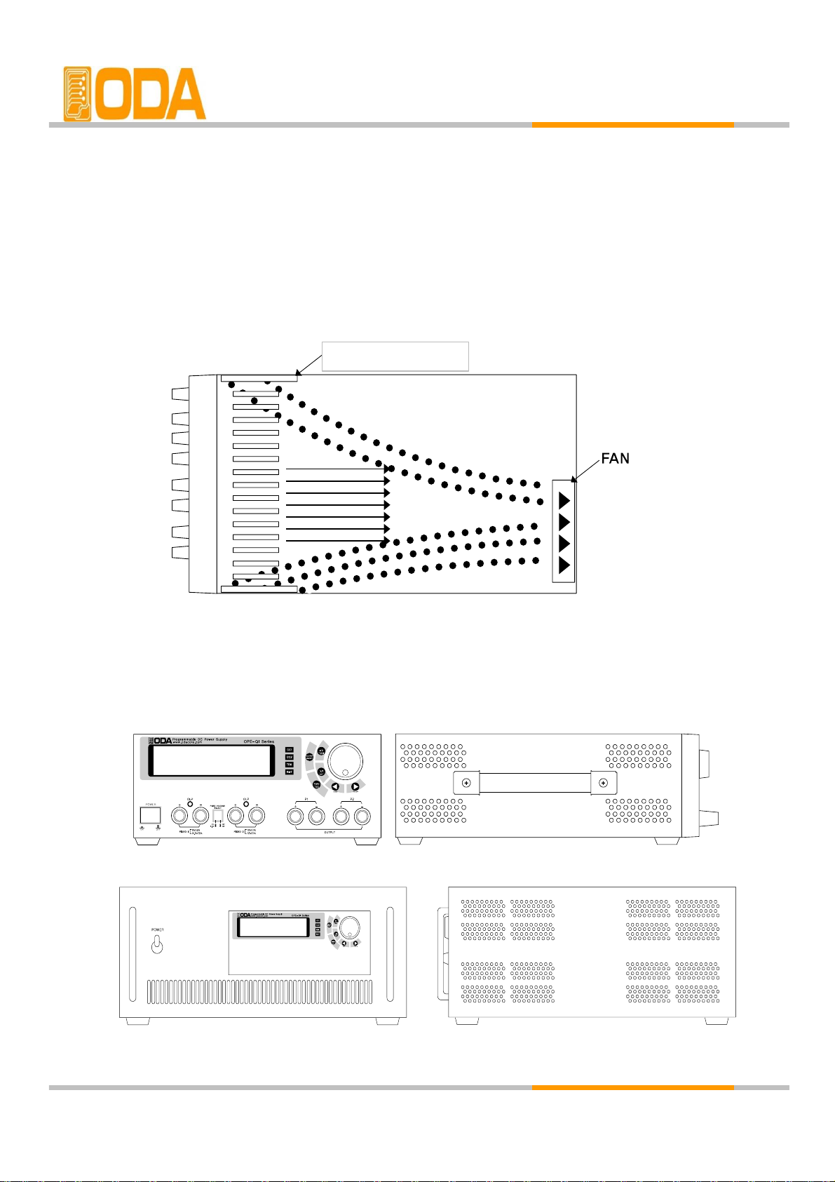
1-7. Installation
Cooling
▌The power supply can operate without loss of performance within the
temperature range of 0℃ to 40℃, and with derated output current from
40℃ to 55℃. A fan cools the power supply by drawing air through the rear
panel and exhausting it out the sides. Using an ODA rack mount will not
impede the flow of air.
< figure 1-6 Bottom view>
Bench Operation
▌Your power supply must be installed in a location that allows sufficient space
at the sides and rear of the power supply for adequate air circulation.
< figure 1-7 > 2U * 19inch Half
< figure 1-8> 19inch
- 10 -
ventilation opening
Page 14
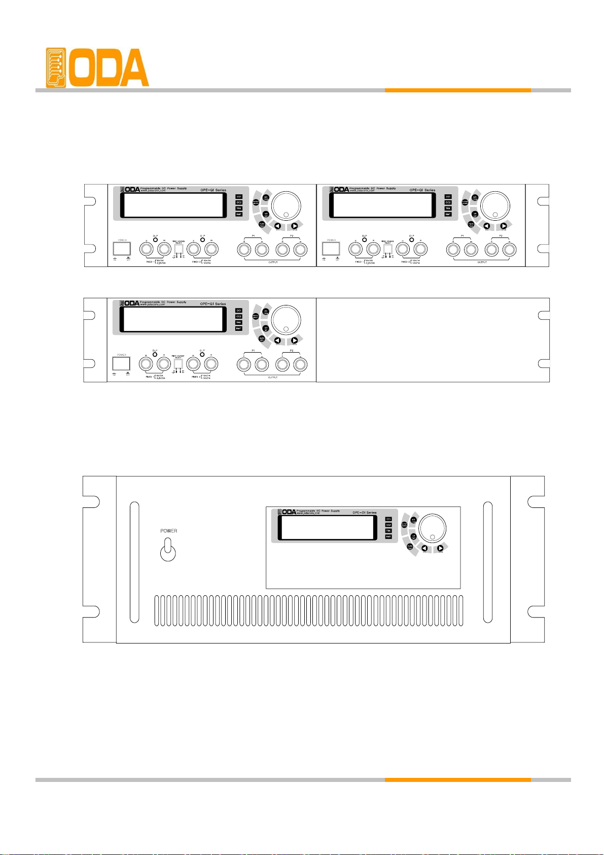
Rack Mounting
▌Power supply is designed for 2U * 10 inch Rack ( Half Size )
remove the rubber on the bottom and put the rack bracket
< figure 1-9 > 2U * 19inch Half Setting
▌This is designed for 19 inch size rack. Before installment,
remove the rubber on the bottom and put the rack bracket
< figure 1-10 >19inch fixed product
- 11 -
Page 15

2. Front Panel, Rear Panel Composition & Function
2-1. Front-Panel
OPE-S Series
1 8
2 9
3 10
4 11
5 12
6 13
7
I/O or LOCAL Key
+ Output Terminal
Output ON/OFF Key
- Output Terminal
Earth GND Terminal
Volt/Curr Cursor or menu change Key
LCD (Volt/Curr and Message Display Module)
Constant Current mode indicate lamp
Main Power ON/OFF Switch
Encoder S/W for changing Volt/Curr
Remote Interface mode indicate lamp
- 12 -
Volt/Curr Cursor or menu change Key
Volt/Curr select or Limit Display Key
Page 16

1. LCD ( Voltage, current and Message Display display window)
Voltage/current and, all kinds menu/message display
2. Voltage/current Changing Encoder Switch
Increases or decrease the value of the blinking digit by turning clockwise or counter clockwise.
3. I/O or LOCAL Key
Configures the power supply for remote interfaces. Set baud rate of RS232C. If remote
interface is RS485, it can be used for setting baud rate & address. Also under Remote interface
situation, in order to recover bench top using, this key operate to local from remote.
4. Output ON/OFF
Enables or disables the power supply output. This key toggles between on and off.
5. Voltage/Current select or Limit Display Key
Shows voltage and current limit values on the display and allows knob adjustment for
setting limit values.
6 . Voltage/Current Cursor or menu changing Key
Move the blinking digit to the left.
In menu mode, it can change menu tree.
Under the "**OUTPUT OFF**" mode, this key work on store key.
7. Voltage/Current Cursor or menu changing Key
Move the blinking digit to the right.
In menu mode, it can change menu tree.
Under the "**OUTPUT OFF**" mode, this key work on recall key.
8. Constant Current mode indicate lamp
The power supply is in constant current mode.
If it turns off, the power supply is in constant voltage mode.
9. Remote Interface mode indicate lamp
Power supply is in remote interface mode.(PC Interface or Remote Interface)
All key is locked except "I/O & Local" key.
10. + Output Terminal
This is + Output terminal. This outputs + voltage and current.
11. - Output Terminal
This is - Output terminal. This outputs - voltage and current.
12. Earth GND Terminal
GND terminal, it is able to connect to earth terminal of the DUT
13. Main Power ON/OFF Switch.
The power supply is turned on or off by this switch. It is adopted by following power supply's
capacity.
- 13 -
Page 17

OPE- DI Series
OPE- QI Series
1
LCD (Volt/Curr and Message Display Module)
14
2
Encoder S/W for changing Volt/Curr
15
P2 Variable Channel + Output Terminal
3
I/O or LOCAL Key
16
P2 Variable Channel - Output Terminal
4
Output ON/OFF Key
17
Main Power ON/OFF Switch
5
Volt/Curr select Limit Display Key
6
Output channel select or Tracking Key
18
5V/2A & 3.3V/2A(Fixed 1) + Output Terminal
7
Volt/Curr Cursor or menu change Key
19
5V/2A & 3.3V/2A(Fixed 1) - Output Terminal
8
Volt/Curr Cursor or Menu Change Key
20
15V/1A & 12V/2A(Fixed 2) + Output Terminal
9
P1 Constant Current Mode Indicate Lamp
21
15V/1A & 12V/2A(Fixed 2) - Output Terminal
10
P2 Constant Current Mode Indicate Lamp
22
Fixed 1 Over Load Protection Lamp
11
P1, P2 Channel Tracking Mode Indicate Lamp
23
Fixed 2 Over Load Protection Lamp
12 24
13
Fixed 1 & Fixed 2 Voltage Select Switch
P1 Variable Channel - Output Terminal
P1 Variable Channel + Output Terminal
- 14 -
Remote Interface Mode Indicate Lampe
OPE- QI Series
Page 18

1. LCD (Voltage, current and message display window)
Voltage/current and, all kinds menu/message display
2. Voltage/current Changing Encoder Switch.
Increase or decreases the value of the blinking digit by turning clockwise or counter clockwise.
3. I/O or LOCAL Key
Configures the power supply for remote interfaces. Set baud rates of RS232C. If remote
interface is RS485, it can be used for setting baud rate & address. Also under Remote Interface
situation, in order to recover bench top using, this key operate to local from remote.
4. Output ON/OFF
Enables or disables the power supply output. This key toggles between on and off.
5. Voltage/Current select or Limit Display Key
Shows voltage and current limit values on the display and allows knob adjustment for setting
limit values.
6. Output channel select or tracking key
Channel select key between P1 & P2. When pressing once, it changes to P1 from P2 or
vice versa. When Pressing this key during 1 second more, it changes to tracking mode.
7. Voltage/Current Cursor or menu changing Key
Move the blinking digit to the left.
In menu mode, it can change menu tree.
Under the "**OUTPUT OFF**" mode, this key work on store key.
8. Voltage/Current Cursor or menu changing Key
Move the blinking digit to the right.
In menu mode, it can change menu tree.
Under the "**OUTPUT OFF**" mode, this key work on recall key.
9. P1 Constant Current mode indicate lamp
The power supply is in constant current mode.
If it turns off, the power supply is in constant current mode.
10. P2 Constant Current mode indicate lamp
The power supply is in constant current mode.
If it turns off, the power supply is in constant voltage mode.
11. P1, P2 Tracking mode indicate lamp
When the power supply is in tracking mode of P1 & P2 Channel, it turns on.
12. Remote Interface mode indicate lamp
Power supply is in remote interface mode. (PC Interface or Remote Interface)
All key is locked except "I/O & Local" key.
- 15 -
Page 19

13. P1 Variable + Output Terminal
14. P1 Variable - Output Terminal
15. P2 Variable + Output Terminal
16. P2 Variable - Output Terminal
17. Main Power ON/OFF Switch
18. 5V2A & 3.3V/2A (Fixed) + Output Terminal
19. 5V2A & 3.3V/2A (Fixed) - Output Terminal
20. 15V1A & 12V/1A (Fixed) + Output Terminal
21. 15V1A & 12V/1A (Fixed) - Output Terminal
22. Fixed 1 Over Load Protection Lamp
It turns on when fixed 1 channel is under the OLP state.
23. Fixed 2 Over Load Protection Lamp
It turns on when fixed channel is under the OLP state.
24. Fixed 1, Fixed2 Voltage Select Switch.
You can select Fixed 1 (5V/2A, 3.3V/2A), Fixed 2(15V/1A, 12V/1A).
- 16 -
Page 20

OPE- Q Series
1 13
2 14
P1 & P2 Output COM Terminal
3 15
P1 - Output Terminal (Negative Output)
4 16
Variable Cannel P2 - Output Terminal
5 17
Main Power ON/OFF Switch
6 18
Fixed 1(5V/2A) + Output Terminal
7 19
Fixed 1(5V/2A) - Output Terminal
8 20
9 21
10 22
Fixed 1 Over Load Protection Lamp
11 23
Fixed 2 Over Load Protection Lamp
12
Volt/Curr Cursor or menu change Key
Fixed 2(15V/1A) - Output Terminal
P1 Constant Current mode indicate Lamp
P2 Constant Current mode indicate Lamp
P1, P2 channel tracking mode indicate Lamp
Encoder S/W for changing Volt/Curr
P1 + Output terminal (Positive Output)
Fixed 2(15V/1A) + Output Terminal
- 17 -
Output ON/OFF Key
Volt/Curr select or limit display Key
Output channel select or tracking Key
Remote Interface mode indicate Lamp
Volt/Curr Cursor or menu change Key
I/O or Local Key
LCD(Volt/Curr and Message Display Module)
Page 21

1. LCD (Voltage, current and message display window)
Voltage/current and, all kinds menu/message display
2. Voltage/current Changing Encoder Switch
Increase or decrease the value of the blinking digit by turning clockwise or counter clockwise.
3. I/O or LOCAL Key
Configures the power supply for remote interfaces. Set baud rate of RS232C. If remote
interface is RS485, it can be used for setting baud rate & address. Also under Remote Interface
Situation, in order to recover bench top using, this key operate to local from remote.
4. Output ON/OFF
Enables or disables the power supply output. This key toggles between on and off.
5. Voltage/Current select or Limit Display Key
Shows voltage and current limit values on the display and allows knob adjustment for setting
limit values.
6. OUTPUT SELECT or Tracking Key
Channel select key between P1 & P2. When pressing once, it changes to P1 from P2 or
vice versa. When pressing this key during 1 second more, it changes to tracking mode.
7. Voltage/Current Cursor or menu changing Key
Move the blinking digit to the left. In menu mode, it can change menu tree.
Under the "**OUTPUT OFF**"mode, this key work on store key.
8. Voltage/Current Cursor or menu changing Key
Move the blinking digit to the right. In menu mode, it can change menu tree.
Under the "**OUTPUT OFF**"mode, this key work on recall key.
9. P1 Constant Current mode indicate Lamp
The power supply is in constant current mode.
If it turns off, the power supply is in constant voltage mode.
10. P2 Constant Current mode indicate Lamp
The power supply is in constant current mode.
If it turns off, the power supply is in constant voltage mode.
11. P1, P2 Tracking Mode Indicate Lamp
When the power supply is in tracking mode of P1 & P2 channel, it turns on
12. Remote Interface Mode Indicate Lamp
Power supply is in remote interface mode.(PC Interface or Remote Interface)
All key is locked except "I/O & Local" Key.
- 18 -
Page 22

13. P1 + COM Output terminal
14. P1 & P2 Output COM Terminal
15. P2 - COM Output Terminal
16. Earth GND Terminal
GND terminal, it is able to connect to earth terminal of the DUT.
17. Main Power ON/OFF Switch
The power supply is turned on or off by this switch. It is adopted by following power supply's
capacity.
18. Fixed 1(5V2A) + Output Terminal
19. Fixed 1(5V2A) - Output Terminal
20. Fixed 2(15V1A) + Output Terminal
21. Fixed 2(15V1A) - Output Terminal
22. Fixed 1 Over Load Protection Lamp
It turns on when fixed 1 channel is over the OLP state.
23. Fixed 2 Over Load Protection Lamp
It turns on when fixed 2 channel is over the OLP state.
- 19 -
Page 23

2-2. Front-Panel Setting
You can set the voltage and current limit values from the front panel using the following method.
1. Confirm the display of "OUTPUT OFF" on the LCD after turning on the power supply.
3. Press the key to show the limit values on the display.
<OPE-DI Series - checking the channel, press the key.
4. Press the key once time more to select between voltage and current.
5. In order to select the digit cursor about increase or decrease, press or
to move the state to desired resolution digit cursor.
6. In order to increase limit value, turn the encoder clockwise.
In order to decrease limit value, turn the encoder counter clockwise.
7. Confirm the change of setting value at LCD display.
8. Please press key to output the setting voltage and current.
When press key, disappear the message of "**OUTPUT OFF**" and then change to limit
display state, and cursor is blinking. At that time, if let the display time-out after 3 seconds,
"**OUTPUT OFF**" display at the LCD.
If it is under remote control, key and encoder switch on the front panel won't operate.
If turning to local mode from remote control, press key to change to local mode.
Note1
Note2
- 20 -
Page 24

2-3. Rear Panel Composition
Standard 2U * 19 inch Half
AC inlet
PC Interface Method
Press key on the front panel in order to set PC interface.
(Please refer to chapter3-6. I/O Config & LOCAL)
RS-232C interface connector
Power-line module
Fuse Holder
232
DC Output ( P1,P2 2 Output in DI-Series )
3
AC Input
Customized 19inch
1
RS-232C interface connector
- 21 -
1
Page 25

2-4. Output Check
The following procedures check to ensure that the power supply develops its rated
outputs and properly responds to operation form the front panel. For complete performance
and verification test, refer to belows procedure.
Voltage Output Check
▌The following steps verify basic voltage functions with no load.
1. Turn on the power supply.
2. The output is disabled (the OUTPUT OFF annunciator turns on)
3. In order to measure the voltage, connect the DVM to output terminals properly.
4. Press the key in order to output the voltage.
5. Press the key and move the blinking cursor to voltage value.
6. Press the key and select the voltage resolution what you want.
7. In order to increase or decrease, turn on the switch CW or CCW.
8.Compare between LCD display real voltage value and DVM annunciator.
9. If you use DI Series, Press Key and select P2 and repeat the 3~8 course to check.
Current Output Check
▌The following steps check basic current functions with a short across the
power supply's output.
1. Turn on the power supply
2. The output is disabled (the OUTPUT OFF annunciator turns on)
3. Press the key in order to output the voltage.
4. Press the key and move the blinking cursor to voltage value.
5. Press the key and select the voltage resolution what you want.
6. Set the voltage up to 5V by using encoder switch clockwise.
7. Press the key in order to output the voltage
8. Press the key and select the current resolution what you want
9. In order to measure current, connect the test leads to output terminals properly.
10. Press the key in order to output the current.
11. Press the key in order to output the current.
12. Compare between LCD display real current value and DAM annunciator.
13. If you use DI Series, Press Key and select P2 and repeat the 3~8 course to check.
- 22 -
Page 26

3. Front-Panel Operating
So far you have learned how to install your power supply and perform initial operation.
During the initial operation, you were briefly introduced to operating from the front
panel as you learned how to check basic voltage and current functions. This chapter
will describe in detail the use of these front panel keys and show how they are used to
accomplish power supply operation.
Overview
1. Constant Voltage Operation(CV)
Explain constant voltage output mode operation.
2. Constant Current Operation(CC)
Explain constant current output mode operation
3. I/O & LOCAL
Explain remote interface setting and recovering to local mode.
4. STORE
Explain 『user memory』 store.
5. RECALL
Explain how to use & apply the sorted 『user memory』 store.
6. OUTPUT ON/OFF
Explain the output disable or enable.
7. V/I & LMT DISPLAY
Explain voltage/current select or limit display.
- 23 -
Page 27

3-1. Constant Voltage Operating (CV)
To set put the power supply for constant voltage (CV) operation, proceed as follows.
▌Turn on the power supply.
After turned on, check the power supply displays "**OUTPUT OFF**"
▌Connect the DUT to output terminals.
▌In order to set the limit value, press the LMT Key.
Adjust the knob & resolution button for the desired voltage limit.
▌Move the cursor to current ( Press the V/I Key one more time.)
▌Enable the output. (Press the output ON/OFF key.)
After about 2.5 seconds later, power supply changes to read back display
from limit display.
▌Check the CC annunciator turn off.
If the CC annunciator is lit, choose a higher current limit.
≫ Related Remote Interface Command
VOLT <voltage>
CURR <current>
OUTP {OFF|ON}
Application:
OUTP OFF Disable the output
INST OUTP1
Select Channel P1 ( If 2CH , Select channel P1 or P2 )
VOLT 10 Set the voltage to 10V
CURR 5 Set the current to 5A
OUTP ON Enable the output
1. You can use the resolution selection keys (cursor key) to move the blinking digit to the right
or left when setting value.
2. Read back display meas the state of outputting of real voltage/ current display value.
Note
- 24 -
CC
Page 28

3-2. Constant Current Operating (CC)
To set up the power supply for constant current (CC) operation, proceed as follows.
▌Turn on the power supply.
After turned on, check the power supply displays "**OUTPUT OFF**"
▌Connect the DUT to output terminals.
▌In order to set the limit value, press the LMT Key.
▌Adjust the knob & resolution button for the desired voltage limit.
▌Move the cursor to current. ( Press the V?I Key one more time.)
▌Adjust the knob & resolution button for the desired current limit.
▌Enable the output. (Press the output ON/OFF key.)
After about 2.5 seconds later, power supply changes to read back display
from limit display.
▌Check the CC annunciator is lit.
If the CC annunciator turn off or twinkle, choose a higher voltage limit.
≫ Related Remote Interface Command
VOLT <voltage>
CURR <current>
OUTP {OFF|ON}
Application:
OUTP OFF Disable the output
INST OUTP1
Select Channel P1 ( If 2CH , Select channel P1 or P2 )
VOLT 10 Set the voltage to 10V
CURR 5 Set the current to 5A
OUTP ON Enable the output
- 25 -
CC
Page 29

3-3. I/O & LOCAL
To configure the power supply for the RS-232C and RS-485 interface, proceed as follows.
RS 232C interface is standard, in case of RS-485, it is optional and remove the RS232C module.
If interface is RS-485 when it is shipped, Address default is no.05.
Baud rate default is 9600bps and setting of RS-232C & RS-485 is able to set on front panel.
▌The RS-232C baud rate and parity selections are stored in non-volatile memory,
and does not change when power has been off or after a remote interface reset.
▌I remote interface works, the lamp of RMT on front panel lits and power supply is
remotely controlled preferentially.
▌If you want to control power supply on local mode, at first finish remote interface
and then press the key. Lamp of "RMT" turn off and you can control.
RS232C Setting
RS232C setting procedure.
▌Turn on the power supply.
After turned on, check the power supply displays "**OUTPUT OFF**"
▌Press "I/O"key in order to set RS-232C interface.
LCD Display
1 raw 2 raw
▌When press the left & right cursor key, you can change the Baud-Rate.
▌Baud rate consists of 1200bps, 2400bps, 9600bps, 19200bps
and it must be matched between PC interface Baud rate..
For examples, in order to select 19200bps, press right cursor key.
LCD Display
1 raw 2 raw
▌In order to finish the I/O setting, press the "I/O"key.
LCD Display
1 raw 2 raw
Bps is the initial of Bit Per Second, data transmission unit of 1 bit per one second.
DONE
Note
- 26 -
BAUD-RATE
DONE
BAUD-RATE
DONE
BAUD-RATE
Page 30

RS485 Setting
RS485 setting procedure
▌Turn on the power supply
After turned on, check the power supply displays "**OUTPUT OFF**".
▌Press "I/O"key in order to set RS-485 interface.
LCD Display
1 raw
ADDRESS> 0x05
2 raw
SPEED> 9600bps
▌In order to change the address, turn the encoder switch CW or CCW.
▌HEX value Displays variable range of address in from 00 to FF(total 256).
For examples, turn right one click in order to select address no.06
LCD Display
1 raw ADDRESS> 0x06 2 raw SPEED> 9600bps
▌In order to change speed(Baud-Rate), press the right & left cursor key.
▌Baud rate consists of 1200bps, 2400bps, 9600bps, 19200bps
and it must be matched between PC interface Baud rate.
For example, in order to select 19200bps, press right cursor key.
LCD Display
1 raw ADDRESS> 0x06 2 raw SPEED> 19200bps
▌In order to finish the I/O setting, press the "I/O" key.
LCD Display
1 raw ADDRESS> 0x06 2 raw
DONE
Address is set no.06, Baud rate is set 19200bps.
▌When you want to send RS-485 protocol to power supply, refer to following
"ODA" + Address(1byte hex) + SCPI Command
RS232C & RS485 Communication Specification
▌RS-232C & RS-485 are fixed as following.
Data Bit : 8
Stop Bit : 1
Parity Bit : None
▌Data Frame Specification
- 27 -
Stop
Bit
8 Data Bits
Start
Bit
Page 31

RS232C Connection Drawing
▌In order to connect the power supply of RS485 Type, Standard cross cable of female type
is necessary. Below picture is connection drawing of female type cross cable.
"Refer to chapter 1-2 Accessories & Option"
< figure 3-3 >
▌If you want to connect the power supply with PC by using another cable ( for example,
DB25PIN), please use another adapter
"Refer to chapter 1-2. Accessories & Option"
< figure 3-4 >
- 28 -
Page 32

RS485 Connection Drawing
▌In order to connect the power supply of RS-485type, Standard Female type cross cable is
necessary. Below picture is drawing of female type cross cable. Proceed as follows.
< figure 3-5 >
▌RS485 PC Interface Installation Map
RS485 module outputs DC 5V/0.3A from RS485 cable pin in case of OPE-Series. So you
don't need another power supply to supply the 485-232C communication operating.
The length of between power supply and OM485-232(RS485 to RS232 Converter) must be
short in order to avoid voltage loss.
Purchase another OE-RS485-9F2-XX interface cable additionally. You can connect the
device to PC easily and save the time.
<A> <B>
< figure 3-6 > < figure 3-7 >
- 29 -
OM485-232
OM485-232
Page 33

3-4. STORE
You can store the operating states that are total five voltage, current in non-volatile memory.
In case of this function, the mode must be in "**OUTPUT MODE**". If the mode of power
supply is output on mode, steer key is used the left move key of cursor. Proceed as follows.
Tracking mode states can not store in non-volatile memory.
▌Turn on the power supply
After turned on, check the power supply displays "**OUTPUT OFF**".
▌In order to store the operating states in non-volatile memory,
press the store key.
LCD Display
1 raw STORE [ 1 ]
▌Choose the non-volatile memory number from 1 to 5 by using encoder
switch. For example, turn clockwise one click, the number is increase.
LCD Display
1 raw STORE [ 2 ]
▌In order to store, press the store key one more time.
LCD Display
1 raw STORE [ 2 ] 2 raw DONE
▌After displayed "DONE" message, return to former state.
3-5. RECALL
You can recall the saved operating states that are total five voltage, current in
non-volatile memory. In case of this function, the mode must be in "**OUTPUT MODE**".
If the mode of power supply is output on mode, recall key is used the right move key of
cursor. Proceed as follows.
Under tracking mode, if you use recall function, cancelled the tracking mode.
▌Turn on the power supply
After turned on, check the power supply displays "**OUTPUT OFF**"
▌In order to recall the save operating states in non-volatile memory,
press the recall key.
LCD Display
1 raw RECALL [ 1 ]
▌Choose the non-volatile memory number from 1 to 5 by using encoder
switch. For example, turn clockwise one click, the number is increase.
LCD Display
1 raw RECALL [ 2 ]
▌In order to recall, press the store key one more time.
LCD Display
1 raw RECALL [ 2 ] 2 raw DONE
▌After displayed "DONE" message, return to former state.
- 30 -
Page 34

3-6. OUTPUT ON/OFF
Enables or disables the power supply output. This key toggles between on and off.
At the output off mode, voltage and current output is 0V and 50mA, therefore
you can acquire the effect of output off without remove the connected DUT.
Proceed as follows.
▌Turn on the power supply.
After turned on, check the power supply displays "**OUTPUT OFF**".
▌Basic state is output off mode. In order to enable output on,
Press the "OUTPUT ON/OFF "key.
▌In order to disable output off, press the "OUTPUT ON/OFF" key once more.
≫ Related Remote Interface Command
OUTP {OFF|ON}
OUTP?
Application :
Check the Output on/off state, and in case of output off mode, changing to on mode.
OUTP? Return value "0" Output state check.
OUTP ON Output on
3-7. V/I & LMT DISPLAY
Shows voltage and current limit values on the display and allows knob adjustment
for setting limit values. Also you can choose between voltage limit set or current limit set.
V/I & LMT Display
▌Turn on the power supply
After turned on, check the power supply displays "**OUTPUT OFF**".
▌In order to set the voltage & current, press the "OUTPUT ON/OFF" key.
▌At first power is read back display state. At that time if you press V/I & LMT
Key, Limit display state is on. During about 3 seconds, you can
see the setting value, before 3 seconds, if you press V/I key once more,
▌Also before 3 seconds, if press V/I key once more,
cursor move to voltage value set mode.
▌After about 3 seconds, the display will go to output monitoring mode
automatically to display the voltage and current at the output.
- 31 -
Page 35

3-8. P1/P2 Select & TRACKING ( OPE-DI, QI ,Q Series )
Channel select key between P1 & P2. When pressing once, it changes to P1 from P2 or
vice versa. You can confirm the changing cursor key on the LCD. When Pressing this key
during 1 second more, it changes to tracking mode and also TRK lamp turns on. At that
time, you can set the same voltage and current at once whatever you turn between P1 and P2
Although canceling tracking mode, it does not recover to former state. When pressing this
key during 1 second more, it cancels tracking mode and also TRK lamp turns off.
Proceed as follows.
P1/P2 Select Function
▌Turn on the power supply
After turned on, check the power supply displays "**OUTPUT OFF**".
▌Basic state is output off mode. Press the "OUTPUT ON/OFF" key.
LCD Display
1 raw
P1: 00.0V 0.00A
2 raw
P2: 00.0V 0.00A
▌Press the tracking key during 1 sec.
TRK lamp turns on and P1 & P2 voltage and current becomes same.
▌Press P1/P2 Select Key for control of P2 output.
LCD Display
1 raw
P1: 00.0V 0.00A
2 raw
P2: 00.0V 0.00A
▌Check that cursor changed to former P2 voltage or current.
≫ Related Remote Interface Command
INST?
INST {OUTP1|OUTP2}
Application: Check the selected channel and changed the channel.
INST? Return value "OUTP1" Check the output state
INST OUTP2 P2 Channel Selected
You can change the P1/P2 Select in Tracking mode.
TRACKING Mode
▌Turn on the power supply
After turned on, check the power supply displays "**OUTPUT OFF**".
▌Basic state is output off mode. In order to enable output on,
제품에 따라 표시되는 값이 틀립니다.
press the "OUTPUT ON/OFF" Key.
▌Press the tracking key during 1 sec.
▌TRK lamp turns on and P1 & P2 voltage and current becomes same.
If you turn encoder switch, it changes P1 & P2 at once.
▌In order to cancel TRK mode, press the tracking key during 1 sec.
▌TRK lamp turns off and P1 & P2 channel operate independently.
- 32 -
Note
Page 36

3-9. Remote Voltage Sensing (Option)
Voltage regulation will be caused when a load is connected with output terminal of power supply
Therefore, for accurate voltage, remote voltage sensing(V-Sensing) could be used.
To use V-Sensing, please check below
CV Regulation
About the factors of Specification Voltage Load Regulation, please check below.
While V-Sensing, users must add 5mV about +S point and + output terminal.
Load current change. Because sensing lead line is part of power supply feedback.
User will able to maintain output value when sensing lead line resist is 0.5Ω or less.
Output Rating
About specification's voltage and current output rating, please check below
When using V-Sensing, sum of dropped voltage and actual supplied voltage will be
total output value from power supply.
Therefore, if maximum voltage is higher than the limit, V-Sensing function will not be
guaranteed, and the power supply will turn into unregulated condition. Also, when a load lead
is over than 1V, it will automatically turn into unregulated condition.
Unregulated condition means condition caused when suppling voltage & current is more
than the limit.
Output Noise
Noise caused from power supply output may bring serious damage in voltage load regulation
Therefore, please check below method.
Check figure <3-1>.
▌Twist sensing lead line to reduce noise from external.
▌Connect sensing lead line straight with load lead line.
▌Cover sensing lead line when it is exposed to noise.
▌Connect GND with noise covering device in the shortest way.
▌Connect load lead line & sensing lead line to power supply in the shortest way.
- 33 -
Note
Page 37

Stability
When using V-sensing with long load lead line and high-capacity load, may cause
problem because it is a part of voltage feedback roof as a filter.
This may reduce power supply stability and suppling voltage & current will be unstable.
This unstable roof can be another feedback which cause another problem in power supply.
To protect this problem, please follow below sequence.
▌Connect load lead line and sensing lead line in the shortest way.
▌Twist load lead line.
▌Connect sensing lead line safely.
It is part of power supply programming feedback roof, may cause problems
while activating.
▌Do not connect load lead line with sensing terminal.
Remote Voltage Sensing Connection & Usage
Connect V-Sensing from output terminal to load, and sensing terminal to load watching
+' and '-', if user connected load with sensing terminal, it may fall into unregulated condition
Displaying voltage and current is different with actual output voltage and current.
Please remove metal short-bar from sensing terminal for V-Sensing Connection.
When V-Sensing is not used, equip metal short-bar with sensing terminal.
3-10. Last Memory (Option)
Last Memory means you can save the voltage and current output state and after you turned on
the power supply, you can restore the data.
After setting the last memory, you have to wait 10 seconds for saving.
Note
- 34 -
< figure 3-1 >
Page 38

4. SCPI Command
This section summarizes the SCPI (Standard Commands for Programmable Instruments)
commands available to program the power supply over the remote interface. Refer to
the later sections in this chapter for more complete details on each command.
4-1. Commands Syntax
▌Be able to use the command of capital/small letter.
▌It is no limit about quantity of blank (20H) or tap(09H) and set minimum 1 more
▌Command sending is one by one time.
▌Braces ({}) enclose parameters within a command string.
▌A vertical bar ( l ) separates one of two or more alternative parameters.
▌Triangle brackets (<>) indicate that you must substitute a value or a code for the
enclosed parameter.
▌Command finish suffix is LF(0AH)
▌Maximum character of one time are 50 Byte.
▌When you want to send RS485 protocol to power supply, "ODA" +1byte address(01H ~ FFH)
+ SCPI Protocol
▌Return response of RS485 Query is same of RS232C communication response.
(Excluded address)
4-2. Commands
Output Setting Commands
VOLT <voltage> OVP <0~Max Voltage> OVP: TRIP? Option
VOLT? OVP? OVP:CLE
CURR <current> OCP <0~Max Current> OCP:TRIP? Option
CURR?
OCP? OCP:CLE
Measurement Commands
MEAS:CURR?
MEAS:VOLT?
Calibration Commands
Calibration features of the power supply. For more detailed discussion of the calibration
procedures request to us.
Warning
The person or institute who not only does not have the acknowledge but also is not certificate
calibration center should not calibrate the power supply. If they calibrate the power supply,
it maybe occur severe damage.
Do calibration periodically > precision use : 1 time in 180 days.
> normal use : 1 time in 1 year.
Page 39

System Commands
OUTP {OFF|ON}
OUTP?
*IDN?
*RST
*SN?
4-3. Channel Select Command
This section describes channel select between P1 and P2.
Before setting the output voltage and current, you have to choose channel first.
Fixed output is not applicable.
INST {OUTP1|OUTP2}
Channel select command.
> OUTP1 Present Channel is P1
> OUTP2 Present Channel is P2
ex) INST OUTP1
Change the channel to P1
INST?
Confirm command of present channel
Return Value "OUTP1" - Channel P1 Select State
"OUTP2" - Channel P2 Select State
Page 40

4-4. Output Voltage/Current Setting & Operating Command
This section describes output voltage and current limit control protocol based on remote
interface
VOLT <voltage>
Output voltage setting command.
> voltage input voltage value
ex) volt 10
set the 10V
VOLT?
Confirm present setting voltage.
Return value "voltage"
ex) volt?
return value "30.0"
CURR <current>
Output current setting command
> current input current value
ex) curr 1.5
set the 1.5V
CURR?
Confirm present setting voltage
Return value "current"
ex) curr?
return value "3.15"
OVP <0~Max Voltage>
You can set the OVP(Over voltage protection) Trip Level
> <0~Max Voltage> Input the Voltage value.
ex) ovp 5.2
Set the OVP Level to 5.2V
4-5. Protection Command (Option)
OVP?
You can check the OVP(Over Voltage Protection) Trip Level.
Return value "voltage"
ex) volt:prot?
return value "5.20"
OVP:TRIP?
You can check the occurrence of OVP Trip.
Return value
"0" - Normal Output State
"1" - Output is blocked because of OVP Trip
OVP:CLE
You can clear the OVP Trip.
Page 41

OCP <0~Max Current> You can set the OC
You can set the OCP(Over Current Protection) Trip Level.
> <0~Max current>
ex) ocp 60.0
OCP?
You can check the OCP Trip Level.
Return value
ex) volt:prot?
return value "60.0"
OCP:TRIP?
You can check the occurrence of OCP Trip.
Return value "0" - Normal output state
"1" - Output is blocked because of OCP trip.
OCP:CLE
You can clear the OCP Trip.
4-6. Measure Command
This command is for measurement of read back voltage/current. It is not necessary
DVM (Digital Volt Meter) and ammeter.
MEAS:VOLT?
Command for measure the output voltage of power supply
Return value "voltage"
ex) meas:volt?
return value "30.0"
MEAS:CURR?
Command for measure the output current of power supply
Return value "current"
ex) meas:curr?
return value "2.99"
4-7. System Command
Command for control the power supply
OUTP {OFF|ON}
Output on or off command for power supply
> ON
Enable output
> OFF Disable output
ex1) outp on
Enable output
ex2) outp off
Disable output
OUTP?
Command for confirming the power supply output state.
Return value " 0 "
the state of enable output
" 1 "
the state of disable output
ex) outp?
return value "1"
Page 42

*IDN?
This command is for confirm the power supply qualification
It is consist of version information by using 'comma'
Return value "ODA Technologies,OPE-303S,1.0-1.0-1.0"
1 Manufacturer name
2 Instrument model
3 Firmware version
1
System controller Version
2 Front Panel Version
3 SCPI protocol Version
ex) *idn?
return value "ODA Technologies,OPE-303S,1.0-1.0-1.0"
*RST
The command the power supply to return to default value. After commanded, setting value
is following.
VOLT - 0V
CURR - max setting value.
OUTP : OFF - OFF
ex) *rst
initialized
*SN?
Confirm the power supply's serial number
Return value "oda-00-0000-00000"
ex) *SN?
return value "oda-01-0923-00185"
- 39 -
Page 43

5. Caution
Non compliance with the warnings and/or the instructions for use may damage the instrument
and/or its components or injure the operator. Keep following articles.
▌Avoid the installation in severe cold or hot area.
▌Do not use immediately after moved from cold area
As liquefaction phenomenon, it gives damage to the power supply
After 20~30 min later, use the power supply
▌Do not place the liquor thing on the power supply
The use of this instrument in a wet state could result in electrical shock or fire.
▌Avoid vibration or severe impact.
▌Make sufficient space at the sides and rear of the power supply for adequate air circulation.
▌Do not place the heavy things on the power supply.
▌Avoid the electric-magnetic field as motor and etc.
▌Do not allow any foreign matter such as metal or inflammable substance to get into
the instrument via the air holes. The penetration of any foreign matter from the ventilation
holes could result in fire, Electrical shock or power failure.
▌Avoid hot instrument such as iron nearby the power supply.
▌Do not place the front panel to downside.
It will break knob & output terminals.
▌Do not connect other kinds power sources to this power supply output terminals.
▌Do not connect the DUT to output when power is on.
▌Do not dissemble the power supply. The power supply can be out of order and we
do not give you the guarantee.
▌Do not remove either the cover or panel.
- 40 -
Page 44

ODA TECHNOLOGIES CO.,LTD.
62, Bupyeong-daero 329beon-gil,
Bupyeong-gu Incheon city, 403-858, Korea
TEL. +82-2-1800-8644
FAX. +82-32-715-5456
www.odacore.com
sales2@odacore.com
 Loading...