

Page 1
Instruction Manual BIOM® 5 (GA/55400/0313/en – YYYY-MM-DD) 1 / 1
OCULUS BIOM® 5
INSTRUCTION MANUAL
Binocular Indirect Ophthalmo-Microscope
Page 2

i / iii Instruction Manual BIOM® 5 (G/55400/0413/en)
Notes on this
Instruction Manual
The BIOM® 5 was manufactured and tested under strict quality criteria. You
have selected a modern and well-engieered product.
The Binocular Indirect Ophthalmo-Microscope, BIOM® 5, is further stage of
development of the BIOM®.
The BIOM® 5 combines an ophthalmoscope with a surgical microscope. It
enables the vitreous cavity to be viewed under stereoscopic conditions with
optimal image quality, with up to 125° non-contact observation of the fundus.
To ensure safe operation, it is essential that you use the device correctly. For
this reason, you should thoroughly familiarize yourself with the contents of
this instruction manual before operating the device. Pay particular attention to the safety instructions.
This operating manual describes the following BIOM® 5- models:
BIOM® 5c and 5cl (long version)
BIOM® 5m and 5ml (long version)
Except for the difference in length, the respective long version is identical with respect to handling and features.
The long versions should be used at microscope focal lengths of
f=200 mm
Due to ongoing development, the diagrams shown in the instruction manual may depict minor changes to the actual device delivered.
If you have any questions or would like additional information about your
device, please do not hesitate to contact us by mail or fax. Our service team
will gladly assist.
OCULUS Optikgeräte GmbH
OCULUS is certified according to DIN EN ISO 13485, setting high standards
of quality where development, manufacture, quality assurance and service
regarding the entire range of products are concerned.
Page 3

Table of Contents
Instruction Manual BIOM® 5 (G/55400/0413/en) ii / iii
Table of Contents
1 Scope of Delivery........................................................................................................................1
2 Graphic Symbols on the Equipment ...................................................................................2
3 Safety Instructions.....................................................................................................................2
3.1 About this Manual ......................................................................................................2
3.1.1 Pictograms Used in this Manual......................................................3
3.2 Safety Instructions for Use ..................................................................................... 3
3.2.1 Instructions for Use ..............................................................................5
4 Proper Use .....................................................................................................................................5
5 Device Description......................................................................................................................6
5.1 Function of the BIOM® 5 ......................................................................................... 7
6 Transport and Storage.............................................................................................................. 8
7 Connect the BIOM® 5c to the SDI® 3c............................................................................... 9
8 Initial Operation ..........................................................................................................................9
8.1 Prior to Initial Operation ..........................................................................................9
8.2 Prior to Start-Up..........................................................................................................9
9 BIOM® 5 in Use..........................................................................................................................11
9.1 Choose the Appropriate Optics............................................................................11
9.2 Assembly.......................................................................................................................12
9.3 Under Sterile Conditions: Test the Safety Functions..................................16
9.4 Connect the BIOM® 5 to the Microscope........................................................17
9.5 Swivel the BIOM® 5 to its Parked Position.....................................................19
9.6 Make the Basic Settings at the Microscope ...................................................19
9.7 Instructions for Focusing the BIOM® 5m........................................................20
9.8 Instructions for Visualization of the Posterior Eye Segment..................21
9.9 Practical Information for Use...............................................................................23
9.9.1 End Operation of the BIOM® 5.......................................................24
9.10 Remove the BIOM® 5 from the Microscope...................................................24
9.11 Dismantle......................................................................................................................26
10 Troubleshooting ........................................................................................................................26
11 Change the Drive Module .....................................................................................................29
12 Cleaning, Sterilization and Maintenance........................................................................29
12.1 Condition Components...........................................................................................29
13 Disposal of Used Devices.......................................................................................................32
14 Warranty and Service..............................................................................................................33
14.1 Assumption of Liability for Functions and Damage ...................................33
14.2 Manufacturer and Service Address....................................................................34
15 Declaration of Conformity....................................................................................................35
Page 4

Table of Contents
iii / iii Instruction Manual BIOM® 5 (G/55400/0413/en)
16 Order Information, Accessories and Replacement Parts..........................................36
16.1 Components for the BIOM® 5..............................................................................36
16.2 Sterilization Components for the BIOM® 5....................................................38
16.3 Stereoscopic Diagonal Inverter Systems for the BIOM® 5.......................38
17 Technical Data............................................................................................................................38
Page 5

1 Scope of Delivery
Instruction Manual BIOM® 5 (G/55400/0413/en) 1 / 40
1Scope of Delivery
BIOM® 5c
Supplementary components required for BIOM® 5c
We reserve the right to change the scope of delivery in line with ongoing
technical development.
If you find transport damage upon delivery, immediately file a claim
with the transport company.
Have the damages noted on the bill of lading, so that your claim for
damages can be handled properly.
Component Order No
BIOM® 5c
Version BIOM® 5c
Version BIOM® 5cl
Sterilizable drive belts (10 pcs)
Sterilizable cable duct
55400
55403
BIOM® 5m
Version BIOM® 5m
Version BIOM® 5ml
55462
55463
Instruction Manual G/55400/xxx/en
Box with cover
Sterilization Information G/55185/xxx/en
Needed Supplementary Components
Reduction lens and ophthalmoscopy lens
Adapter for surgical microscope (if necessary,
with additional adaption modules).
Stereoscopic Diagonal Inverter for erecting the
image
Page 6
2 Graphic Symbols on the Equipment
2 / 40 Instruction Manual BIOM® 5 (G/55400/0413/en)
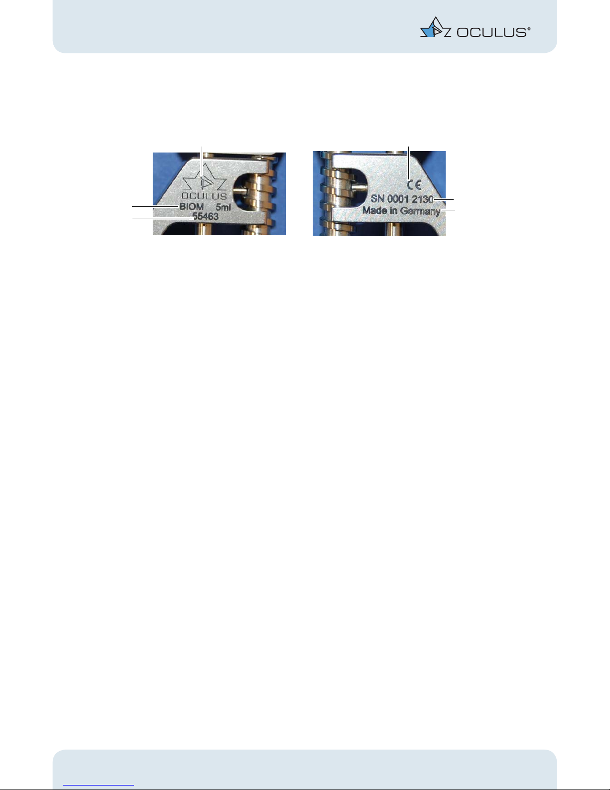
2 Graphic Symbols on the Equipment
3 Safety Instructions
3.1 About this Manual
Carefully read through the Instruction Manual.
Keep the Instruction Manual in good condition near the device.
Observe the legal regulations with regard to accident prevention.
Read the separate operating instructions for the SDI® 4 and accesso-
ries.
Read the special packing notice included with the adapter and acces-
sories.
If you have also selected our company’s Stereoscopic Diagonal Inverter
(SDI 4), you will find this unit and its accessories in a lined, plastic carrying
case.
1 Company logo + Manufacturer 4 Country of manufacture
2 CE marking 5 Device number
3 Serial number 6 Device name
Fig. 2-1: Graphic Symbols on the Equipment BIOM® 5
1
3
4
6
5
2
Page 7
3 Safety Instructions
Instruction Manual BIOM® 5 (G/55400/0413/en) 3 / 40
3.1.1 Pictograms Used in this Manual
Attention
Identifies a potentially dangerous situation which may cause minor injury
or material damage.
Note
Denotes situations which could result in incorrect findings, denotes user instructions and useful or other important information.
Identifies important information about the product and its use, which require special attention.
3.2 Safety Instructions for Use
Attention
Personal injury or material damage due to improper operation
Observe the following safety instructions.
Personal injury or material damage due to equipment modifications that
could jeopardize safety
No modifications may be made to this device without the permission
of the manufacturer.
Instructions for Operating Personnel
Ensure that the BIOM® 5 is only used by duly trained physicians and
OR-personnel, who, based on their qualifications or their knowledge
and practical experience, can guarantee proper handling of the device.
Page 8

3 Safety Instructions
4 / 40 Instruction Manual BIOM® 5 (G/55400/0413/en)
Instructions for Setup and Connection
Also comply with the legal provisions in force in your country, and
with the hygiene and waste disposal regulations of the hospital or
clinic.
Never mount or dismount the BIOM® 5 above a patient.
Assembly and instruction in the use of the BIOM® 5 and its accessories will
be done by an OCULUS employee or by a person authorized by OCULUS.
Instructions for Operation and Maintenance
Prior to use: Let OCULUS or an authorized dealer train you in the op-
eration of the BIOM® 5.
Never put a damaged BIOM® 5 into operation.
Only operate the BIOM® 5 with the original accessories supplied by us
and only when the unit is in a technically perfect condition.
Only operate the device if you have understood the operating instruc-
tions.
The BIOM® 5 and all sterilizable BIOM® 5 components must be sterilely
conditioned
prior to the first use
after every use
It is imperative that you heed the cleaning, disinfection and steriliza-
tion instructions given in the Conditioning Manual.
Page 9
4 Proper Use
Instruction Manual BIOM® 5 (G/55400/0413/en) 5 / 40
3.2.1 Instructions for Use
Attention
Risk of eye injury if the working distance of the BIOM® 5 to the patient is
changed
When swiveling the BIOM® 5 into the work position (into the beam path)
you must comply with the following instructions:
Do not use the coarse adjustment knob at the microscope stand.
Do not adjust the height of the stand arm over the surgical field, ei-
ther by motor or manually.
Do not change the patient’s position by adjusting the height of the
operating table.
Heed the focusing instructions, sect. 9.7, page 20.
Heed the instructions for visualisation of the posterior segment of the
eye, sect. 9.8, page 21.
Heed the practical information for use of the BIOM® 5, sect. 9.9,
page 23.
Troubleshooting
If a fault occurs that you cannot rectify with the help of the trouble-
shooting table (Page 27), the unit must not be used! Clearly mark the
unit as non-operational and get in touch with our service personnel.
Instructions for Disassembly and Disposal
Dispose of the device according to legal regulations. Comply with the
hygiene and waste disposal regulations in force in the hospital or
clinic.
4 Proper Use
This Binocular Indirect OphthalmoMicroscope (BIOM® 5) is used for noncontact observation of surgeries in the posterior segment of the eye.
The BIOM® 5 is intended for use with compatible designed surgical microscopes in hospitals, clinics or other institutions for human medicine.
Use only surgical microscopes named by OCULUS Optikgeräte GmbH as
adaptable for the OCULUS.
Only operate the device using original accessory parts supplied by us, and
when the device is in technically correct working order.
Heed the safety instructions listed above.
Page 10
5 Device Description
6 / 40 Instruction Manual BIOM® 5 (G/55400/0413/en)
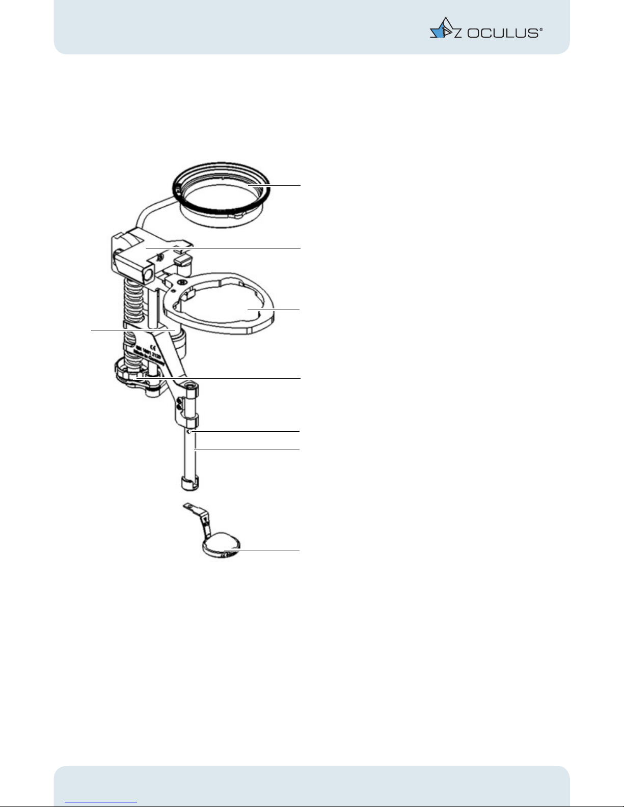
5 Device Description
BIOM® 5c
1 Reduction lens
(not supplied with the BIOM®)
2 Housing with swivel mechanism
3 Lens receptacle
4 Focus adjustment wheel
5 Control mark
6 Lensholder with safety rod
7 Front lens
(not supplied with the BIOM®)
8 Drive module
Fig. 5-1: Device overview BIOM® 5c with reduction lens and ophthalmoscopy lens
8
1
3
6
4
7
5
2
Page 11
5 Device Description
Instruction Manual BIOM® 5 (G/55400/0413/en) 7 / 40
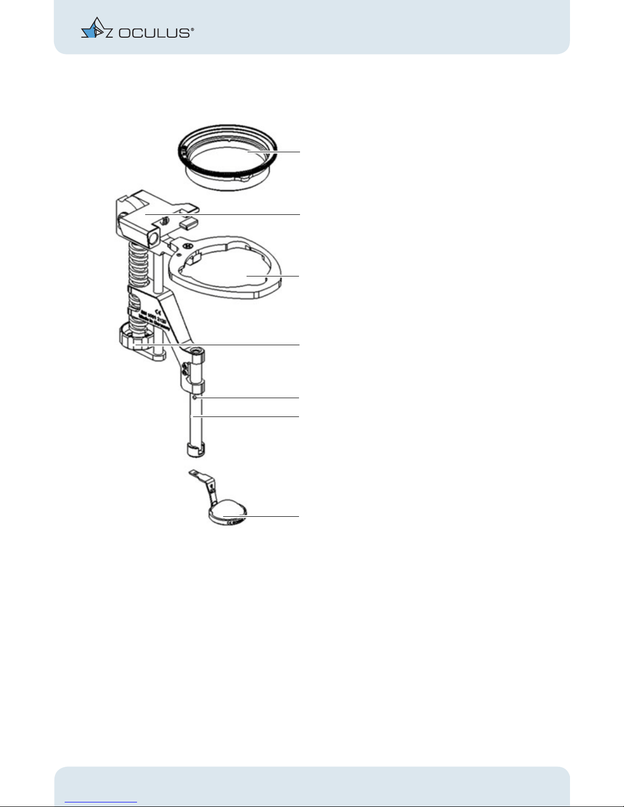
BIOM® 5m
5.1 Function of the BIOM® 5
The BIOM® 5 is used in conjunction with an SDI® (Stereoscopic Diagonal
Inverter) to erect the image for non-contact, wide-angle observation of the
fundus and vitreous body.
The combination of surgical microscope and the optical components of the
BIOM® 5 allows examination of the vitreous chamber under stereoscopic
conditions. The BIOM® 5 works as an indirect ophthalmomicroscope without corneal contact during the surgery.
1 Reduction lens
(not supplied with the BIOM®)
2 Adjuster, housing with swivel mechanism
3 Lens receptacle
4 Focus adjustment wheel
5 Control mark
6 Lens holder with safety rod
7Front lens
(not supplied with the BIOM®)
Fig. 5-2: Device overview BIOM® 5m with reduction lens and ophthalmoscopy lens
1
3
6
4
7
5
2
Page 12
6 Transport and Storage
8 / 40 Instruction Manual BIOM® 5 (G/55400/0413/en)
The patient’s eyeball can be moved freely during the surgery. Peripheral
fundus portions are thus easy to examine. This combined optical system
achieves a fundus view of up to 125° in total.
The optical system of the BIOM® 5 consists of the reduction lens and the
front lens. The reduction lens ensures that the distance between the patient’s eye and the surgical microscope remains more or less the same when
the BIOM® 5 is swiveled in and out. Individually adjusted to the respective
surgical microscope, the microscope objective’s focal distance is reduced.
The position of the reduction lens with respect to the surgical microscope
is preset.
The height adjustment of the front lens is used for focusing the BIOM® image. The distance between the surgical microscope and the front lens is set
using the adjusting wheel at the BIOM® 5.
For BIOM® 5c only:
Press the combination foot switch to focus by means of the electric motor.
This height adjustment of the front lens brings the fundus image into the
focal point of the microscope objective.
As the image is completely reversed when the BIOM® 5 is used, optimal use
is only guaranteed in conjunction with a SDI®. The SDI® rights the complete
image reversal and can be switched on and off as required.
6 Transport and Storage
The following values apply for a period of 6 months at most in the shipping
container.
The transport and storage conditions according to DIN EN ISO 601-1 are:
Attention
Risk of damage to the device due to improper transport and storage
Transport the BIOM® 5 carefully.
Store the BIOM® 5 under proper storage conditions.
An ambient temperature range of -40°C to +70°C
A relative humidity range of 10% to 100%,
including condensation
An air pressure range of 5o kPa to 106 kPa
Page 13

7 Connect the BIOM® 5c to the SDI® 3c
Instruction Manual BIOM® 5 (G/55400/0413/en) 9 / 40
7Connect the BIOM® 5c to the SDI® 3c
You need an adapter (Art. No. 54406) to connect the BIOM® 5c (4-pole) to
an SDI® 3c (2-pole).
Plug in the unsterile adapter at the 2-pole SDI® housing.
Carefully connect the sterilized plug of the BIOM® 5c to the adapter
plug, taking care to maintain the sterility.
To disconnect after use, take hold of the outer sleeve of the BIOM® 5c
plug and unlock the connection.
For more information, refer to the Instruction Manual for the adapter.
8 Initial Operation
8.1 Prior to Initial Operation
Remove the BIOM® 5 and its accessories from the packaging and dis-
pose of the latter in the proper manner.
Clean, disinfect and sterilize the BIOM® prior to initial use, fig. 12,
page 29.
Assembly and instruction in the use of the BIOM® 5 and its accessories will
be done by an OCULUS employee or by a dealer authorized by OCULUS.
8.2 Prior to Start-Up
An adapter is needed for attachment of the BIOM® 5. Check whether
it adapted to the respective surgical microscope type.
If necessary, extend the adapter.
A part of the mounting fixture generally remains installed at the mi-
croscope.
Clean, disinfect and sterilize the detachable adapter plate for the
BIOM® 5 prior to use, see sect. 12, page 29.
If, however, you do have to remove the mounting fixture for any
reason, proceed as shown on the assembly diagram provided with the
adapter.
Clean, disinfect and sterilize the BIOM® 5 prior to every use, sect. 12,
page 29.
Page 14
8 Initial Operation
10 / 40 Instruction Manual BIOM® 5 (G/55400/0413/en)
Check and Mount the Dovetail Connections:
First visually check the connection for correct mounting.
Check this by gently rocking the connection before you begin mount-
ing any of the other attachments.
Attention
Risk of injury to the patient if the BIOM® 5 drops.
Loose connections can pose a hazard if you mount the adapter plate incorrectly.
Therefore, after each conversion, check that all retaining elements (e.g.
locking screws) are present and are tight.
Page 15

9 BIOM® 5 in Use
Instruction Manual BIOM® 5 (G/55400/0413/en) 11 / 40
9BIOM® 5 in Use
9.1 Choose the Appropriate Optics
Use the appropriate reduction lens for the surgical microscope’s objec-
tive.
Select the appropriate front lens for the surgery.
Currently available front lens:
53603 Wide field, high definition lens with very good resolution in all
areas; can be used with maximum microscope magnification. With this
lens, the maximum field of view is approx. 60° to 125°. The outside diameter of the lens mount is 20 mm.
53606 Hi Res lens with very good resolution, can be used with maxi-
mum microscope magnification; with this lens, the maximum field of
view is approx. 60º and the working distance between the cornea and
front lens (bottom surface) is approx. 10 mm. The outside diameter of
the lens mount is 19 mm.
53604 90D lens with very good resolution; standard lens suitable for
most cases; with this lens, the maximum field of view is approx. 90º,
and the working distance is approx. 8 mm. The outside diameter of the
lens mount is 19 mm.
53602 Wide field (E)-lens with good resolution, large depth of focus;
lens with a maximum field of view of approx. 120º, and a working distance of approx. 3-4 mm. The outside diameter of the lens mount is 19
mm.
53601 Wide field lens for deepset eyes; with this lens the maximum
field of view is approx. 70°, and the working distance is approx. 3-4
mm. The outside diameter of the lens mount is 12 mm.
Note
Sterilize the front lenses in the steam autoclave.
Lens 53603 Lens 53606 Lens 53604 Lens 53602 Lens 53601
Page 16

9 BIOM® 5 in Use
12 / 40 Instruction Manual BIOM® 5 (G/55400/0413/en)
Disposable lens Sets
In addition to the re-sterilizable lenses, disposable sterile BIOM® Optic Sets
can also be used on the BIOM® 5.
The sets consist of a wide-angle front lens and a reduction lens, which can
be used for a microscope length of f=175 mm or f= 200 mm.
The maximum field of view is approx. 125° and the working distance is
approx. 3-4 mm.
The disposable lens sets can be combined with models BIOM® 5:
9.2 Assembly
Make sure that all components are present and are sterile.
Fig. 9-1: Disposable lenses (similar to those shown here)
Objekctiv
lens
Model BIOM® BIOM® Optic Set
for f=175 mm BIOM® 5m (55462)
BIOM® 5c (55400)
HD Professional 54411
for f=200 mm BIOM® 5ml (55463)
BIOM® 5cl (55403)
HD Professional 54412
for f=200 mm BIOM® 5m (55462)
BIOM® 5c (55400)
HD Flex 54415
Page 17

9 BIOM® 5 in Use
Instruction Manual BIOM® 5 (G/55400/0413/en) 13 / 40
BIOM® 5m Components
BIOM
®
5c Components
1 Housing with swivel mechanism 3 Front lens
2 Adapter plate 4 Reduction lens
Fig. 9-2: BIOM® 5m Components
1 Housing with swivel mechanism 5 Cable duct
2 Adapter plate 6 Reduction lens
3 Drive belt 7 Cable connector
4Front lens
Fig. 9-3: BIOM® 5c Components
4
1
2
3
6
1
2
4
5
3
7
Page 18
9 BIOM® 5 in Use
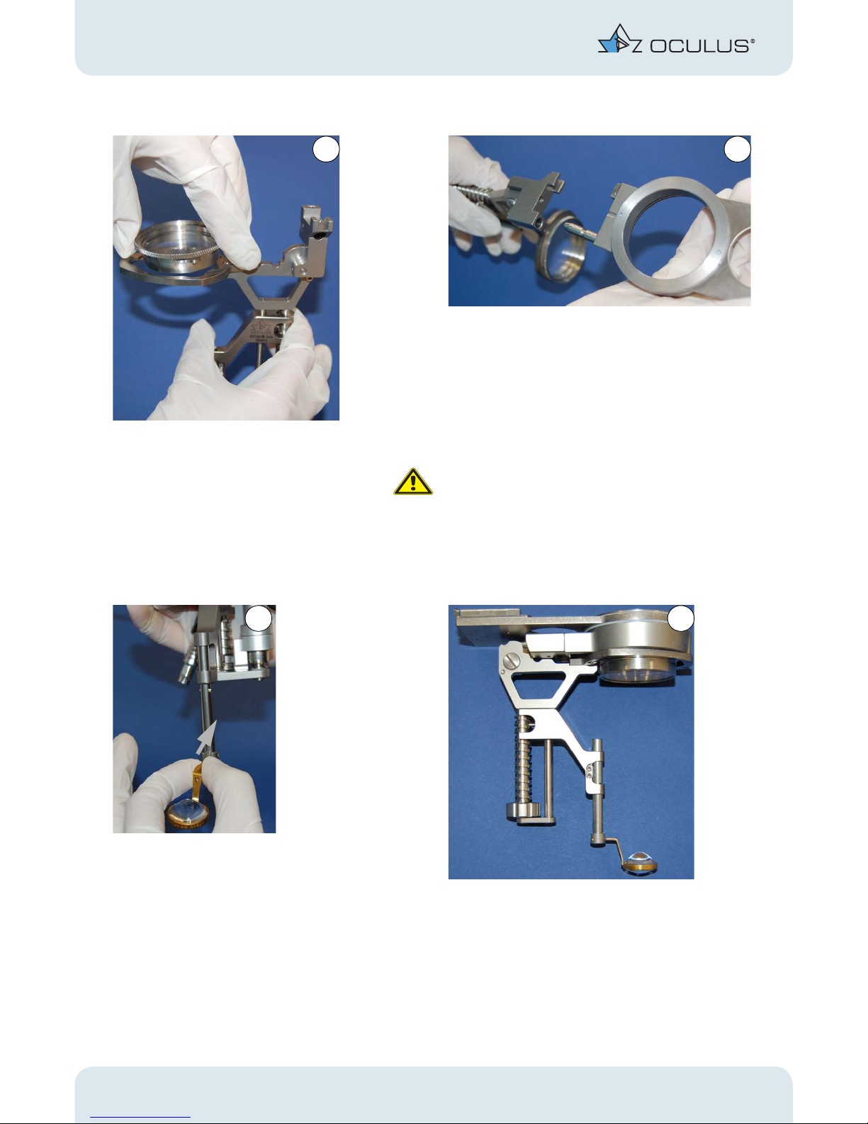
14 / 40 Instruction Manual BIOM® 5 (G/55400/0413/en)
Insert the reduction lens. Plug in the adapter plate. You must thereby over-
come the detent that secures the connection.
Attention
Risk of injury to the patient if the BIOM® 5 is inserted
incorrectly
If you do not insert the BIOM® 5 correctly, you will get
a decentered fundus image.
Make sure that the BIOM® 5 has been slipped on up to
the limit stop.
Insert the front lens. The BIOM® 5ml is fully assembled.
Fig. 9-4: Component assembly
1
2
3
4
Page 19

9 BIOM® 5 in Use
Instruction Manual BIOM® 5 (G/55400/0413/en) 15 / 40
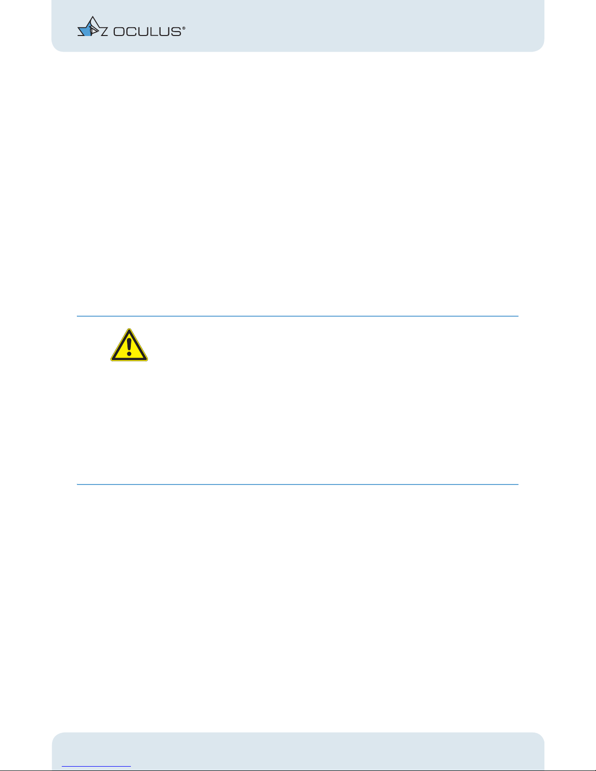
Additionally for the BIOM® 5:
You must insert the drive belt and put on a cable duct. The purpose of the
cable duct is to keep the connecting cable of the drive unit at the BIOM® 5c
(also fits the previous model) away from the unsterile microscope parts. The
cable duct and the drive belt can be steam autoclaved and are conditioned
in the same way as the other BIOM® 5 components.
Install the drive belt. First fasten the cable holder to the
connector
Then fit the other side over the cable.
Fig. 9-5: Installation of the drive belt and cable duct
5
6
Page 20

9 BIOM® 5 in Use
16 / 40 Instruction Manual BIOM® 5 (G/55400/0413/en)
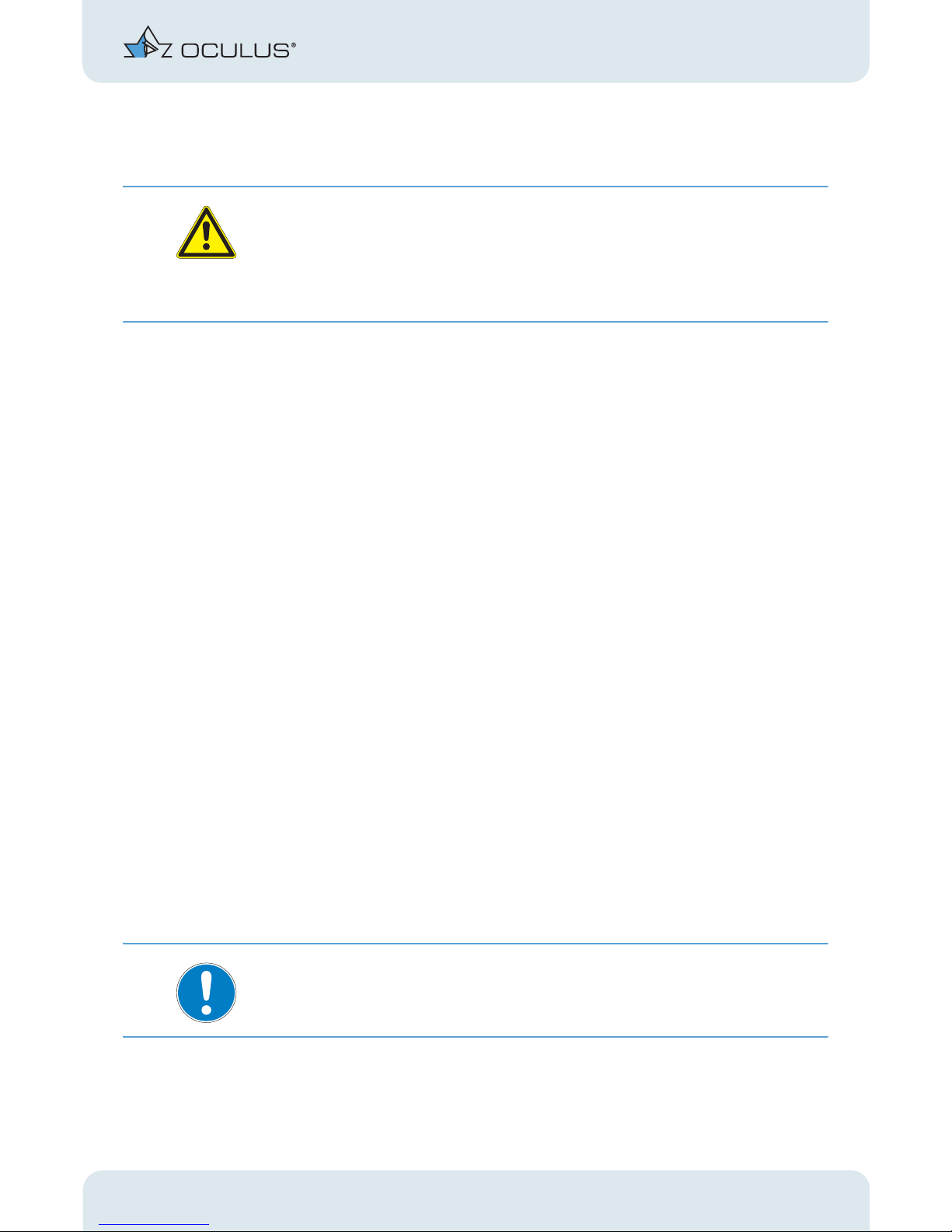
9.3 Under Sterile Conditions:
Test the Safety Functions
Attention
Risk of injury in the event of malfunction
Only use the BIOM® 5 after the following functions have been tested
and are in perfect working order.
#
Turn the BIOM® 5 towards the adapter plate. Make
sure that the housing body can be shifted without
resistance.
Slide the safety rod of the lens mount up and down
several times to check that it moves smoothly. The
control marking must be visible all times.
Check that the knob turns easily and shorten the
total length until the adjuster is at the uppermost
position.
Check whether all fastening screws are present
(e.g. screws at the feather key of the safety rod).
Fig. 9-6: Test the Safety Functions
1
2
control
marking
3
Page 21

9 BIOM® 5 in Use
Instruction Manual BIOM® 5 (G/55400/0413/en) 17 / 40
Prior to each use, check that:
The device is in technically perfect condition.
All connections and fasteners that can be loosened are properly
tightened and are in a safe condition.
The dovetail mount for the adapter is securely fastened at the
microscope.
9.4 Connect the BIOM® 5 to the
Microscope
Caution
Patient hazard caused by incorrect installation
Never mount the BIOM® 5 above a patient.
Push the sterile cap onto the knurled screw. Slide the adapter plate with the BIOM® 5 into the
dovetail mount at the microscope.
Secure the adapter into place with the knurled screw.
Fig. 9-7: Connect theBIOM® 5 to the Microscope
1
2
3
Page 22

9 BIOM® 5 in Use
18 / 40 Instruction Manual BIOM® 5 (G/55400/0413/en)
For BIOM® 5c only
For the BIOM® 5c, you must connect the control cable to the SDI® 4c.
Connect the control cable to one of the side couplers of the SDI® 4c.
Make sure that the cable does not touch any unsterile parts of the
microscope.
Fig. 9-8: Connect the control cable without touching the unsterile microscope parts
Fig. 9-9: BIOM® 5c: Connect the control cable
Page 23

9 BIOM® 5 in Use
Instruction Manual BIOM® 5 (G/55400/0413/en) 19 / 40
Connect the cable to the SDI®. The connector locks automatically.
Recommendation: If surgery is to be done on the left eye, connect the
control cable at the left hand side of the SDI®. When doing surgery on a
right eye, connect the control cable at the right hand side.
9.5 Swivel the BIOM® 5 to its
Parked Position
During extra-ocular surgery phases, swing the BIOM® out of the beam
path into the parked position.
When swinging out the BIOM®, push in the safety rod, including the
front lens, with you finger, until the rod reaches the limit stop.
☞
Lift up the safety rod and move to the endposition. Then release the
safety rod.
9.6 Make the Basic Settings at the
Microscope
Make the basic settings at the microscope in accordance with the
manufacturer’s specifications.
Adjust the microscope to the anterior eye segment and perform the
surgery steps under microscope illumination, including starting the
infusion.
Fig. 9-10: BIOM® 5 at its parked position
Page 24

9 BIOM® 5 in Use
20 / 40 Instruction Manual BIOM® 5 (G/55400/0413/en)
9.7 Instructions for Focusing the
BIOM
®
5m
Focusing on the BIOM® 5m is done manually with the adjusting wheel and
can also be done by a sterile assistant, who follows the surgery via a coobserver viewer.
Note
Adjust the ophthalmoscopy lens upwards for hyperopic eyes and
downwards for myopic eyes.
Attention
Risk of eye injury due to poor visibility conditions
If the surgeon works under poor visibility conditions, the use of intraocular
instruments can result in injury to the patient’s eyes.
When focusing the BIOM® 5, heed the following instructions.
Make sure that the microscope remains at this position (height) after
the surgical steps have been conducted at the anterior segment and
outside of the eye.
Before swinging it to the operating position, make sure that the BIOM®
5 has been set to the shortest overall length.
Before you begin to focus the BIOM® 5, check the distance from the
front lens to the patient’s eye.
Monitor the distance between the front lens and the eye while focus-
ing the BIOM® 5.
Fig. 9-11: Focusing with the adjusting wheel
Page 25
9 BIOM® 5 in Use
Instruction Manual BIOM® 5 (G/55400/0413/en) 21 / 40
Make sure that the front lens does not come into contact with the eye.
Do not adjust the working height of the microscope while focusing the
BIOM® 5.
Do not use the microscope’s focusing function while focusing the BI-
OM® 5.
For BIOM
®
5c only (focusing by electric motor):
Focusing of the BIOM® 5c is done by the surgeon by means of the combination foot switch while observing through the microscope.
Only use the BIOM® 5c’s motorised focusing function when the front
lens is far enough away from the patient’s eye.
The surgeon may only use the motorised focusing function when the
distance between the front lens and the eye is simultaneously monitored.
It must be ensured that the operator can stop the motorised focusing
function at any time.
Attention
Risk of eye injury if the working distance of the BIOM® 5 to the patient is
changed
When swiveling the BIOM® 5 into the work position (into the beam path)
you must comply with the following instructions:
Do not use the coarse adjustment knob at the microscope stand to
adjust the height.
Do not adjust the height of the stand arm over the surgical field,
either by motor or manually.
Do not change the patient’s position by adjusting the height of the
operating table.
9.8 Instructions for Visualization of the
Posterior Eye Segment
After all preparations for surgery in the posterior eye segment have been
completed, proceed as follows, without changing the microscope position!
Use a suitable endoillumination.
Swivel the BIOM® 5 into the beam path of the microscope. Lift up
safety rod and only release it again when the swung-in end position
has been reached.
The lens slides down to its designated position. This position has been
reached when the control marks are fully visible.
Turn off the microscope illumination.
Activate the SDI® to right the complete image reversal.
Page 26

9 BIOM® 5 in Use
22 / 40 Instruction Manual BIOM® 5 (G/55400/0413/en)
Only for combination BIOM® 5c / SDI® 4c:
The image reversal is deactivated when the BIOM® 5c is swiveled
out of the beam path.
The SDI® 4c is automatically activated when the BIOM® 5c is
swiveled to the working position.
The image reversal function is automatically controlled via the
position switch at the BIOM® 5c.
Irrespective of this function, the image reversal of the SDI® 4c
can also be optionally controlled with the combination footswitch.
At a low microscope magnification: Begin initial focusing of the
BIOM® 5-image by turning the BIOM® 5 adjusting wheel.
Magnify the image section by actuating the focus switch at the
microscope.
Then use the microscope footswitch control to zoom in to maximum
magnification. Now finely focus the image with the adjusting knob of
the BIOM® 5.
Only thus is a parfocal image (i.e. a sharp image at every
magnification) guaranteed.
For BIOM® 5c only: Adjust the sharpness of the image with the rocker
of the combination foot switch, both for initial focusing and for
parfocally setting the image.
Recommendation: Reduce afterwards the microscope magnification to the
degree necessary to achieve as large a fundus overview as possible.
The use of the focusing function with the microscope foot pedal when the
BIOM® 5 is in use only changes the size of the image field (“keyhole effect“).
Attention
Risk of eye injury if the surgeon works under poor visibility conditions.
During the entire process, ensure that the front lens cannot touch the
cornea, as otherwise the image may be impaired.
Keep the cornea moist with a suitable fluid to protect the cornea and
to gain a clear view of the fundus.
Page 27
9 BIOM® 5 in Use
Instruction Manual BIOM® 5 (G/55400/0413/en) 23 / 40
9.9 Practical Information for Use
Attention
Risk of eye injury as a result of uncontrolled head movements of the
patient.
Take suitable measures to suppress uncontrolled head movements of
the patient during the surgery.
Avoid any contact of the front lens with the cornea.
If the lens comes into contact with the cornea, the image immediately
becomes blurred.
In an extreme emergency, e.g. uncontrolled downward movement of
the microscope:
Stop with the Emergency Off button.
Pull or move the complete surgical microscope upwards.
Tilt the BIOM® 5 out of the beam path.
After a contact with the eye, swing the BIOM® 5 out, or slide the safety
rod upwards to facilitate cleaning of the optics, so that you can clean
the lens with a sterile swab.
Make sure that the cornea is sufficiently moistened with a suitable
solution. This will prevent damage to the cornea and will give you the
optimal view into the eye.
Adjustment of the microscope’s focus while the BIOM® 5 is in use acts as a
field diaphragm. The greater the distance between the eye and the
microscope, the smaller the angle of observation. This leads to the so-called
“keyhole effect”.
Focusing on the BIOM® 5m is done manually with the adjusting wheel and
can also be done by a sterile assistant, who follows the surgery via a coobserver viewer.
For BIOM® 5c only:
Focusing of the BIOM® 5c is done solely by the surgeon by means of the
combination foot switch while observing through the microscope.
Note
Adjust the ophthalmoscopy lens upwards for hyperopic eyes and
downwards for myopic eyes.
Page 28

9 BIOM® 5 in Use
24 / 40 Instruction Manual BIOM® 5 (G/55400/0413/en)
9.9.1 End Operation of the BIOM
®
5
Swivel the BIOM® 5 to its parked position.
After completing the surgery in the posterior segment: Slide up the
safety rod of the BIOM® 5 by hand and flip the BIOM® aside.
Deactivate the SDI®.
For the Combination BIOM
®
5c / SDI® 4c Only
Swiveling the BIOM® 5c out of the beam path automatically deactivates the
SDI® 4c.
9.10 Remove the BIOM® 5 from the
Microscope
Caution
Patient hazard caused by incorrect removing
Never dismount the BIOM® 5 above a patient.
BIOM® 5m
After completing the surgery:
Loosen the knurled screw, fig. 9-7, page 17, pict. 3.
Pull the BIOM® 5 along with the adapter plate off the dovetail mount,
fig. 9-7, page 17, pict. 2.
Page 29

9 BIOM® 5 in Use
Instruction Manual BIOM® 5 (G/55400/0413/en) 25 / 40
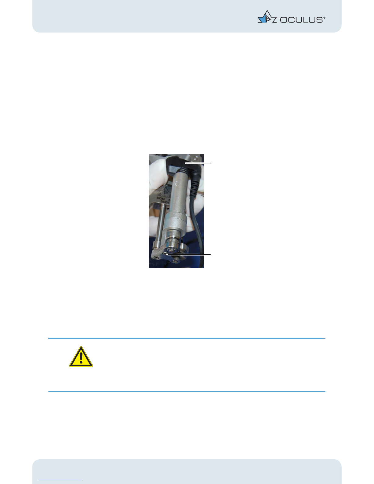
BIOM® 5c
After completing the surgery:
Note
Risk of damage to the device if the connector is pulled incorrectly.
If you pull on the cable, you could damage it and the complete drive module
would then have to be exchanged.l
Always grasp the plug connector of the BIOM® 5c at the sleeve to
release the locking mechanism.
Loosen the knurled screw, fig. 9-7, page 17, pict. 3.
Pull the BIOM® 5 along with the adapter plate off the dovetail mount,
fig. 9-7, page 17, pict. 2.
Pull the plug of the BIOM® 5c out of the coupler at
the SDI® 4c housing. To do this, grip the plug at the
sleeve and unlock it.
Detach the cable holder from the plug.
Take off the drive belt.
Abb. 9-12: Demounting the BIOM® 5 c components
1
2
3
Page 30
10 Troubleshooting
26 / 40 Instruction Manual BIOM® 5 (G/55400/0413/en)
9.11 Dismantle
Proceed in reverse order from assembly of the BIOM® 5.
Pull the BIOM® 5 off the adapter plate. To do so, swivel the BIOM® 5
out, fig. 9-4, page 14, pict. 2.
Dismount the two optics, fig. 9-4, page 14, pict. 1 and 3.
For BIOM® 5c only:
Remove the drive belt and the flexible cable duct (fig. 9.2, page 12)
from the BIOM® 5c.
Before sterilizing, check that the drive module (1) is secure. If it is
loose, either tighten the Allen screw, 2 mm (2) at the drive module or
call in your hospital technician.
All components are prepared for cleaning, disinfection and sterilization in
the steam autoclave, see sect. 12, page 29.
10 Troubleshooting
Attention
If an error occurs which you are unable to correct by following the instructions below, label the device as “out of order” and contact our service department. (Address: sect. 14.2, page 34).
Never put a damaged BIOM® 5 into operation.
Fig. 9-13: Drive module: Check and tighten
1
2
Page 31

10 Troubleshooting
Instruction Manual BIOM® 5 (G/55400/0413/en) 27 / 40
Troubleshooting Chart - BIOM® 5
Error Possible Cause Help
The safety rod of the BIOM® 5 is
sticking
The BIOM® 5 must not be used in
this condition!
Deposits on the BIOM® 5 due
to inadequate sterilization
Foreign body in safety rod ex-
tension channel
The rod is bent
Careful mechanical cleaning
and switch over to a better demineralized water; clean the
BIOM® 5 with ultrasound.
Careful mechanical cleaning
and removal of the foreign
body
Clean the BIOM® 5 in an ultra-
sound bath
Treat the rod with a suitable,
silicone oil-free lubricant prior
to the next sterilization
Send the BIOM® 5 to OCULUS
service department
Loose adapter
Dovetail mount wobbles
The locking screws are
loose
Screws are loose
Tighten the locking screws by
hand
Tighten the screws with a suit-
able screwdriver
Cropped or
decentered image
The SDI®, other attachments
or the BIOM® 5 adapter have
been mounted crookedly
The magnifying lens clip is
bent or mechanically damaged
Correct the assembly
Carefully bend the magnifying
lens clip back into shape or replace it
Unclear image Soiled glass surfaces
The glass surfaces have been
damaged during sterilization
The glass surfaces have been
mechanically damaged
The ophthalmoscopy lens is in
contact with the eye
In contact with the eye
Dry patient cornea
Clean the glass surfaces
Change the sterilization meth-
od, replace lenses if necessary
Greater care in use and stor-
age of lenses; replace if necessary
Correct the working distance,
clean the lens surfaces
Moisten the cornea regularly
with a suitable solution
Page 32

10 Troubleshooting
28 / 40 Instruction Manual BIOM® 5 (G/55400/0413/en)
Unfocused image BIOM® 5 is maladjusted
A reduction lens is not being
used
The reduction lens is not com-
patible the microscope objective
Focus the BIOM® 5 in accor-
dance with the instructions
given in the manual
Use a reduction lens
Check the engraving on the re-
duction lens and change the
lens, if necessary (see sect. 9.1,
page 11
Fundus view is too narrow Too much distance between
the ophthalmoscopy lens and
the eye
Magnification of the
microscope system to high
Carefully reduce the distance
using the microscope fine
adjustment mechanism
Reduce magnification of the
microscope
The eye or the lens reflect strongly The microscope light is on Turn the light off, illuminate
only intraocular
The BIOM® 5 cannot be detached
from the adapter
The BIOM® 5 has not been
swiveled out
Vacuum has developed be-
tween the BIOM® 5 and the
adapter, or there are deposits
on the connecting parts
Swivel out the BIOM® 5 for
detachment
Place the BIOM® 5 and adapter
into an ultrasound bath (for
approx. 5 min)
No function whatsoever when the
combination control unit is actuated
The combination control unit
is not connected to the SDI®
4c
The SDI® 4c is not connected
to the 6V-15V power supply
Power failure or power outlet
is not active
These are not active when the
sockets at the microscope
stand are in use
Establish the connection to the
SDI® 4c
Establish the connection to the
6V-15V power supply
Inform the in-house
electrician
Use the 6V-15V plug
transformer
Use the mechanical adjusting
element or adjusting wheel
Activate the sockets in
accordance with the
instructions for the stand
Contact the microscope
manufacturer for assistance
Error Possible Cause Help
Page 33

11 Change the Drive Module
Instruction Manual BIOM® 5 (G/55400/0413/en) 29 / 40
11 Change the Drive Module
Proceed as described in the Assembly Instructions for the drive
module.
12 Cleaning, Sterilization and Maintenance
12.1 Condition Components
Condition the BIOM® 5 and all BIOM® components before the first and
every subsequent use so that they are sterile.
Malfunction when using the
combination control unit
5-pole plug has been forcibly
plugged in the wrong way
round
Plug it in the right way round
(pay attention to the lug and
slot of the polarity reversal
protection)
Motorised focusing not possible with
the
BIOM® 5c when using the
combination control unit
BIOM® 5c connector not
plugged into the SDI® 4c
properly
Defective drive belt
Drive belt missing
Connecting cable damaged
Defective drive module
Plug in the connector correctly
Install a new, sterile drive belt
or focus manually using the
focusing knob at the BIOM® 5c
Install a sterile drive belt
Exchange the drive module
Exchange
Error Possible Cause Help
Page 34

12 Cleaning, Sterilization and Maintenance
30 / 40 Instruction Manual BIOM® 5 (G/55400/0413/en)
To clean, disinfect and sterilize the equipment, proceed as described in
the Conditioning Manual
.
Attention
Risk of infection if reconditioning is done incorrectly.
Please heed the separate Conditioning Manual.
Note
The sterilization tray from the company OCULUS Optikgeräte GmbH (Art.
No. 55185) can also be used for cleaning the BIOM® components.
Cleaning and Sterilization Instructions
The BIOM® 5, the adapter and the optics can be cleaned in a dishwasher
with a mild alkaline cleaning agent and can be cleaned and disinfected in
the disinfector (refer to the Conditioning Manual).
Due to the special surface finish required for sterilizability of the BIOM® 5,
structural patterns may become visible. This unavoidable minor blemish
does not in any way adversely affect the function, handling and sterilization
of the unit.
All of the components of the BIOM® 5 listed in sect. 16.1, page 36, the
adapter and the presently available reduction lenses and front lenses,
except for the disposable lens sets, can be steam-autoclaved (134°C).
Fig. 12-1: Specially designed insert for sterilization containers. Loaded with the BIOM® 5c setup
Page 35

12 Cleaning, Sterilization and Maintenance
Instruction Manual BIOM® 5 (G/55400/0413/en) 31 / 40
The OCULUS Optikgeräte GmbH company offers a sterilization container
with a specially designed insert for keeping the BIOM® 5, optical
components and the adapter plate in place for optimum care during and
after sterilization
Do not use aggressive cleaning agents that contain chlorine or
solvents, nor abrasive or sharp-edged cleaning products to clean the
unit.
Always heed the product descriptions and directions for use of
products you use to disinfect.
Maintenance
Maintenance oil (examples):
Aesculap Sterilit i (JG600) oil spray
Aesculap Sterilit i (JG598) Instrument oil
Medicon instrument oil spray 46.00.40
in USA: JG598 Sterilit I Drip Feed Oiler
If the moving parts are sluggish: After cleaning and prior to steriliza-
tion, treat all moving parts of the BIOM® 5 with a sterilizable, silicone
oil-free conditioning lubricant.
Remove any excess oil from the surfaces, as staining could otherwise
occur.
Clean and Sterilize
Cleaning materials: Damp cloth
Clean the BIOM® 5 with water immediately after use. This prevents
incrustations which can make complete sterilization more difficult
Always remove the optical system components before autoclaving. All
components of the BIOM® 5 listed in sect. 16, page 36 can be sterilized
in a steam autoclave (max. 134°C).
Attention
Risk of function impairment in association with the use of mineralized
water
If you use mineralized water, mineral deposits can form on the device and
impair its function.
Use only demineralized, filtered water for steam sterilization.
Risk of damage to the device if STERRAD® is used for sterilization
The use of STERRAD® for sterilization purposes can damage the BIOM® 5.
Do not use STERRAD® for sterilization purposes.
Page 36

13 Disposal of Used Devices
32 / 40 Instruction Manual BIOM® 5 (G/55400/0413/en)
Clean and Sterilize the Reduction Lens and Ophthalmoscopy lens
The optics can either be doubly shrink-wrapped or secured in the sterilization insert from Oculus Optikgeräte GmbH for sterilization in the autoclave.
Dismantle the optical components of the BIOM® 5 before cleaning and
sterilizing it.
Stand the lenses and reduction lenses as vertical as possible during
sterilization to prevent water stains from forming on the optics.
Please be sure to heed the additional instructions given in the specific
instructions for use that are provided with all sterilizable OCULUS
products and sterilization and disinfection systems.
Avoid damage to the surface and its coating. Always place the compo-
nents of the optical system on a soft surface.
13 Disposal of Used Devices
Dispose of the BIOM® 5 according to legal regulations. Comply with
the hygiene and waste disposal regulations in force in the hospital or
clinic.
BIOM
®
5c
In accordance with Directive 2002/96/EC of the European Parliament and of the
Council of the 27th of January 2003, and the laws in force in the Federal Republic
of Germany governing the putting into circulation and taking back and
environmentally friendly disposal of electrical and electronic devices, old electrical
and electronic devices must be recycled and must not be disposed of with normal
household waste.
Page 37

14 Warranty and Service
Instruction Manual BIOM® 5 (G/55400/0413/en) 33 / 40
14 Warranty and Service
Please note the following warranty provisions:
Prior to and while operating the device it is important that you heed
the instruction manual and safety instructions.
In accordance with legal regulations, you are entitled to a warranty for
the BIOM® 5.
If modifications are made to the BIOM® 5 devices by unauthorized
persons, all warranty claims shall be voided. Improper modifications
and repairs may result in considerable hazards to users and patients.
Any entitlement to a warranty shall also be void if unauthorized
persons interfere with the supplied PC hardware and software.
Any transport damage must be reported immediately to the shipping
company. Have the transport damage noted on the bill of lading so
that complaint handling and compensation of damages can proceed
in an orderly manner.
In general, our Business and Shipping Terms on the date of purchase
apply.
14.1 Assumption of Liability for Functions and Damage
OCULUS will only accept responsibility for the safety, reliability and
serviceability of the BIOM® 5 if the unit is used in compliance with the
following terms:
Only use the equipment in conformance with this instruction manual.
There are no parts either on or inside the BIOM® 5 that require
maintenance or repair by the user. If assembly work, modifications,
adjustments, repairs, changes or service is performed by unauthorized
personnel, or if the BIOM® 5 is improperly maintained or handled, then
any liability by OCULUS is voided.
Exeption: Replacing the drive unit of the BIOM® 5.
If the above-referenced work is performed by authorized persons,
request a certification of the scope and type of repair, and, if
necessary, the changes to the standard values or to the operating
range from the service technician. This certification must contain the
date of performance and statement of the performing company, with
signature.
If requested, OCULUS will provide the service technician with a list of
spare parts and additional descriptive material for this purpose.
Make certain that only original OCULUS parts are used.
Page 38

14 Warranty and Service
34 / 40 Instruction Manual BIOM® 5 (G/55400/0413/en)
14.2 Manufacturer and Service Address
Supplemental information is available from our Service Department or from
our authorized representatives. Manufacturer and Service address:
Germany:
OCULUS Optikgeräte GmbH
Münchholzhäuser Straße 29
D 35582 Wetzlar
Tel.: +49 641 2005-0
Fax: +49 641 2005-295
E-mail: sales@oculus.de
www.oculus.de
USA:
OCULUS, Inc.
17721 59th Avenue NE
Arlington
WA 98223-1337
Tel. +1 425-670-9977
Fax +1 425-670-0742
e-mail: sales@oculususa.com
http://www.oculususa.com
Page 39

15 Declaration of Conformity
Instruction Manual BIOM® 5 (G/55400/0413/en) 35 / 40
15 Declaration of Conformity
KONFORMITÄTSERKLÄRUNG /
DECLARATION DE CONFORMITE /
DECLARATION OF CONFORMITY /
DICLARATIONE DE CONFORMITA /
DECLARATION DE CONFORMITA
OCULUS Optikgeräte GmbH
Münchholzhäuser Str.29
D-35582 Wetzlar
Tel: ++49 641 / 20 05 – 0
Fax: ++49 641 / 20 05 - 255
Wir / Nous / We / Noi / Nosotros OCULUS Optikgeräte GmbH
Erklären in alleiniger Verantwortung, dass das Medizinprodukt
déclarons sous notre propre responabilité que le dispositif médical
declare on our own responsibility that the medical device
dichiariamo sotto propria responsabilitá che il dispositivo medico
declaramos en sola responsabilidad que el producto medicina
GMDN-Code: 32237 Loupe, diagnostic/surgical
Name
/ nom / name / nome / nombre
Binokulares-Indirektes-Ophthalmo-Mikroskop /
Antriebsmodul zum Biom
Binocular Indirect Ophthalmomicroscope /
Motor unit for Biom
Typ / type ou modél / type or model /
tipo o modello / Tipo y modelo
54160 BIOM® 3e, 54162 BIOM® 3m, 54163 BIOM® 3ml,
54200 BIOM® 3c, 54203 BIOM® 3c, 54205 Antriebsmodul,
54462 BIOM® 4m, 54463,BIOM® 4ml 54400 BIOM® 4c,
54403 BIOM® 4cl, 54405 Antriebsmodul, 55400 BIOM® 5c,
55403 BIOM® 5cl, 55462 BIOM® 5m, 55463 BIOM® 5ml
und Zubehör
allen Anforderungen der Richtlinie 93/42/EWG inkl. Änderungen durch 2007 / 47 / EG entspricht.
meets all the provisions of the Directive 93/42/EEC included the changes 2007 / 47 / CE which apply to him.
remplit toutes les exigences de la 93/42/EEC y compris les modifications 2007 / 47 / CE qui le concernait
tutti i requisiti della direttiva 93/42/CEE, comprese le modifiche, entro il 2007 / 47 / CE
todos los requisitos de la Directiva 93/42/CEE, incluidas las enmiendas de 2007 / 47 / CE
Einstufung: (Richtlinie 93 / 42 / EWG, Anhang IX)
Classification: (MDD 93 / 42 / EEC, annex IX)
Classification: (MDD 93 / 42 / EEC annex IX)
Classificatione: (MDD 93 / 42 / EEC, annex IX)
Clasificatión: (MDD 93 / 42 / EEC annex IX)
I
Konformitätsbewertung nach: Richtlinie 93 / 42 / EG Anhang VII
Conformity according: MDD 93 / 42 / EEC, annex VII
Conformité en: MDD 93 / 42 / EEC, annex VII
Conformita a: MDD 93 / 42 / EEC, annex VII
Conformidad para : MDD 93 / 42 / EEC, annex IVII
Angewandte harmonisierte Normen:
Normes harmonisées appliquées:
Applied harmonized standards:
Norme armonizzate applicate
Norma armonizaciónada
DIN EN ISO 15004
DIN EN 554
Ort, Datum /
lieu, date / place, date / luogo, data / lugar, fecha
Name und Funktion /
nom et fonction / name and function / nome e funzione / nombre y function
Wetzlar, 19.04.2013
Geschäftsführer / Managing Director
OCULUS Optikgeräte GmbH
Dipl.-Ing. Rainer Kirchhübel
Page 40

16 Order Information, Accessories and Replacement Parts
36 / 40 Instruction Manual BIOM® 5 (G/55400/0413/en)
16 Order Information, Accessories and Re-
placement Parts
16.1 Components for the BIOM® 5
Basic Unit
Accessories for BIOM
®
5c / BIOM® 5cl
Optical Components for the BIOM
®
5
Ophthalmoscopy lenses
Component Order no.
BIOM® 5c 55400
BIOM® 5cl 55403
BIOM® 5m 55462
BIOM® 5ml 55463
Component Order no.
Drive belts (pack of 10) 54176
Cable duct (pack of 5) 54178
Component Order no.
Reduction lens for f = 175 mm 55401
Reduction lens for f = 200 mm 55404
Component Order no.
Autoclavable lenses:
Wide-field lens, diameter 12 mm for BIOM® 5 53601
Wide-field (enhanced) lens for BIOM® 5 53602
Wide- field, high definition lens for BIOM® 5 53603
90 D lens for BIOM® 5 53604
Hi-Res lens for BIOM® 5 53606
Page 41

16 Order Information, Accessories and Replacement Parts
Instruction Manual BIOM® 5 (G/55400/0413/en) 37 / 40
Adaption Components for the BIOM® 5
Component Order no.
Adapter for Kaps SOM
Adapter for Leica M500/M501/M620 55445
Adapter for Leica M650/M690 55446
Adapter for Leica M822 55447
Adapter for Leica M820/ M841/ M844 55448
Adapter for Möller Ophtamic 900/ Hi-R 900/EOS 900/
Allegra 900
55440
Adapter für Takagi OM 8/OM 18 55418
Adapter for Topcon OMS 600/OMS 610/ OMS 650/
OMS 710/
OMS 800 Pro/ OMS 800 Standard/
OMS 850 Pro/ OMS 850 Standard
55441
Adapter for Zeiss:
OPMI VISU 150/160
OPMI VISU 200/210
Lumera® 700
Lumera® T
Zeiss Lumera® i
OPMI CS with Retrolux /CS
OPMI CS with Retroskop /CS
OPMI MDI/MDO/MDU
55423
Adapter for Zeiss OPMI 1/6 55424
Dovetail for Zeiss OPMI VISU/Lumera 54511
Distancing part for ring support objective at Zeiss OPMI 6 54535
Adapter for mounting to a 0° co-observer mount for Zeiss
OPMI 6
54536
Dovetail for Zeiss OPMI 1/6 54537
Dovetail for Zeiss MDO/Retrolux CS 54538
Distancing part Zeiss OPMI MD 54539
Distancing part for Möller Ophtamic 900 mit 20°-illumination unit
54639
Page 42

17 Technical Data
38 / 40 Instruction Manual BIOM® 5 (G/55400/0413/en)
16.2 Sterilization Components for the
BIOM
®
5
16.3 Stereoscopic Diagonal Inverter
Systems for the BIOM® 5
17 Technical Data
Dimensions BIOM® 5m and BIOM® 5c
Component Order no.
Sterilization container with tray for the BIOM® 5 and its
accessories
55180
Insert for sterlization container
55185
Paper filters for sterilization container (100 pcs/box)
55190
Component Order no.
SDI® 4c (6-15 V) 54320
SDI® 4e (6-15 V) 54300
SDI® 4m (mechanical) 54302
Types for Leica microscopes:
SDI® 4c (6-15 V) 54330
SDI® 4e (6-15 V) 54310
SDI® 4m (mechanical) 54312
Width 63 x 112 x 110-145 mm
(2.5 x 4.4 x 4.3-5.7 in)
Overall height approx. 123-158 mm
(4.8-6.2 in)
Travel of the safety rod approx. 29 mm (1.14 in)
Page 43

17 Technical Data
Instruction Manual BIOM® 5 (G/55400/0413/en) 39 / 40
Dimensions BIOM® 5ml and BIOM® 5cl
Weight
Operating Conditions for Optical System
Sterilization and Disinfection Procedures
Dimensions (W x D x H) 63 x 112 x 124-160 mm
(2.5 x 4.4 x 4.9-6.2 in)
Overall height approx. 137-173 mm
(5.4 - 6.8 in)
Travel of the safety rod
approx. 29 mm (1.14 in)
BIOM® 5m approx. 186 g (0.41 lbs)
BIOM® 5ml approx. 190 g (0.42 lbs)
BIOM® 5c approx. 250 g (0.56 lbs)
BIOM® 5cl approx. 260 g (0.57 lbs)
Reduction lens approx. 30 g (0.07 lbs)
Front lens: depending on the model approx. 3—10 g
(0.007 —0.02 lbs)
Temperature +10°C to +40°C
Humidity 30% to 70%
Air pressure 700 hPa to 1060 hPa
BIOM® 5
Steam autoclave, 134°C
Reduction lens (only the reduction lenses listed in
this manual)
Steam autoclave, 134°C
Ophthalmoscopy lens (only the lenses listed in this manual) Steam auto-
clave, 134°C
Adapter Steam auto-
clave, 134°C
Drive belt Steam auto-
clave, 134°C
Page 44

17 Technical Data
40 / 40 Instruction Manual BIOM® 5 (G/55400/0413/en)
The unit can be attached to the following microscopes:
Zeiss:
OPMI 1/6
OPMI CS with Retrolux /CS
OPMI CS with Retroskop /CS
OPMI MDI/MDO/MDU
OPMI VISU 150/ VISU 160
OPMI VISU 200 / VISU 210
OPMI Lumera®
OPMI Lumera® i
OPMI Lumera® T
OPMI Lumera® 700
Leica:
M500 / M501 / M620
M650 / M690
M820 / M822 / M840 / M841 / M844
Moeller:
Ophtamic 900 / Hi-R 900 / EOS 900 / Allegra 900
Takagi:
OM 8
OM 18
Topcon:
OMS 600 / OMS 610 / OMS 650
OMS 110
OMS 710
OMS 800 Standard / OMS 800 Pro
OMS 850 Standard / OMS 850 Pro
Kaps:
SOM
 Loading...