

Page 1
OCULUS BIOM® 5
INSTRUCTION MANUAL
Binocular Indirect Ophthalmo-Microscope
Page 2

Notes on this
Instruction Manual
The BIOM® 5 combines an ophthalmoscope with a surgical microscope. It
allows the vitreous cavity to be viewed under stereoscopic conditions, with
optimal image quality, with up to 125° non corneal-contact observation of
the fundus.
The BIOM® 5 has been manufactured and tested according to strict quality
criteria.
To ensure safe operation, it is essential that you use the device correctly. For
this reason, you should thoroughly familiarize yourself with the contents of
this instruction manual before operating the device. In particular, pay
attention to the safety instructions.
This operating manual describes the following BIOM® 5 models:
BIOM® 5c and 5cl (long version)
BIOM® 5m and 5ml (long version)
Except for the difference in length, the respective long version is identical with respect to handling and features.
The long versions should be used at microscope focal lengths of
f=200 mm
Due to ongoing development, the diagrams shown in the instruction manual may depict minor changes to the actual device delivered.
If you have any questions or would like additional information about your
device, please do not hesitate to contact us by mail or fax. Our service team
will gladly assist.
OCULUS Optikgeräte GmbH
OCULUS is certified according to DIN EN ISO 13485, setting high standards
of quality where development, manufacture, quality assurance and service
regarding the entire range of products are concerned.
i / iii Instruction Manual BIOM® 5 (G/55400/0215/en)
Page 3

Table of Contents
1 Scope of Delivery........................................................................................................................1
2 BIOM® 5 Symbols .......................................................................................................................2
3 Structure of the Documentation.......................................................................................... 3
4 Safety Instructions.....................................................................................................................3
5 Intended Use.................................................................................................................................6
6 Device Description......................................................................................................................7
7 Transport and Storage.............................................................................................................. 8
8 Initial Operation ..........................................................................................................................9
9 Use of the BIOM® 5 ...................................................................................................................9
10 Troubleshooting ........................................................................................................................20
11 Change the Drive Module .....................................................................................................23
12 Cleaning, Sterilisation and Maintenance........................................................................23
13 Disposal of Used Devices.......................................................................................................24
14 Guarantee and Service ...........................................................................................................25
15 Declaration of Conformity....................................................................................................27
16 Order Information, Accessories and Replacement Parts..........................................28
17 Technical Data............................................................................................................................30
Table of Contents
4.1 About this Manual ......................................................................................................3
4.1.1 Used Graphic Symbols.........................................................................3
4.2 Safety Instructions for Use ..................................................................................... 4
4.2.1 Instructions for Use ..............................................................................5
6.1 Mode of Operation of the BIOM® 5.....................................................................8
8.1 Before Initial Operation ............................................................................................9
8.2 Before First Use............................................................................................................9
9.1 Choose the Appropriate Optics..............................................................................9
9.2 Mounting the BIOM® 5...........................................................................................10
9.3 Under Sterile Conditions: Test the Safety Functions..................................13
9.4 Connect the BIOM® 5 to the Microscope........................................................14
9.5 Swing the BIOM® 5 to the Parked Position....................................................16
9.6 Make the Basic Settings at the Microscope ...................................................16
9.7 Instructions for Focussing the BIOM® 5m/ml...............................................17
9.8 During the Surgery ...................................................................................................18
9.9 After the Surgery.......................................................................................................18
14.1 Assumption of Liability for Functions and Damage ...................................25
14.2 Manufacturer and Service Address....................................................................26
16.1 Components for the BIOM® 5..............................................................................28
16.2 Sterilisation Components.......................................................................................30
16.3 Image Reversal Systems.........................................................................................30
Instruction Manual BIOM® 5 (G/55400/0215/en) ii / iii
Page 4

Table of Contents
iii / iii Instruction Manual BIOM® 5 (G/55400/0215/en)
Page 5

1Scope of Delivery
BIOM® 5c
Component Order no.
BIOM® 5c
Version BIOM® 5c
Version BIOM® 5cl
Sterilisable drive belts (10 of)
Sterilisable cable duct (1 of)
BIOM® 5m
1 Scope of Delivery
55400
55403
Version BIOM® 5m
Version BIOM® 5ml
Instruction Manual
Conditioning Instructions
Box with cover
G/55400/xxx/en
G/55185/xxx/en
55462
55463
Additional components needed for BIOM® 5
Needed Supplementary Components see
Reduction lens and front loupe sect. 9.1, page 9
Adaptor for surgical microscope (if necessary,
sect. 16.1, page 28
with additional adaption modules).
Stereoscopic diagonal inverter for erecting the
sect. 16.3, page 30
image
We reserve the right to make changes to deliverables as a part of any
technical improvements.
If transport damage is discovered from the shipment, please file a
complaint with the shipping company immediately.
Have the damage confirmed on the bill of lading so that an orderly
handling of the complaint for damages is possible.
Instruction Manual BIOM® 5 (G/55400/0215/en) 1 / 32
Page 6
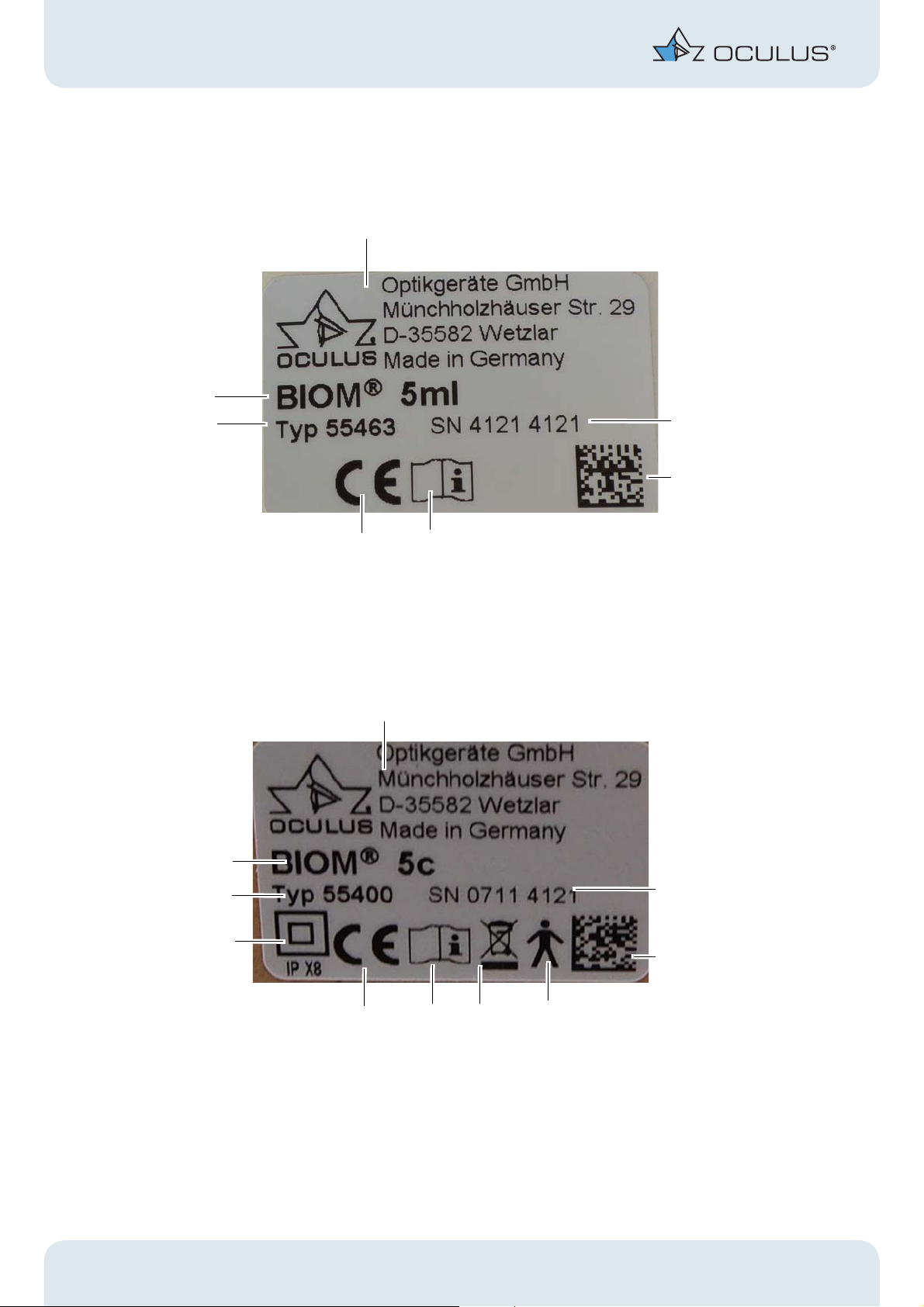
2 BIOM® 5 Symbols
1
2
3
7
6
4
5
1
2
3
7
10
8
94
5
7
2BIOM® 5 Symbols
1 Company logo + manufacturer 6 Device type
2 Serial number of the device 7 Name of device
3 Matrix 8 Applied part of the type B (BIOM® 5c and BIOM® 5cl only)
4 Heed Instruction Manual 9 Disposal with household waste is prohibited (BIOM® 5c and
BIOM® 5cl only)
5 CE marking 10 Protection class (BIOM® 5c and BIOM® 5cl only)
Fig. 2–1: Examples: BIOM® 5ml and BIOM® 5 symbols:
2 / 32 Instruction Manual BIOM® 5 (G/55400/0215/en)
Page 7
3 Structure of the Documentation
3 Structure of the Documentation
The following documents are supplied with the BIOM® 5:
Instruction Manual: The design of the unit is described in detail in
this document. You will also find all safety-related information for use
of the BIOM® 5.
Attention
All safety-related instructions for use of the BIOM® 5 are given in the instruction manual for the unit. It is therefore imperative that you read and
understand the whole instruction manual before you use the BIOM® 5.
Conditioning Instructions: These conditioning instructions explain
how to condition the BIOM® 5. They apply for the various models and
accessories of the BIOM® 5. You will also find an itemized list of the
articles concerned.
4 Safety Instructions
4.1 About this Manual
Carefully read through the instruction manual.
Keep the instruction manual in good condition, near to the device.
Observe the legal requirements for accident prevention.
Please read the separate operating instructions for the SDI® 4 and
accessories.
Please read the special packing notice included with the adaptor and
accessories.
If you have also selected our company’s Stereoscopic Diagonal Inverter
(SDI® 4), you will find this unit and its accessories in a lined plastic carrying
case.
4.1.1 Used Graphic Symbols
Attention
Denotes a potentially hazardous situation which can easily result in minor
physical injury or property damage.
Instruction Manual BIOM® 5 (G/55400/0215/en) 3 / 32
Page 8
4 Safety Instructions
Note
Denotes situations which could result in incorrect findings, denotes user
instructions and useful or other important information.
Denotes important information about the product and its use, which
require special attention.
4.2 Safety Instructions for Use
Attention
Risk of personal injury or property damage due to improper operation
Observe the following safety instructions.
Risk of personal injury or property damage due to equipment modifications
that could jeopardize safety
This equipment may not be modified without the permission of the
manufacturer.
Instructions for operating personnel
Ensure that the BIOM® 5 is used only by duly trained physicians and
operating theatre personnel, who, due to their training or their
knowledge and practical experience, can guarantee proper handling of
the device.
Transport and storage instructions
Refer to the notes in sect. 7, page 8.
Instructions for setup and connection
Comply with the legal provisions in force in your country, and with the
hygiene and waste disposal regulations of the hospital or clinic.
Never mount and dismount the BIOM® 5 over the patient.
Installation and instruction in the use of the BIOM® 5 and its accessories
will be undertaken by an OCULUS employee or by a duly authorized OCULUS
representative.
4 / 32 Instruction Manual BIOM® 5 (G/55400/0215/en)
Page 9
4 Safety Instructions
BIOM® 5c and BIOM® 5cl: Do not use excessive force to connect the
electrical connectors to the OCULUS SDI® 4c.
If connection is not possible, check whether the plug fits in the socket.
If you find damage to the plug connector, have the damage corrected
by our service department.
Operation and maintenance information
Before initial operation: Let OCULUS or an authorized dealer train you
in the operation of the BIOM® 5.
Never operate a damaged BIOM® 5.
Only operate the BIOM® 5 using original accessory parts supplied by
us, and when the device is in technically perfect working order.
Only operate the equipment after your have read and understood the
instruction manual.
The BIOM® 5 and all sterilisable BIOM® 5 components must be
sterilised:
Before the first use
After every use
It is imperative that you heed the cleaning, disinfection and
sterilisation instructions given in the conditioning manual.
4.2.1 Instructions for Use
Attention
Risk of eye damage if the working distance between the BIOM® 5 and the
patient changes
When the BIOM® 5 is swung into the working position (into the beam path),
the following instructions must be followed:
Do not use the coarse adjustment knob at the microscope stand to
adjust the height.
Do not adjust the height of the stand arm, either by motor or
manually, over the surgical area.
Do not change the patient’s position by adjusting the height of the
operating table.
Pay attention to the focussing instructions, sect. 9.7, page 17.
More information can be found in the Application tips: BIOM® 5 and
can be downloaded from the OCULUS website.
Instruction Manual BIOM® 5 (G/55400/0215/en) 5 / 32
Page 10

5 Intended Use
Troubleshooting
If a fault occurs that you cannot rectify with the help of the trouble-
shooting table (page 21), the unit must not be used! Clearly mark the
unit as non-operational and get in touch with our service personnel.
Instructions for disassembly and disposal
Dispose of the equipment in compliance with the corresponding legal
requirements. Comply with the hygiene and disposal regulations of
the hospital or clinic.
EMC and electrical safety information
The BIOM® 5c, a connected SDI® 4c and a microscope form a medical
electrical system (ME system) according to DIN EN 60601-1. If you connect
additional devices, those devices become part of the ME system.
Make sure that all devices of the ME system meet the requirements of
IEC 60601-1 or IEC 60950-1
5 Intended Use
This binocular indirect ophthalmomicroscope (BIOM® 5) is used for noncontact observation of surgeries in the posterior segment of the eye.
The BIOM® 5 is intended for use with compatible surgical microscopes in
hospitals, clinics or other institutions for human medicine
The surgical microscopes must be declared as adaptable by OCULUS Optikgeräte GmbH
Only operate the device using original accessory parts supplied by us, and
when the device is in technically perfect working order.
Make certain that the following connection types are used for the
power supply:
6 / 32 Instruction Manual BIOM® 5 (G/55400/0215/en)
Page 11
6 Device Description
8
1
2
3
4
5
6
7
BIOM® 5c BIOM® 5m
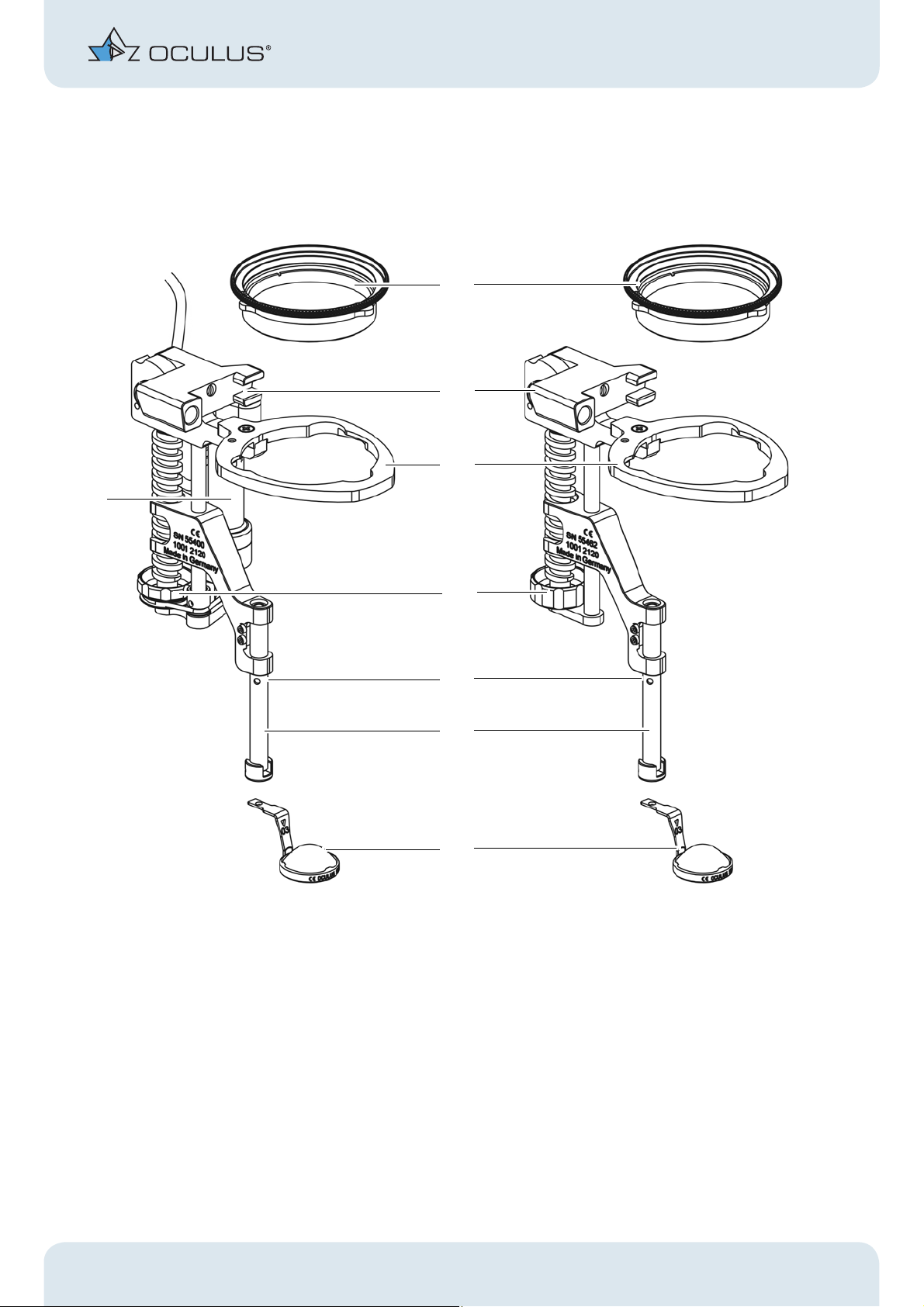
6 Device Description
1 Reduction lens (not supplied with the BIOM®) 5 Control mark
2 Housing with swivel mechanism 6 Loupe holder with safety rod
3 Lens receptacle 7 Ophthalmoscopy magnifying loupe
4 Focus adjustment wheel 8 Drive module (BIOM® 5c and BIOM® 5cl only)
Fig. 6–1: Device Overview, BIOM® 5 with reduction lens and ophthalmoscopy loupe
(not supplied with the BIOM®)
Instruction Manual BIOM® 5 (G/55400/0215/en) 7 / 32
Page 12

7 Transport and Storage
6.1 Mode of Operation of the BIOM® 5
The BIOM® 5 is used in conjunction with an SDI (Stereoscopic Diagonal
Inverter) to erect the image for non-contact, wide-angle observation of the
fundus and vitreous body. If the matching OCULUS SDI® is used, full
compatibility with the BIOM® 5 models is guaranteed.
The combination of surgical microscope and the optical components of the
BIOM® 5 allows examination of the vitreous chamber under stereoscopic
conditions. The BIOM® 5 works as an indirect ophthalmomicroscope
without corneal contact during the surgery.
The patient’s eye ball can be moved freely during the surgery. Peripheral
fundus portions are thus easy to examine. This combined optical system
achieves a fundus observation of approx. 125° in total.
The optical system of the BIOM® 5 consists of the reduction lens and the
front loupe. The reduction lens provides a virtually constant distance
between the patient’s eye and the surgical microscope when the BIOM® 5
is swung in or swung out. The reduction lens reduces the focal length of the
microscope objective lens.
The position of the reduction lens with respect to the surgical microscope
is preset.
The height adjustment of the front loupe is used for focussing the BIOM
image. The distance between the surgical microscope and the front loupe is
set using the adjusting wheel at the BIOM® 5.
For the BIOM® 5c/cl only:
Press the combination foot switch to focus by means of the electric motor.
This height adjustment of the front loupe brings the fundus image into the
focal point of the microscope objective.
As the image is completely reversed when the BIOM® 5 is used, optimal use
is only guaranteed in conjunction with a stereoscopic diagnonal inverter
(SDI®). The SDI® rights the complete image reversal and can be switched on
and off as required.
7 Transport and Storage
Attention
Equipment damage due to improper transport and storage
Transport the BIOM® 5 with care.
Store the BIOM® 5 in accordance with the transport and storage re-
quirements, the applicable national regulations and the regulations of
your hospital. See also sect. 17, page 30
8 / 32 Instruction Manual BIOM® 5 (G/55400/0215/en)
Page 13

8 Initial Operation
8.1 Before Initial Operation
Remove the BIOM® 5 and its accessories from the packaging.
Clean, disinfect and sterilise the BIOM® 5 before putting it into use for
the first time, sect. 12, page 23.
Installation and instruction in the use of the BIOM® 5 and its accessories
will be undertaken by an OCULUS employee or by an OCULUS authorized
dealer.
8.2 Before First Use
Make sure that the BIOM® 5 and its components have been cleaned,
disinfected and sterilised, also refer to the conditioning instructions
8 Initial Operation
9 Use of the BIOM® 5
9.1 Choose the Appropriate Optics
Use the appropriate reduction lens for the surgical microscope’s
objective.
Select the appropriate front loupe for the surgery.
The following front loupes can be steam-autoclaved:
53603
Wide-field high definition loupe
53606
Hi-res loupe
53602
Wide-field (E) loupe
53601
Wide-field loupe for deep-set eyes
53604
90D loupe
Instruction Manual BIOM® 5 (G/55400/0215/en) 9 / 32
Page 14

9 Use of the BIOM® 5
6
1
2
4
5
3
Disposable Loupe Sets
Objective
Lens
for f=175 mm BIOM® 5m (55462)
BIOM® Model BIOM® Optic Set
HD Professional 54411
BIOM® 5c (55400)
for f=200 mm BIOM® 5ml (55463)
HD Professional 54412
BIOM® 5cl (55403)
for f=200 mm BIOM® 5m (55462)
HD Flex 54415
BIOM® 5c (55400)
9.2 Mounting the BIOM® 5
Make sure that all components are present and are sterile.
Example: Components of the BIOM
®
5cl
1 BIOM® 5cl 4 Ophthalmoscopy magnifying
loupe
2 Adaptor plate 5 Cable duct (BIOM® 5c/cl only)
3 Drive belt (BIOM® 5c/cl only) 6 Reduction lens
Fig. 9–1: Components of the BIOM® 5cl
10 / 32 Instruction Manual BIOM® 5 (G/55400/0215/en)
Page 15

1
2
3
4
Insert the reduction lens. Then turn the reduction
lens clockwise until it reaches the stop.
9 Use of the BIOM® 5
Plug in the adaptor plate until it reaches the stop.
Attention
Risk to the patient if the BIOM® 5 is plugged in incorrectly
If you do not plug in the BIOM® 5 correctly, you will get
a decentred fundus image.
Insert the loupe until it reaches the stop. The BIOM® 5ml is now fully mounted.
Fig. 9–2: Mounting the components
Instruction Manual BIOM® 5 (G/55400/0215/en) 11 / 32
Page 16

9 Use of the BIOM® 5
5
6
Additionally for BIOM® 5c/cl:
You must insert the drive belt. You can put on a cable duct. The cable duct
is used to keep the connecting cable of the drive unit at the BIOM® 5c/cl
away from unsterile parts of the microscope.
Insert the drive belt Fasten the cable duct at the connector plug first
Then push the semi-open duct part over the cable.
Fig. 9–3: Mounting the drive belt and cable duct
12 / 32 Instruction Manual BIOM® 5 (G/55400/0215/en)
Page 17

9 Use of the BIOM® 5
1
2
3
1
9.3 Under Sterile Conditions: Test the
Safety Functions
Attention
Risk of injury due to improper function
Only use the BIOM® 5 when the following functions have been
checked and are in proper working order.
Flip the BIOM® 5 towards the adaptor plate. Make
sure that the housing body can be shifted without
resistance.
Check that the knob turns easily and shorten the
total length of the BIOM® 5 until the adjuster is at
the fully up position.
Fig. 9–4: Test the safety functions
Slide the safety rod of the loupe holder up and
down several times to check that it runs smoothly.
Check whether all fastening screws are present
(e.g. screws at the feather key of the safety rod).
The control mark (1) must be below the guide.
Instruction Manual BIOM® 5 (G/55400/0215/en) 13 / 32
Page 18

9 Use of the BIOM® 5
1
2
3
Before each use, check that
The unit is in technically perfect condition.
All connections and fasteners that can be loosened are properly
tightened and are in a safe condition.
The dovetail mount for the adaptor is securely fastened at the
microscope.
9.4 Connect the BIOM® 5 to the Microscope
Attention
Risk of injury to the patient if mounting is done incorrectly
Never mount the BIOM® 5 over the patient.
Push the sterile cap onto the knurled screw. Push the adaptor plate with the BIOM® 5 into the
dovetail mount at the microscope until it reaches
the stop.
Secure the adaptor into place with the knurled
screw.
Fig. 9–5: Connect the BIOM® 5 to the microscope
14 / 32 Instruction Manual BIOM® 5 (G/55400/0215/en)
Page 19

9 Use of the BIOM® 5
For BIOM® 5c/cl only
For the BIOM® 5c/cl, you must connect the control cable with the SDI® 4c.
Fig. 9–6: BIOM® 5c/cl: Connecting the control cable
Also connect the control cable to one of the side couplers of the SDI®
4c.
Make sure that the cable does not touch any unsterile parts of the
microscope.
Connect the cable at the SDI® 4c. The connector locks into place
automatically.
Instruction Manual BIOM® 5 (G/55400/0215/en) 15 / 32
Page 20

9 Use of the BIOM® 5
9.5 Swing the BIOM® 5 to the Parked Posi-
tion
During extra-ocular surgery phases, swing the BIOM® 5 out of the
beam path into the parked position.
When swinging out the BIOM, push in the safety rod, including the
front loupe, with you finger, until the rod reaches the limit stop.
Fig. 9–7: BIOM® 5cl in the working position Fig. 9–8: BIOM® 5cl at parked position
When swinging into the beam path:
Lift up safety rod and only release it again when the swung-in end
position has been reached.
9.6 Make the Basic Settings at the
Microscope
Adjust the microscope to the anterior eye segment and perform the
surgery steps under microscope illumination, including starting the
infusion.
16 / 32 Instruction Manual BIOM® 5 (G/55400/0215/en)
Page 21

9 Use of the BIOM® 5
9.7 Instructions for Focussing the BIOM®
5m/ml
Focussing on the BIOM® 5m is done manually with the adjusting knob, and
on the BIOM® 5c/cl, also by means of a foot pedal.
Fig. 9–9: Focussing with the adjusting knob
Attention
Risk of eye injury due to poor visibility conditions
The use of intraocular instruments in poor visibility conditions for the
surgeon can result in injury to the patient’s eyes.
When focussing with the BIOM® 5, heed the following instructions.
Before you begin to focus the BIOM® 5, check the distance from the
ophthalmoscopy magnifying loupe to the patient’s eye.
When focussing the BIOM® 5, make sure that:
The microscope is left at this position (height) after the surgical
steps have been performed at the anterior section.
The BIOM® 5 has been set to the shortest length before you swing
it into the working position.
The ophthalmoscopy loupe does not touch the eye.
You do not adjust the height of the microscope.
You do not use the microscope’s focussing function.
Instruction Manual BIOM® 5 (G/55400/0215/en) 17 / 32
Page 22

9 Use of the BIOM® 5
Special Case „Air-filled eye“
During the fluid-air-exchange: Turn the focussing knob of the BIOM®
5 until the front lens reaches the highest position.
Use the microscope’s fine focus to enlarge the image section.
For the BIOM
®
5c/cl only (focussing with electric motor):
Focussing of the BIOM® 5c/cl is done by the surgeon by means of the
combination foot switch while observing through the microscope.
Only use the BIOM® 5c/cl’s motorized focussing function when the
front loupe is far enough away from the patient’s eye.
The surgeon may only use the motorized focussing function when the
distance between the ophthalmoscopy loupe and the eye is
simultaneously monitored.
It must be ensured that the surgeon can stop the motorized focussing
function at any time.
Attention
Risk of eye damage if the working distance between the BIOM® 5 and the
patient changes
When the BIOM® 5 is swung into the working position (into the beam path),
the following instructions must be followed:
Do not use the coarse adjustment knob at the microscope stand to
adjust the height.
Do not adjust the height of the stand arm, either by motor or
manually, over the surgical area.
Do not change the patient’s position by adjusting the height of the
operating table.
9.8 During the Surgery
Make sure that the cornea is sufficiently moistened with a suitable
solution.
9.9 After the Surgery
After the surgery, you must remove the BIOM® 5 from the microscope.
You must bring the BIOM® 5 and its components to the conditioning
station immediately after the surgery.
18 / 32 Instruction Manual BIOM® 5 (G/55400/0215/en)
Page 23

9 Use of the BIOM® 5
Attention
Incorrect detaching is hazardous to the patient
Never detach the BIOM® 5 over the patient.
To dismount the das BIOM® 5, swing it to its standby position.
BIOM® 5m/ml
Pull the BIOM® 5 off the adaptor plate.
Loosen the knurled screw, Fig. 9–5, page 14, Fig. 3.
Pull the adaptor plate off the dovetail mount.
Fig. 9–10: Pull off the adaptor plate
Bring the BIOM® 5 and its components to the conditioning station
immediately.
®
BIOM
Fig. 9–11: BIOM® 5c/cl: Disconnect the plug-in connectors
5c/cl
Pull the plug of the BIOM® 5c/cl out of the coupler at the SDI® 4c housing.
To do so, take hold of the connector at the sleeve to unlock the connector.
Instruction Manual BIOM® 5 (G/55400/0215/en) 19 / 32
Page 24

10 Troubleshooting
Note
Risk of damage to the unit if the plug is pulled incorrectly
If you pull on the cable, you could damage it and the complete drive module
would then have to be exchanged.
Always grip the plug of the BIOM® 5c/cl at the sleeve, in order to
release the lock.
Pull the BIOM® 5 off the adaptor plate
Loosen the knurled screw, Fig. 9–5, page 14, Fig. 3.
Pull the adaptor plate out of the dovetail mount, Fig. 9–10, page 19.
Bring the BIOM® 5 and its components to the conditioning station
immediately.
10 Troubleshooting
Attention
If a fault occurs which you are unable to correct by following the
instructions below, label the device as “out of order” and contact our service
department. (Address: sect. 14.2, page 26).
Never operate a damaged BIOM® 5.
Before returning to OCULUS: Condition the BIOM® 5 and its
components in accordance with the conditioning instructions.
20 / 32 Instruction Manual BIOM® 5 (G/55400/0215/en)
Page 25

Troubleshooting guide – BIOM® 5
Fault Possible cause Remedy
10 Troubleshooting
The safety rod of the BIOM® 5 is
stuck
BIOM® 5 must not be used in this
state!
Loose adaptor
Dovetail mount wobbles
Deposits on the BIOM® 5 due to
inadequate sterilisation
Foreign body in safety rod
extension channel
Safety rod is bent
The locking screws are loose
Screws are loose
Carefully mechanical cleaning
and change to a better
demineralised water, clean the
BIOM® 5 ultrasonically
Careful mechanical cleaning and
removal of the foreign body
Clean the BIOM® 5 in the ultra-
sound bath
Treat the rod with a suitable,
silicone oil-free lubricant prior
to the next sterilisation
Send the BIOM® 5 to OCULUS
Service
Tighten the locking screws by
hand
Tighten the screws with a
suitable screwdriver
Image is cropped or out-of-center The SDI®, other components, or
the BIOM® 5 adaptor are
incorrectly mounted at an angle
The magnifying lens clip is bent
or mechanically damaged
Unclear image Soiled glass surfaces
The glass surfaces have been
damaged during sterilisation
The glass surfaces have been
mechanically damaged
Ophthalmoscopy loupe is
touching the eye
Dry patient cornea
Correct the assembly
Send the loupe to
OCULUS Service for
readjustment
Clean the glass surfaces
Change the sterilisation method,
replace lenses if necessary
Greater care in use and storage
of lenses; replace if necessary
Choose the correct work
distance, clean the loupe
Moisten the cornea regularly
with a suitable solution
Instruction Manual BIOM® 5 (G/55400/0215/en) 21 / 32
Page 26

10 Troubleshooting
Fault Possible cause Remedy
Unfocussed image Incorrect adjustment of the
BIOM® 5
Focus the BIOM® 5 in
accordance with the
instructions
A reduction lens is not being
used
The reduction lens is not
compatible with the
microscope objective
Fundus view is too narrow Too much distance between
the ophthalmoscopy lens and
the eye
Magnification of the
microscope system to high
Use a reduction lens
Check the engraving on the
reduction lens and exchange
the reduction lens, if necessary
(see sect. 9.1, page 9
Carefully reduce the distance
using the microscope fine
adjustment mechanism
Reduce magnification of the
microscope
The eye or the lens reflects strongly The microscope light is on Turn the light off, illuminate
only intraocular
The BIOM® 5 cannot be detached
from the adaptor
BIOM® 5 has not been tilted to
the side
Mineral deposits on the con-
necting components of the
Tilt the BIOM® 5 to the side
Place the BIOM® 5 and adaptor
into an ultrasound bath (for
approx. 5 min)
BIOM® 5 and adaptor
No function whatsoever when the
combination control unit is actuated
The combination control unit
is not connected to the SDI®
4c
The SDI® 4c is not connected
to the 6V-15V power supply
Power failure or power socket
is not active
These are not active when the
sockets at the microscope
stand are in use
Establish the connection to the
SDI® 4c
Establish the connection to the
6V-15V power supply
Inform the in-house
electrician
Use the 6V-15V plug
transformer
Use the mechanical adjusting
element or adjusting wheel
Activate the sockets in
accordance with the
instructions for the stand
Contact the microscope
manufacturer for assistance
22 / 32 Instruction Manual BIOM® 5 (G/55400/0215/en)
Page 27

11 Change the Drive Module
Fault Possible cause Remedy
Malfunction when using the
combination control unit
5-pole plug has been forcibly
plugged in the wrong way
round
Motorized focussing not possible with
the
BIOM® 5c/cl when using the
combination control unit
BIOM® 5c/cl connector not
plugged into the SDI® 4c
properly
Defective drive belt
Drive belt missing
Connecting cable damaged
Defective drive module
11 Change the Drive Module
Plug it in the right way round
(pay attention to the lug and
slot of the polarity reversal
protection)
Plug in the connector correctly
Install a new, sterile drive belt,
or focus
manually using the focussing
knob at the BIOM® 5c/cl
Install a sterile drive belt
Exchange the drive module
Exchange
Proceed in the manner described in the assembly instructions for the
drive module.
12 Cleaning, Sterilisation and Maintenance
Attention
Risk of infection due to improper reconditioning
Bring the BIOM® 5 and its components to the conditioning station im-
mediately after the surgery.
Pay attention to the separate conditioning instructions.
Instruction Manual BIOM® 5 (G/55400/0215/en) 23 / 32
Page 28

13 Disposal of Used Devices
13 Disposal of Used Devices
Dispose of the BIOM® 5 in compliance with the corresponding legal
requirements. Comply with the hygiene and disposal regulations of
the hospital or clinic.
®
BIOM
In accordance with Directive 2002/96/EC of the European Parliament and of
the Council dated 27 January 2003, and also the Law of the Federal Republic
of Germany on the Commercialization, Recall and Environmentally
Compatible Disposal of Electrical and Electronic Equipment, old electrical
and electronic equipment must be sent out for recycling and may not be
disposed in household trash.
5c
24 / 32 Instruction Manual BIOM® 5 (G/55400/0215/en)
Page 29

14 Guarantee and Service
Please note the following guarantee provisions:
Prior to and while operating the device, it is important that you heed
the instruction manual and safety instructions.
The BIOM® 5 carries a guarantee to which you are entitled in
accordance with the legal provisions.
If modifications are made to the BIOM® 5 by unauthorized persons, all
guarantee claims shall be voided. Improper modifications and repairs
may result in considerable hazards to users and patients.
Any transport damage must be reported immediately to the shipping
company. Have the transport damage noted on the bill of lading so
that complaint handling and compensation of damages can proceed
in an orderly manner.
In general, our Business and Shipping Terms applicable on the date of
purchase shall apply.
14 Guarantee and Service
14.1 Assumption of Liability for Functions and Damage
OCULUS will only accept responsibility for the safety, reliability and
serviceability of the BIOM® 5 if the unit is used in compliance with the
following terms:
Only use the equipment in conformance with this instruction manual.
There are no parts on the BIOM® 5 that require maintenance or repair
by the user. If assembly work, modifications, adjustments, repairs,
changes or service are performed by unauthorized personnel, or if the
BIOM® 5 is improperly maintained or handled, then any liability by
OCULUS is voided.
Exception: Exchange of the BIOM® 5 drive module
If the above-mentioned work is performed by authorized persons, then
a certification of the work shall be requested from the service
technician in which any changes to factory defaults or to operating
ranges shall be stated. This certification must contain the date of
performance and statement of the performing firm, with signature.
If requested, OCULUS will provide to the service technician a list of
spare parts and additional descriptive material for this purpose.
Make certain that only original OCULUS parts are used.
Instruction Manual BIOM® 5 (G/55400/0215/en) 25 / 32
Page 30

14 Guarantee and Service
14.2 Manufacturer and Service Address
Supplemental information is available from our Service Department or from
our authorized representatives. Manufacturer and Service Address:
Germany:
OCULUS Optikgeräte GmbH
Münchholzhäuser Straße 29
35582 Wetzlar
Germany
Tel.: +49 (0) 641 2005-0
Fax: +49 (0) 641 2005-295
E-mail: sales@oculus.de
www.oculus.de
USA:
OCULUS, Inc.
17721 59th Avenue NE
Arlington
WA 98223-1337
Tel. +1 425-670-9977
Fax +1 425-670-0742
e-mail: sales@oculususa.com
web: http://www.oculususa.com
26 / 32 Instruction Manual BIOM® 5 (G/55400/0215/en)
Page 31

15 Declaration of Conformity
15 Declaration of Conformity
Instruction Manual BIOM® 5 (G/55400/0215/en) 27 / 32
Page 32

16 Order Information, Accessories and Replacement Parts
16 Order Information, Accessories and
Replacement Parts
16.1 Components for the BIOM® 5
Basic unit
Component Order no.
BIOM® 5c 55400
BIOM® 5cl 55403
BIOM® 5m 55462
BIOM® 5ml 55463
Accessories for the BIOM
Component Order no.
Drive belts (pack of 10) 54176
Cable duct (pack of 5) 54178
Optical components for BIOM
Component Order no.
Reduction lens for f = 175 mm 55401
Reduction lens for f = 200 mm 55405
Optical components for BIOM
Component Order no.
Reduction lens for f = 200 mm 55404
®
5c / BIOM® 5cl
®
5m/BIOM® 5c
®
5ml/BIOM® 5cl
Ophthalmoscopy loupes (autoclavable loupes)
Component Order no.
Wide-field lens, diameter 12 mm for BIOM® 5 53601
Wide-field (enhanced) lens for BIOM® 5 53602
Wide-field, high definition loupe for BIOM® 5 53603
90 D lens for BIOM® 5 53604
Hi-res loupe for BIOM® 5 53606
28 / 32 Instruction Manual BIOM® 5 (G/55400/0215/en)
Page 33

16 Order Information, Accessories and Replacement Parts
Adaption components for BIOM® 5
Component Order no.
For Alcon LuxOR
Adaptor plate
For Alcon LuxOR
Adaptor plate
Dovetail mount
Adaptor plate for Kaps SOM 55423
Adaptor for Leica M500/M501/M620 55445
Adaptor for Leica M650/M690 55446
Adaptor for Leica M822 55447
Adaptor for Leica M820/ M841/ M844 55448
TM
with Q-Vue
TM
without Q-Vue
55423
55423
54856
Adaptor for Möller Ophtamic 900/ Hi-R 900/EOS 900/
55440
Allegra 900
Adaptor for Takagi OM 8/OM 18 55418
Adaptor for Topcon OMS 600/OMS 610/ OMS 650/
55441
OMS 710/
OMS 800 Pro/ OMS 800 Standard/
OMS 850 Pro/ OMS 850 Standard
Adaptor plate for Zeiss:
55423
OPMI VISU 150/160
OPMI VISU 200/210
Lumera® 700
Lumera® T
Lumera® i
OPMI CS with Retrolux /CS
OPMI CS with Retroscope CS
OPMI MDI/MDO/MDU
Adaptor plate for Zeiss OPMI 1/6 55424
Dovetail for Zeiss OPMI VISU/Lumera® 54511
Spacer for ring support objective on Zeiss OPMI 6 54535
Adaption part for 0° co-observation holder on Zeiss OPMI 6 54536
Dovetail for Zeiss OPMI 1/6 54537
Dovetail for Zeiss MDO/Retrolux CS 54538
Spacer Zeiss OPMI MD 54539
Spacer for Möller Ophtamic 900 mit 20°-illumination unit 54639
Instruction Manual BIOM® 5 (G/55400/0215/en) 29 / 32
Page 34

17 Technical Data
16.2 Sterilisation Components
Component Order no.
Sterilisation container with insert for BIOM5 and accessories
Insert for sterilisation container
Paper filters for sterilisation container (100 pcs/box)
16.3 Image Reversal Systems
Component Order no. Component Order no.
SDI® 4c (6-15 V, 0.5 A) 54320 SDI® 4eli (6-15 V, 0.5 A) Leica 54332
SDI® 4e (6-15 V, 0.5 A)) 54300 SDI® 4m (mechanical) 54302
SDI® 4c (6-15 V, 0.5 A) Leica 54330 SDI® 4m (mechanical) Leica 54312
SDI® 4e (6-15 V, 0.5 A) Leica 54310 SDI® 4b (mechanical) 54301
SDI® 4cli (6-15 V, 0.5 A) Leica 54331 SDI® 4b (mechanical) Leica 54311
17 Technical Data
55180
55185
55190
Dimensions of the BIOM® 5
BIOM® 5m and BIOM® 5c BIOM® 5ml and BIOM® 5cl
Dimensions (W x D x H) 63 x 112 x 110-145 mm 63 x 112 x 124-160 mm
Total height approx. 123-158 mm approx. 137-173 mm
Travel of safety rod approx. 29 mm
approx. 29 mm
Weight
Product Weight Product Weight
BIOM® 5m
BIOM® 5ml
BIOM® 5c
approx. 186 g
approx. 190 g
approx. 250 g
BIOM® 5cl
Reduction lens
Front loupe: depending on the
model
approx. 260 g
approx. 30 g
approx. 3 — 10 g
30 / 32 Instruction Manual BIOM® 5 (G/55400/0215/en)
Page 35

Ambient Conditions, Transport and Storage Requirements for Optics
17 Technical Data
Temperature
Humidity
Air pressure
Operating conditions Transport requirements for BI-
OM® 5c and BIOM® 5cl, in acc.
with DIN EN 60601-1
+10°C to +40°C -40°C to +70°C -10°C to +55°C
30% to 70% 10% to 95% 10% to 95%
700 hPa to 1060 hPa 500 hPa to 1060 hPa 700 hPa to 1060 hPa
Storage requirements for BI-
OM® 5c and BIOM® 5cl, in
acc. With DIN EN 60601-1
These values apply to all BIOM® versions.
Sterilization and Disinfection Procedures
BIOM® 5
Reduction lens (only the reduction lenses listed in this manual) Steam autoclave, 134°C
Ophthalmoscopy loupe (only the loupes listed in this manual) Steam autoclave, 134°C
Adaptor Steam autoclave, 134°C
Drive belt Steam autoclave, 134°C
Steam autoclave, 134°C
BIOM® 5c and BIOM® 5cl: Classification according to IEC 60601 - 1
Type of protection against electric shock
Protection class 2
Degree of protection against electric shock Type B
Degree of protection against harmful penetration of water IPX8
Power supply via SDI® 4
Miscellaneous
Expected service life 4 years
Instruction Manual BIOM® 5 (G/55400/0215/en) 31 / 32
Page 36

17 Technical Data
The unit can be attached to the following microscopes:
Manufacturer
Alcon LuxOR
Zeiss: OPMI 1/6
Microscope
TM
OPMI CS with Retroscope 1/3 /CS
OPMI CS with Retroscope T/CS
OPMI MDI/MDO/MDU
OPMI VISU 150/ VISU 160
OPMI VISU 200 / VISU 210
OPMI Lumera
OPMI Lumera i
OPMI Lumera T
OPMI Lumera 700
Leica M500 / M501 /
M820 / M822 / M840 / M841 M844
M620 / M650 / M690
Möller Ophtamic 900 Hi-R 900 EOS 900 Allegra 900
Takagi OM 8 OM 18
Topcon OMS 600 / OMS 610 / OMS 650 OMS 110
OMS 710
OMS 800 Standard
OMS 800 Pro
OMS 850 Standard
OMS 850 Pro
Kaps SOM
32 / 32 Instruction Manual BIOM® 5 (G/55400/0215/en)
 Loading...