

TYPE R AUTOPILOT DRIVE UNIT SYSTEM PACKS
INSTALLATION MANUAL
OC15269 REV F 27 JULY 2012
POWERBOAT & SAILBOAT SYSTEMS

2 of 44
Subject to change without notice OC15269 REV F
Revision History
Revision Description
E Redesign in booklet format
F
See DCR # 0961
© 2012 Octopus Products Inc. All rights reserved.
The information contained in this document is the sole property of Octopus
Products Inc. Any reproduction in part or whole without the written permission of
Octopus Products Inc. is prohibited. Octopus Products Inc will nor be liable for
errors contained herein or for incidental or consequential damages in connection
with the furnishing, performance or use of this document.

WWW.OCTOPUSDRIVES.COM
WWW.OCTOPUSEUROPE.COM
CONTENTS
A Introduction
A1 System Overview . . . . . . . . . . . . . . . . . . . . . . . . . . . . . . . . . . . . . . . . . . . . .4
A2 Compatibility Information . . . . . . . . . . . . . . . . . . . . . . . . . . . . . . . . . . . . . . .4
A3 Important Safety Features . . . . . . . . . . . . . . . . . . . . . . . . . . . . . . . . . . . . . .5
A3a Manual Release . . . . . . . . . . . . . . . . . . . . . . . . . . . . . . . . . . . . . . .5
A3b Manual Override . . . . . . . . . . . . . . . . . . . . . . . . . . . . . . . . . . . . . . .5
B Mechanical Installation
B1 Available Space - Physical Envelope & Orientation . . . . . . . . . . . . . . . . . .6
B1a Drive Installation . . . . . . . . . . . . . . . . . . . . . . . . . . . . . . . . . . . . . . .7
B2 Outboard Engined Boats . . . . . . . . . . . . . . . . . . . . . . . . . . . . . . . . . . . . . . .8
B2a Engine compatibility . . . . . . . . . . . . . . . . . . . . . . . . . . . . . . . . . . . .8
B2b Supplied Parts . . . . . . . . . . . . . . . . . . . . . . . . . . . . . . . . . . . . . . . .8
B2c Installation. . . . . . . . . . . . . . . . . . . . . . . . . . . . . . . . . . . . . . . . . . . .8
B3 Sterndrive Boats Mercruiser DHB 1994+. . . . . . . . . . . . . . . . . . . . . . . . . .12
B3a Engine compatibility . . . . . . . . . . . . . . . . . . . . . . . . . . . . . . . . . . .12
B3b Supplied Parts . . . . . . . . . . . . . . . . . . . . . . . . . . . . . . . . . . . . . . .12
B3c Installation. . . . . . . . . . . . . . . . . . . . . . . . . . . . . . . . . . . . . . . . . . .13
B4 Sterndrive Boats Volvo Gasoline & Diesel USA 1997 Onwards . . . . . . . .16
B4a Engine compatibility . . . . . . . . . . . . . . . . . . . . . . . . . . . . . . . . . . .16
B4b Supplied Parts . . . . . . . . . . . . . . . . . . . . . . . . . . . . . . . . . . . . . . .16
B4c Installation. . . . . . . . . . . . . . . . . . . . . . . . . . . . . . . . . . . . . . . . . . .17
B5 Sterndrive Boats Mercruiser Saginaw 1983-93 . . . . . . . . . . . . . . . . . . . . .20
B5a Engine compatibility . . . . . . . . . . . . . . . . . . . . . . . . . . . . . . . . . . .20
B5b Supplied Parts . . . . . . . . . . . . . . . . . . . . . . . . . . . . . . . . . . . . . . .20
B5c Installation. . . . . . . . . . . . . . . . . . . . . . . . . . . . . . . . . . . . . . . . . . .21
B6 Sterndrive Boats Volvo Diesel Europe. . . . . . . . . . . . . . . . . . . . . . . . . . . .24
B6a Engine compatibility . . . . . . . . . . . . . . . . . . . . . . . . . . . . . . . . . . .24
B6b Supplied Parts . . . . . . . . . . . . . . . . . . . . . . . . . . . . . . . . . . . . . . .24
B6c Installation. . . . . . . . . . . . . . . . . . . . . . . . . . . . . . . . . . . . . . . . . . .25
B7 Inboard Engined Boats & Sailboats . . . . . . . . . . . . . . . . . . . . . . . . . . . . . .28
B7a Compatibility . . . . . . . . . . . . . . . . . . . . . . . . . . . . . . . . . . . . . . . . .28
B7b Supplied Parts . . . . . . . . . . . . . . . . . . . . . . . . . . . . . . . . . . . . . . .28
B7c Installation. . . . . . . . . . . . . . . . . . . . . . . . . . . . . . . . . . . . . . . . . . .29
B7d Quick Release . . . . . . . . . . . . . . . . . . . . . . . . . . . . . . . . . . . . . . .32
B7e Specification . . . . . . . . . . . . . . . . . . . . . . . . . . . . . . . . . . . . . . . . .32
B8 Routing Steering Cable . . . . . . . . . . . . . . . . . . . . . . . . . . . . . . . . . . . . . . .33
B8a Cable Length Calculation . . . . . . . . . . . . . . . . . . . . . . . . . . . . . . .33
B9 Connecting Steering Cable To Drive . . . . . . . . . . . . . . . . . . . . . . . . . . . . .34
B10 Rudder Feedback Unit (RFB) Installation & Calibration . . . . . . . . . . . . . .35
B10a Universal RFB Setup . . . . . . . . . . . . . . . . . . . . . . . . . . . . . . . . . .35
B10b Calibration and Installation . . . . . . . . . . . . . . . . . . . . . . . . . . . . . .36
B11 Interference Evaluation (Outboard Engines Only) . . . . . . . . . . . . . . . . . . .37
C Electrical Installation
C1 Connecting Drive To Autopilot . . . . . . . . . . . . . . . . . . . . . . . . . . . . . . . . . .38
C2 Rudder Feedback Unit . . . . . . . . . . . . . . . . . . . . . . . . . . . . . . . . . . . . . . . .38
C2a Connection - non Simrad autopilots . . . . . . . . . . . . . . . . . . . . . . .38
C2b Connection - Simrad autopilots . . . . . . . . . . . . . . . . . . . . . . . . . .39
D Appendix
D1 Accessories . . . . . . . . . . . . . . . . . . . . . . . . . . . . . . . . . . . . . . . . . . . . . . . .40
D2 General Maintenance Guide . . . . . . . . . . . . . . . . . . . . . . . . . . . . . . . . . . .41

A INTRODUCTION
A1 System Overview
The Octopus Type R Remote Drive is a rotary mechanical autopilot drive system which
makes it simple and economical to fit an autopilot on smaller powerboats with
mechanical push-pull cable steering or small sailboats with a steering quadrant or tiller.
The type R drive unit incorporates a drive motor, solenoid clutch and integrated rudder
feedback (RFB) capability. Its design means that the drive can be mounted in a
convenient position, meaning it will fit a large number of boats which because of
design constraints or size were not practical to have an autopilot fitted before.
The system uses a steering cable and connection kit which is fitted in addition to
the existing manual steering cable for cable steered boats or directly to the steering
quadrant for sailboats. This allows the system to be easily installed on most types of
boat without having to interfere with the existing steering system. There are five Type
R packs available which include the drive unit, 6ft (1.8m) steering cable and relevant
connection kit:
Part Number Type Compatibility
MDRESYS-A* Sterndrive Mercruiser 1994 onwards, Volvo Gasoline engines
and Volvo Diesel engines USA 1997 onwards
* We recommend changing the steering cable for a 9ft version when installing on to a twin engined boat.
MDRESYS-B Sterndrive Mercruiser Saginaw 1983-93, Volvo Diesel engines
Europe 1994 onwards
MDRESYS-C Outboard Yamaha 70hp+
MDRESYS-D Outboard Mercury, Mariner, Suzuki
MDRESYS-E Inboard/Sailboat Up to 32ft (9.75m) / 13,200lbs (6,000kg) displacement
A2 Compatibility Information
• The Type R Remote Drive is recommended for use on vessels with a maximum
speed of 44mph (65km/h) and should not be fitted to vessels which can exceed this.
• It should not be fitted to boats where the engine max horsepower exceeds the
max horsepower rating for the vessel as stated on the vessel manufacturer’s tag.
• The existing steering system MUST be capable of being back driven. The Type R
Remote Drive cannot be fitted if the steering system is a NFB (no feed back) type.
• The drive is designed to produce a maximum cable push/pull of 300lbs (136kg),
which makes it suitable for the vast majority of cable steered vessels. However
some vessels fitted with push pull cable steering systems have very stiff steering
or steering which is heavily loaded in one direction due to hull design and engine
considerations. Generally speaking, the Type R drive will steer vessels that do not
require more than a 15lb force on the rim of a 14in diameter steering wheel to hold
a course, this equals 105in-lb of torque. If the steering wheel input torque exceeds
this figure we would recommend that the vessel be fitted with a hydraulic linear
actuator drive system instead.
4 of 44
Subject to change without notice OC15269 REV F
WWW.OCTOPUSDRIVES.COM
WWW.OCTOPUSEUROPE.COM

A3 Important Safety Features
The Helmsperson should be made aware of the two following safety features before
using the Autopilot:
A3a Manual Release
The drive features a manual release in case the Autopilot is switched to manual
mode by mistake, which could result in a dangerous manoeuvre or violent movement of the steering wheel on a powerboat due to propeller action or trim forces.
While the drive is under consistent load from the boat’s steering system in one direction or no movement, the drive unit clutch will remain engaged when the Autopilot is
switched to manual mode.
To disengage the drive a small joggle action (turning the wheel/tiller from side to
side) will release the clutch and allow manual control.
IMPORTANT The helmsperson should always be ready to take manual control of
the boat when the Autopilot is returned to manual mode.
DOCKSIDE TESTING Due to the ‘Manual Release’ safety feature, when the vessel
is not in motion it might be necessary to joggle the wheel/tiller (move from side to
side) to engage or disengage the drive.
A3b Manual Override
IMPORTANT It is STRONGLY advised that the helmsperson be familiarized with
this manual override procedure before proceeding to sea.
In the event of uncontrolled automatic steering or any other emergency situation
where it is imperative that manual control be reassumed immediately, the helmsperson can override the steering action of the drive unit by exerting force on the steering wheel in the opposite direction to the drive. This action will cause the drive unit
thrust limit to “slip” allowing the helmsperson to take control.
NOTE The manual override does not disengage the autopilot - to resume full manual
control the autopilot should be switched to standby as soon as is practically pos-
sible.
5 of 44
Subject to change without notice OC15269 REV F
WWW.OCTOPUSDRIVES.COM
WWW.OCTOPUSEUROPE.COM
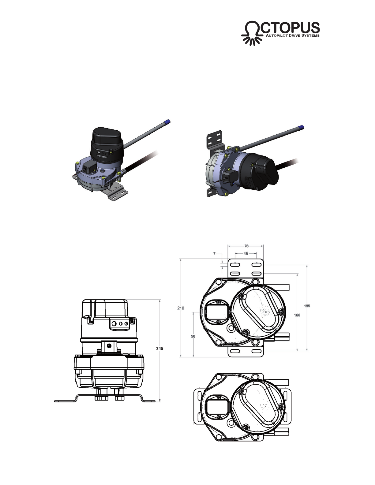
VERTICAL MOUNTHORIZONTAL MOUNT
Fig B1 - Mounting options
B MECHANICAL INSTALLATION
B1 Available Space - Physical Envelope & Orientation
The selected installation site should provide adequate space to accommodate the
drive unit including the entry and exit points for the steering cable. The drive can be
mounted at any angle. Note that no access for maintenance purposes is required.
The steering cable entry and exit ports are reversable, so the cable entry and exit
ports can be selected for the best installation arrangement on the particular vessel.
6 of 44
Subject to change without notice OC15269 REV F
WWW.OCTOPUSDRIVES.COM
WWW.OCTOPUSEUROPE.COM
Fig B2 - Physical drive envelope
BASEPLATE PERPENDICULAR MOUNT
BASEPLATE PARALLEL MOUNT
NOTE If the ports are reversed, the steering action will also be reversed. This can
be compensated for by adjusting the autopilot software or the drive motor wiring.
B1a Drive Installation
The design of the Type R Autopilot Drive System gives a high degree of flexibility in
the location of the drive unit relative to the steering mechanism, however factors
such as the optimum steering cable route and also the length of the steering cable
(6ft / 1.8m standard, other lengths available) will influence the final location.
It is recommended that the steering cable connection is the final stage of the
mechanical installation, but it is advisable to take into account the points raised in
section B8 regarding steering cable routing when planning the drive unit location.
i) Position the drive unit in the final location. Verify that there is sufficient clear-
ance for the steering cable entry and the spent cable tube, as well as access
for the electrical connections.
ii) Although there are no loads transferred to the drive unit mounting when the
autopilot is in operation, the selected location should be sturdy enough to
support the drive unit.
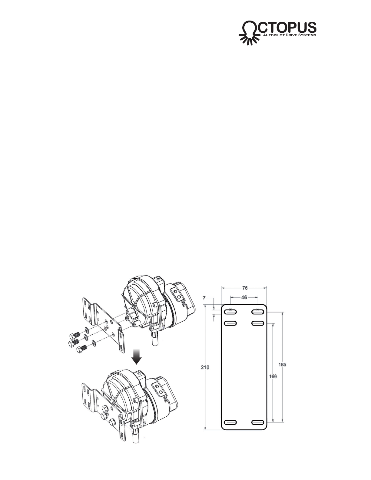
iii)
The drive base plate can be fitted in two possible orientations - perpendicular
or parallel. Assemble the base plate to the drive using the most suitable ori-
entation for the installation and torque the fasteners to 30-35in-lb (3.4-4.0Nm).
iii) Mark out the fixing pattern from the drive base plate and drill appropriate
sized pilot holes into the mounting structure (Fig B3). The mounting holes
are suitable for 1⁄4in or 6mm fasteners.
iv) Position the drive unit and install using suitable fasteners. Ensure they are
tightened securely.
7 of 44
Subject to change without notice OC15269 REV F
WWW.OCTOPUSDRIVES.COM
WWW.OCTOPUSEUROPE.COM
Fig B3 - Mounting plate drilling dimensions
B2 Outboard Engined Boats
The Outboard Installation Kits can be fitted to mechanical push-pull cable steered
vessels that are powered by MOST of the popular Yamaha (MDRESYS-C) and
Mercury/Mariner/Suzuki (MDRESYS-D) models of outboard engine. It is recommended for use on vessels with a maximum speed of 44mph and should NOT be fitted to vessels where the maximum horsepower of the engine exceeds the maximum
horsepower rating for the vessel as stated on the vessel manufacturer’s tag.
The installation kit allows the second steering cable for the Type R drive to be fitted
to the outboard steering system.
B2a Engine Compatibility
The MDRESYS-C kit is suitable for use on Yamaha 115-220 HP produced from
1984 onwards. The Yamaha engine has M6 (metric system) threaded fittings.
The MDRESYS-D kit is suitable for use on Mercury Black Max outboards from 1980
onwards, Mariner outboards from 1980 onwards, Mercury/Mariner 2.4 (all models)
and Suzuki DT75 – DT225 and DF60 – DF140. These engines have
1
⁄4in-28 UNF
threaded fittings.
B2b Supplied Parts
MDR-40 Type R Remote Rotary Autopilot Drive Unit
OC15SUK15A Yamaha Outboard Installation Kit (MDRESYS-C) OR
OC15SUK15B Mercury-Mariner-Suzuki Outboard Installation Kit (MDRESYS-D)
OC15109-6 6ft (1.8m) Secondary Steering Cable*
* Other lengths are available as optional accessories
B2c Installation
• Prepare the engine mounting site
i) Use the helm to centre the engine.
ii) Ensure that the area in front of the
tilt tube is clear of obstructing wires,
hoses etc. Reroute if necessary.
iii) There are four threaded holes on
the front face of the tilt tube (Fig B4),
ensure that these are free from paint
etc - retap if necessary:
MDRESYS-C M6 metric
MDRESYS-D
1
⁄4in-28 UNF
8 of 44
Subject to change without notice OC15269 REV F
WWW.OCTOPUSDRIVES.COM
WWW.OCTOPUSEUROPE.COM
Fig B4 - Threaded mounting holes on front face
of tilt tube
Threaded
mounting holes
Tilt tube
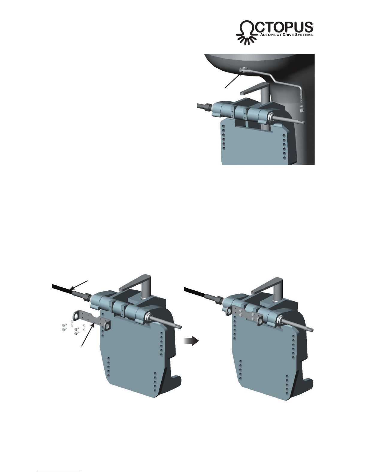
• Remove steering link arm
i) To simplify the re-assembly proce-
dure, make a note of the connections
between the steering link arm and the
manual steering cable and engine tiller.
ii) Disconnect the steering link arm from
the manual steering cable and the
engine tiller.
iii) Retain the link arm and fixings etc for
later use.
• Fit the secondary steering cable mount bracket to the engine tilt bracket
i) The bracket attaches to the four threaded mounting holes on the front face
of the tilt tube (Fig B6). Four M6/1⁄4in-28 UNF bolts and lockwashers are
supplied in the kit.
ii) Torque the bolts to 100in-lb (11Nm).
9 of 44
Subject to change without notice OC15269 REV F
WWW.OCTOPUSDRIVES.COM
WWW.OCTOPUSEUROPE.COM
Fig B5 - Removing steering link arm
Steering
link arm
Fig B6 - Fitting the cable mount bracket
Primary
steering cable
Mount bracket
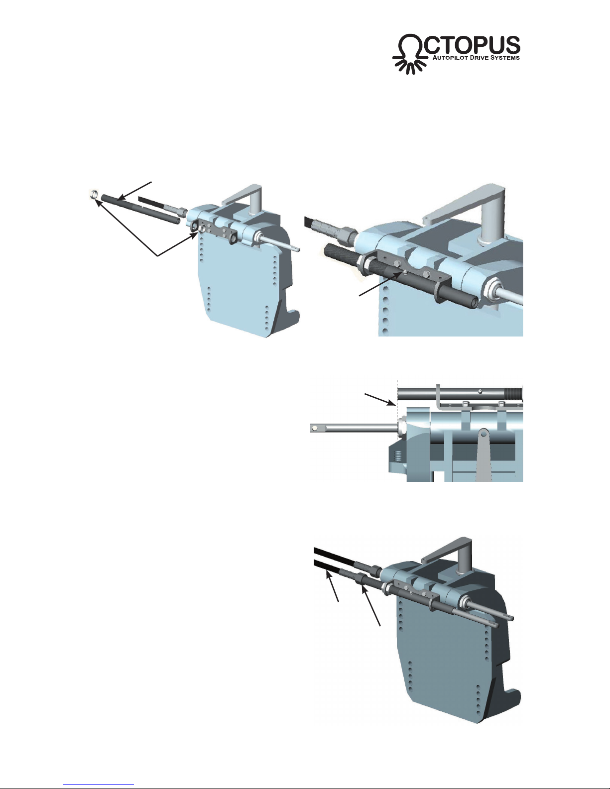
• Fit the cable guide tube to the cable mount bracket
i) Both the locknuts and the guide tube thread should be lubricated with marine
quality grease before assembly.
ii) Slide the guide tube into the cable mount bracket as shown (Fig B7).
10 of 44
Subject to change without notice OC15269 REV F
WWW.OCTOPUSDRIVES.COM
WWW.OCTOPUSEUROPE.COM
iii) Adjust the position of the guide
tube so that the exit end of the
guide tube aligns with the exit end
of the engine tilt tube (Fig B8)
iv)Tighten the two locknuts and
torque to 175in-lb (20Nm).
Grease the fitting.
Fig B7 - Fitting the cable guide tube
Cable guide
tube
Locknuts
Fig B8 - Cable guide tube alignment
TOP VIEW
Align
Greaser
• Attach the secondary steering cable to the guide tube
i) Both the cable nut, the guide tube
thread and the inside of the guide
tube should be liberally lubricated
with marine quality grease before
assembly.
ii) Insert the rod end of the secondary
steering cable into the threaded end
of the guide tube (Fig B9).
iii) Hand tighten the cable nut and
torque to 175in-lb (20Nm). The nut
has an internal locking thread
which
increases the amount of torque required
initially as the thread is cut.
Fig B9 - Secondary steering cable
Cable
nut
Secondary
steering
cable
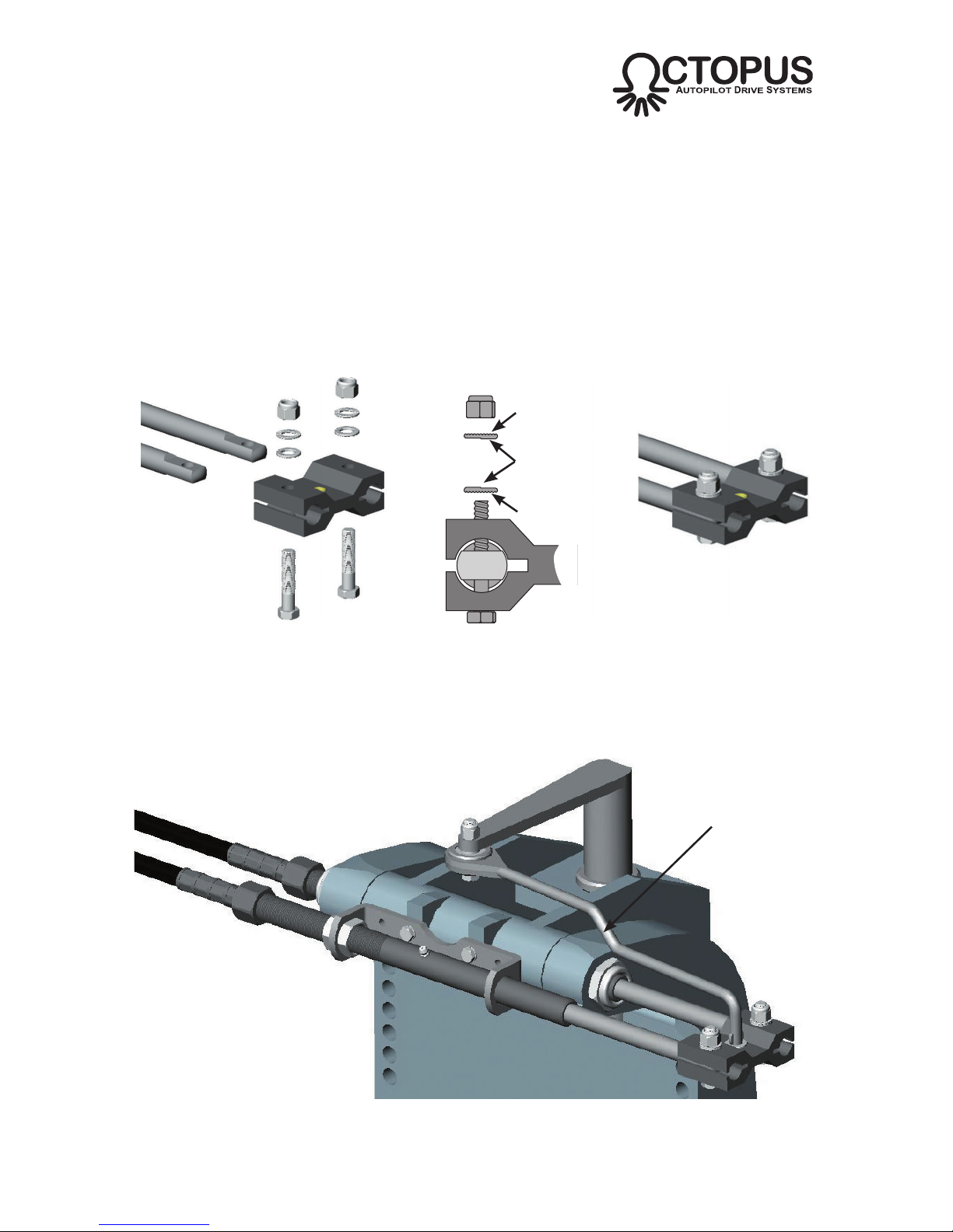
• Fit the dual block to the rod ends of the primary and secondary steering cables.
i) Disassemble the dual block assembly.
ii) Insert the two cable rod ends into the slots of the dual block.
iii) Align the crossholes and bolt through. The anti-vibration washers and nuts
supplied must be fitted in the correct order with the serrated face of the
washer in contact with the the nut face and the dual block face. The cam
face of the washers must be in contact with each other (Fig B10).
iv) Torque the nuts to 180-200in-lb (20-22Nm).
11 of 44
Subject to change without notice OC15269 REV F
WWW.OCTOPUSDRIVES.COM
WWW.OCTOPUSEUROPE.COM
Fig B10 - Fitting dual block & correct washer orientation
Serrated face
Cam faces
Serrated face
• Reassemble the steering link arm.
i) Referring to the notes made when the steering was disassembled, reattach
the steering link arm between the engine tiller and the dual block (Fig B11).
Fig B11 - Fitting the steering link arm
Steering Link
Arm
• Refer to section B9 on connecting the secondary steering cable to the drive unit.
Primary
steering cable
Fig B12 - Mercruiser DHB 1994+ cylinder installation configuration
Secondary
steering cable
Octopus sterndrive
installation kit
Mercruiser DHB
steering cylinder
Octopus Type R
drive unit
B3 Sterndrive Boats Mercruiser DHB 1994+
The Octopus MDRESYS-A Type R Sterndrive pack can be fitted to mechanical
push-pull cable controlled sterndrive power assisted steering cylinders made by
Mercruiser (DHB).
The installation kit allows the second steering cable for the Type R drive to be fitted
to the sterndrive steering system.
B3a Engine compatibility
Mercruiser DHB steering cylinders are fitted to Alpha One Generation II and Bravo
Sterndrives from 1994 and newer.
B3b Supplied Parts
Type R Remote Rotary Autopilot Drive Unit
OC15SUK12B Sterndrive Installation Kit
OC15109-6 6ft (1.8m) Secondary Steering Cable
OC15109-9 9ft (2.75m) Secondary Steering Cable*
* Recommended for twin engine installations.
12 of 44
Subject to change without notice OC15269 REV F
WWW.OCTOPUSDRIVES.COM
WWW.OCTOPUSEUROPE.COM
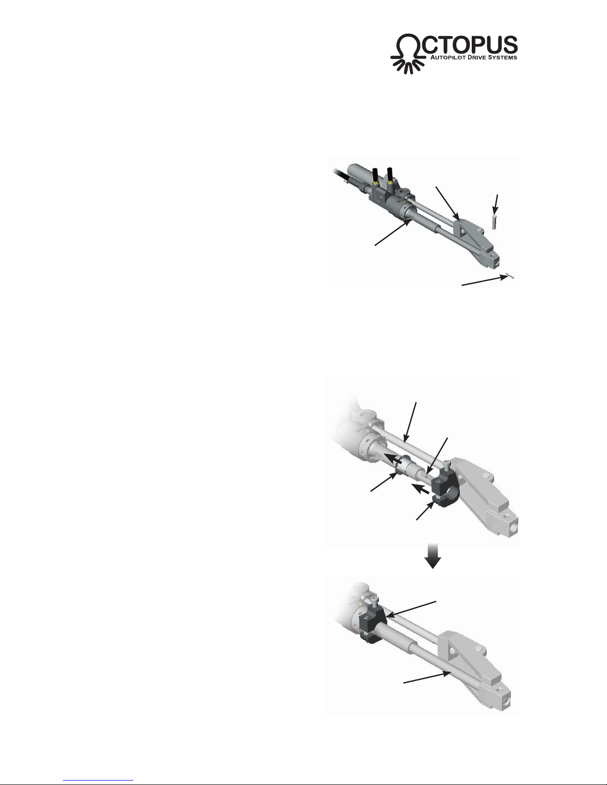
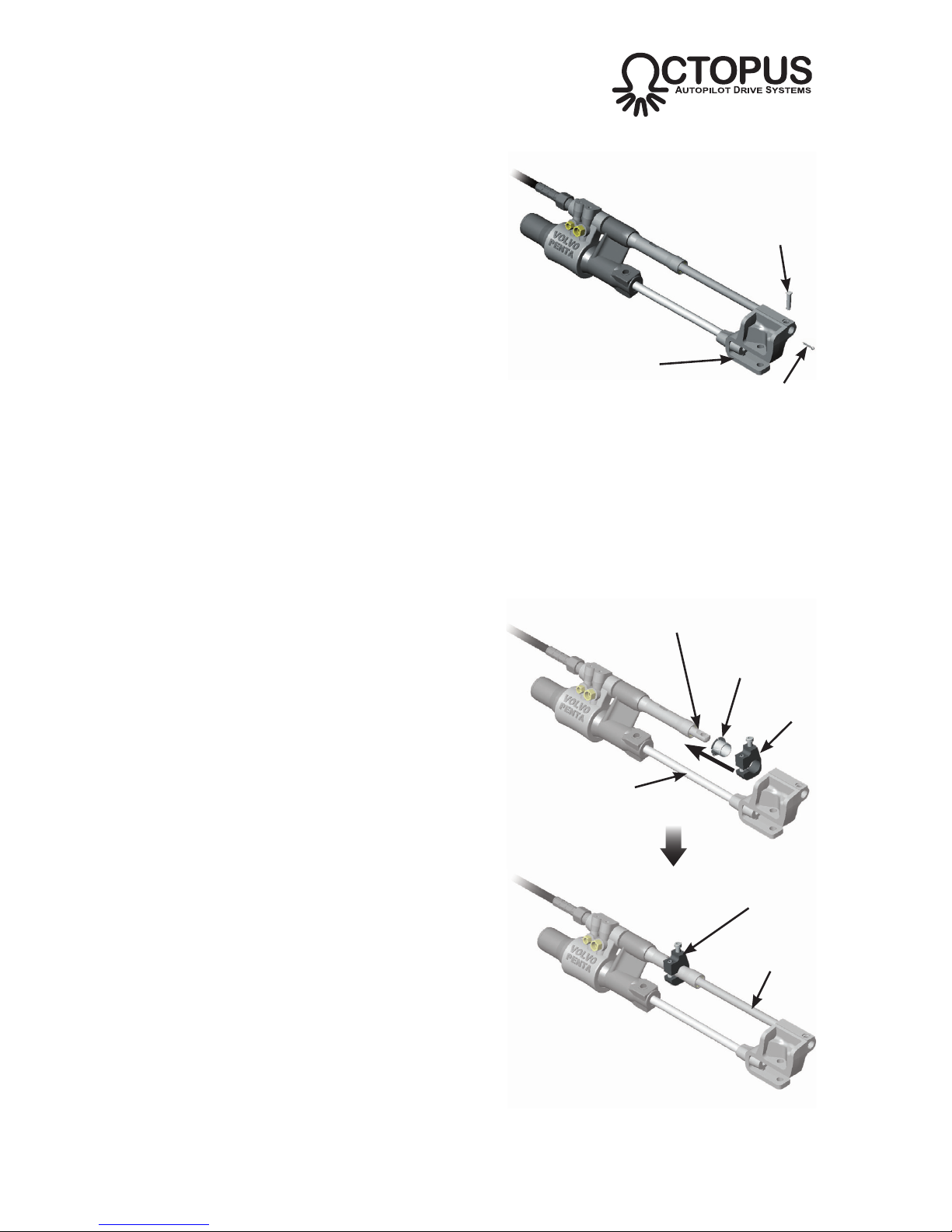
B3c Installation
• Prepare the steering cylinder
i) Use the helm to extend the steering
cylinder to full hard over as shown in
Fig B13 (it may be necessary to run
the engine to do this).
ii) Remove the cotter and clevis pins that
connect the primary steering cable
rod end to the steering cylinder clevis
bracket.
iii) Ensure that the flats on the steering
cylinder are vertically aligned (it may
be necessary to crack the nut on the
primary steering cable to adjust this,
the nut should then be re-torqued to
175in-lb / 20Nm).
• Fit the drive collar and spacer bush
i) Use the helm to retract the primary
steering cable to full opposite hard
over so the rod end disengages from
the cylinder clevis bracket (Fig B14a).
ii) Slacken the clamp screw and lock nut
on the fitting kit drive collar.
iii) Fit the spacer bush on to the steering
cylinder sleeve, ensure it is correctly
oriented - refer to Fig B14b.
iv) Slide the drive collar on to the steering
cylinder and over the spacer bush as
shown in the diagram. Do not tighten
the clamp screw at this stage.
v) Use the helm to extend the primary
steering cable back to full hard over
so that the rod end re-engages into
the cylinder clevis bracket.
13 of 44
Subject to change without notice OC15269 REV F
WWW.OCTOPUSDRIVES.COM
WWW.OCTOPUSEUROPE.COM
Fig B13 - Steering cylinder in fully extended posi-
tion
Clevis
bracket
Clevis
pin
Flat must
be vertical
Cotter pin
Steering cylinder
fully extended
Steering cable fully
retracted
Spacer
bush
Drive collar
Drive collar &
Spacer bush
Steering cable
fully extended
Fig B14 - Fitting the drive collar and bush to the
steering cable sleeve
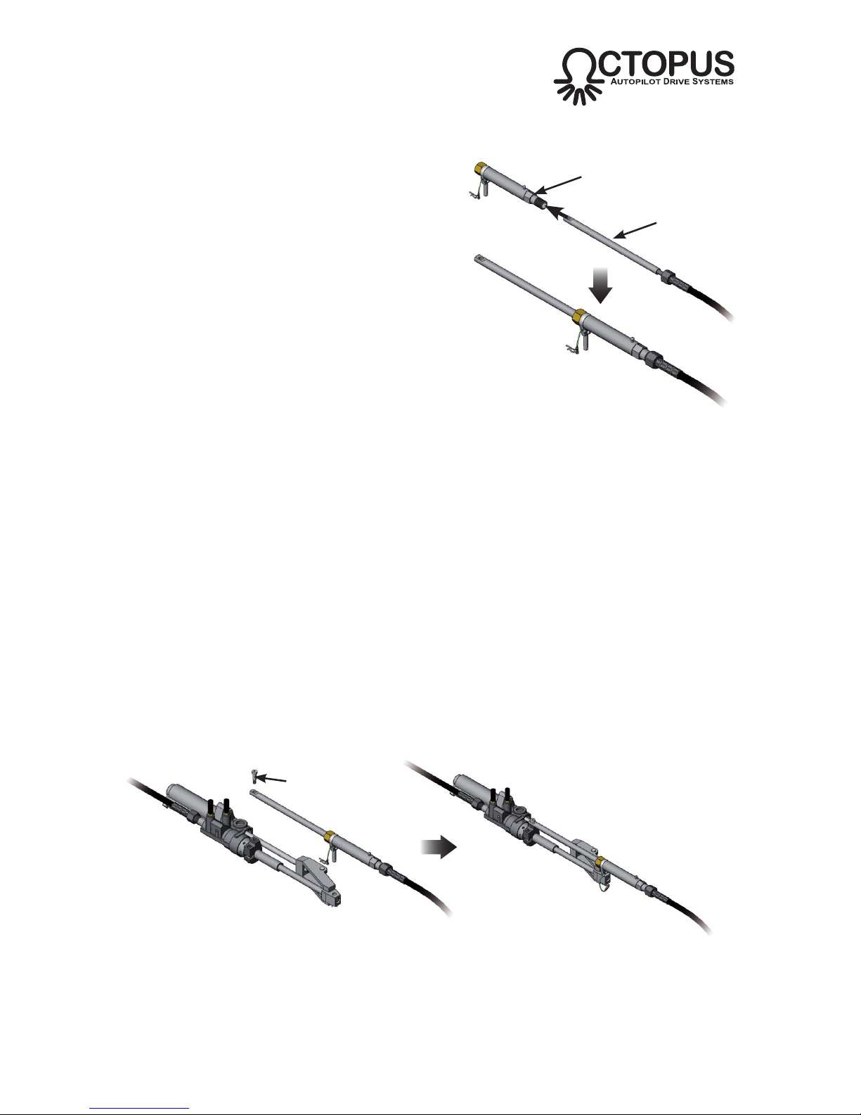
• Pre-fit the secondary steering cable to the guide tube/yoke assembly
i) Both the cable nut, the guide tube
thread and the inside of the guide
tube should be liberally lubricated with
marine quality grease before assembly.
ii) Insert the rod end of the secondary
steering cable into the threaded end of
the guide tube (Fig B15).
iii) Hand tighten the cable nut and torque
to 175in-lb (20Nm)*. Note that the
nut has an internal locking thread
which increases the amount of torque
required initially as the thread is cut.
* There should be NO movement between the
outer cable jacket and the guide tube when the nut
is fully tightened.
• Mount the connection kit and secondary steering cable to the steering cylinder.
This stage of the assembly will be easier if the Type R drive unit is not connected to the
secondary steering cable at this point, as fine adjustments to the drive collar positioning
are necessary and the backdrive friction from the drive unit will make this more difficult.
Connecting the drive unit should be the final stage of the mechanical assembly.
i) Remove the shoulder screw from the drive collar.
ii) Position the connection kit assembly above the steering cylinder and engage
onto the steering cylinder clevis bracket and drive collar as shown (Fig B16).
Ensure that the clevis pin is also locking the primary steering cable rod end
into the clevis bracket*. Lock in place using the hitch pin.
* If the clevis pin does not engage due to misalignment, adjust the manual steering helm slightly until
the hole in the primary steering cable rod end aligns with the holes in the clevis bracket.
14 of 44
Subject to change without notice OC15269 REV F
WWW.OCTOPUSDRIVES.COM
WWW.OCTOPUSEUROPE.COM
Guide tube/
yoke assembly
Fig B15 - Fitting the secondary
steering cable to the guide tube
Secondary
steering cable
iii) Adjust the position of the drive collar so that the shoulder screw hole aligns
with the hole in the secondary steering cable rod end.
iv) Fit the shoulder screw, torque to 55in-lb (6nm). The screw has a locking thread
which increases the amount of torque required initially as the thread is cut.
Fig B16 - Fitting connection kit to steering cylinder
Shoulder screw
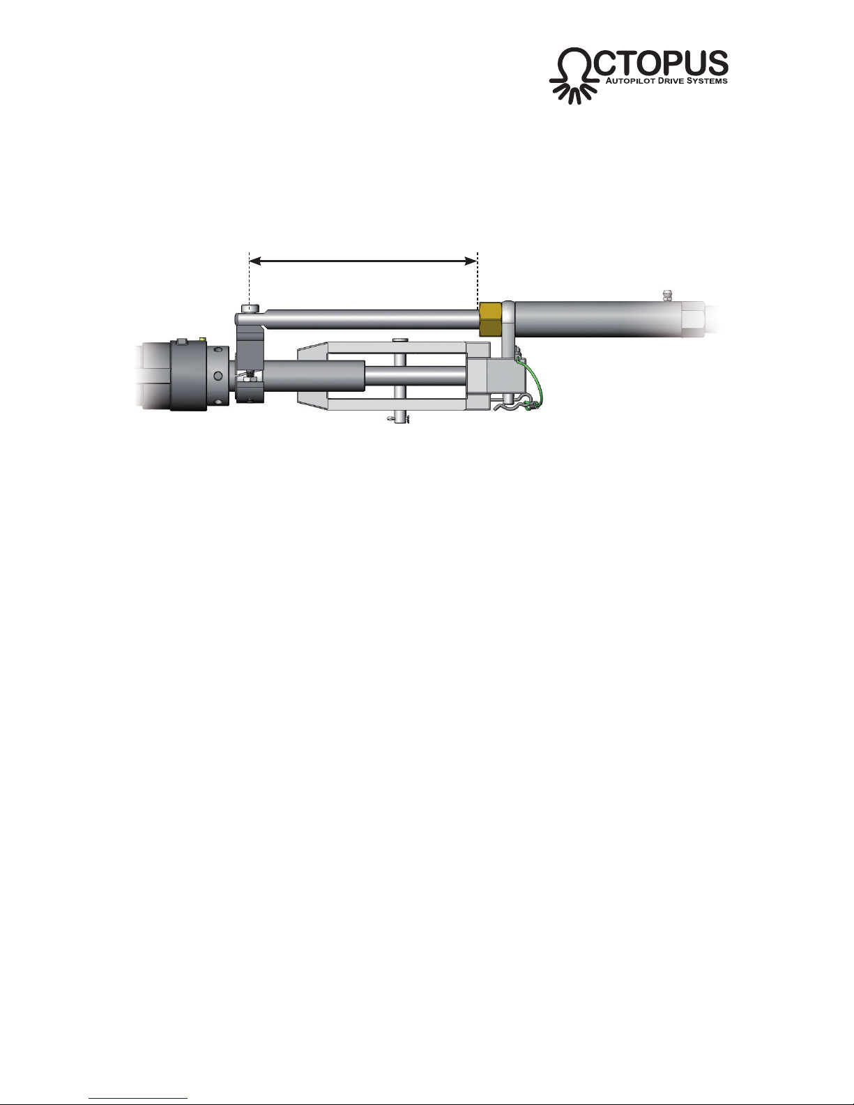
v) Use the manual helm to set the steering to the midstroke position. Adjust the
position of the drive collar so that there is a 7.4in (188mm) gap between it
and the front face of the steering cylinder (Fig B17). Tighten the drive collar
clamp screw and torque to 175in-lb (19Nm). Tighten the drive collar lock nut
and torque to 45in-lb (5nm).
15 of 44
Subject to change without notice OC15269 REV F
WWW.OCTOPUSDRIVES.COM
WWW.OCTOPUSEUROPE.COM
Fig B17 - Positioning the drive collar
7.4in (188mm)
when steering is centered
• Refer to section B9 on connecting the steering cable to the drive unit
16 of 44
Subject to change without notice OC15269 REV F
WWW.OCTOPUSDRIVES.COM
WWW.OCTOPUSEUROPE.COM
Primary
steering cable
Fig B12 - Mercruiser DHB 1994+ cylinder installation configuration
Secondary
steering cable
Octopus sterndrive
installation kit
Volvo steering cylinder
(model 3860883 shown)
Octopus Type R
drive unit
B4 Sterndrive Boats Volvo Gasoline & Diesel USA 1997 Onwards
The Octopus MDRESYS-A Type R Sterndrive pack can be fitted to mechanical
push-pull cable controlled sterndrive power assisted steering cylinders made by
Volvo for Gasoline engines and also Diesel engines in the USA since 1997.
The installation kit allows the second steering cable for the Type R drive to be fitted
to the sterndrive steering system.
B4a Engine compatibility
The installation kit supplied is compatible with Volvo 3860883, 3860726, 3862210,
3862513, 3860882, 3862456 and 3862514 steering cylinders.
B4b Supplied Parts
Type R Remote Rotary Autopilot Drive Unit
OC15SUK12B Sterndrive Installation Kit
OC15109-6 6ft (1.8m) Secondary Steering Cable*
OC15109-9 9ft (2.75m) Secondary Steering Cable*
* Recommended for twin engine installations.
17 of 44
Subject to change without notice OC15269 REV F
WWW.OCTOPUSDRIVES.COM
WWW.OCTOPUSEUROPE.COM
B4c Installation
• Prepare the steering cylinder
i) Use the helm to extend the steering
cylinder to full hard over as shown in
Fig B19 (it may be necessary to run
the engine to do this).
ii) Remove the cotter and clevis pins that
connect the primary steering cable
rod end to the steering cylinder clevis
bracket.
• Fit the drive collar and spacer bush
i) Use the helm to retract the primary
steering cable to full opposite hard
over so the rod end disengages from
the cylinder clevis bracket (Fig B20a).
ii) Slacken the clamp screw and lock nut
on the fitting kit drive collar.
iii) Fit the spacer bush* on to the steering
cylinder sleeve, ensure it is correctly
oriented - refer to Fig B20b.
* The spacer bush is not required on Volvo
models 3862513 and 3862514 which were fitted
from Sept 2003 onwards - the drive collar will clamp
directly onto the cable guide tube.
iv) Slide the drive collar on to the steering
cylinder and over the spacer bush as
shown in the diagram. Do not tighten
the clamp screw at this stage.
v) Use the helm to extend the primary
steering cable back to full hard over
so that the rod end re-engages into
the cylinder clevis bracket.
Fig B19 - Steering cylinder in fully extended
position
Clevis
bracket
Clevis
pin
Cotter pin
Steering cylinder
fully extended
Steering cable fully
retracted
Spacer
bush*
Drive
collar
Drive collar &
Spacer bush*
Steering cable fully
extended
Fig B20 - Fitting the drive collar and bush to the
steering cable sleeve
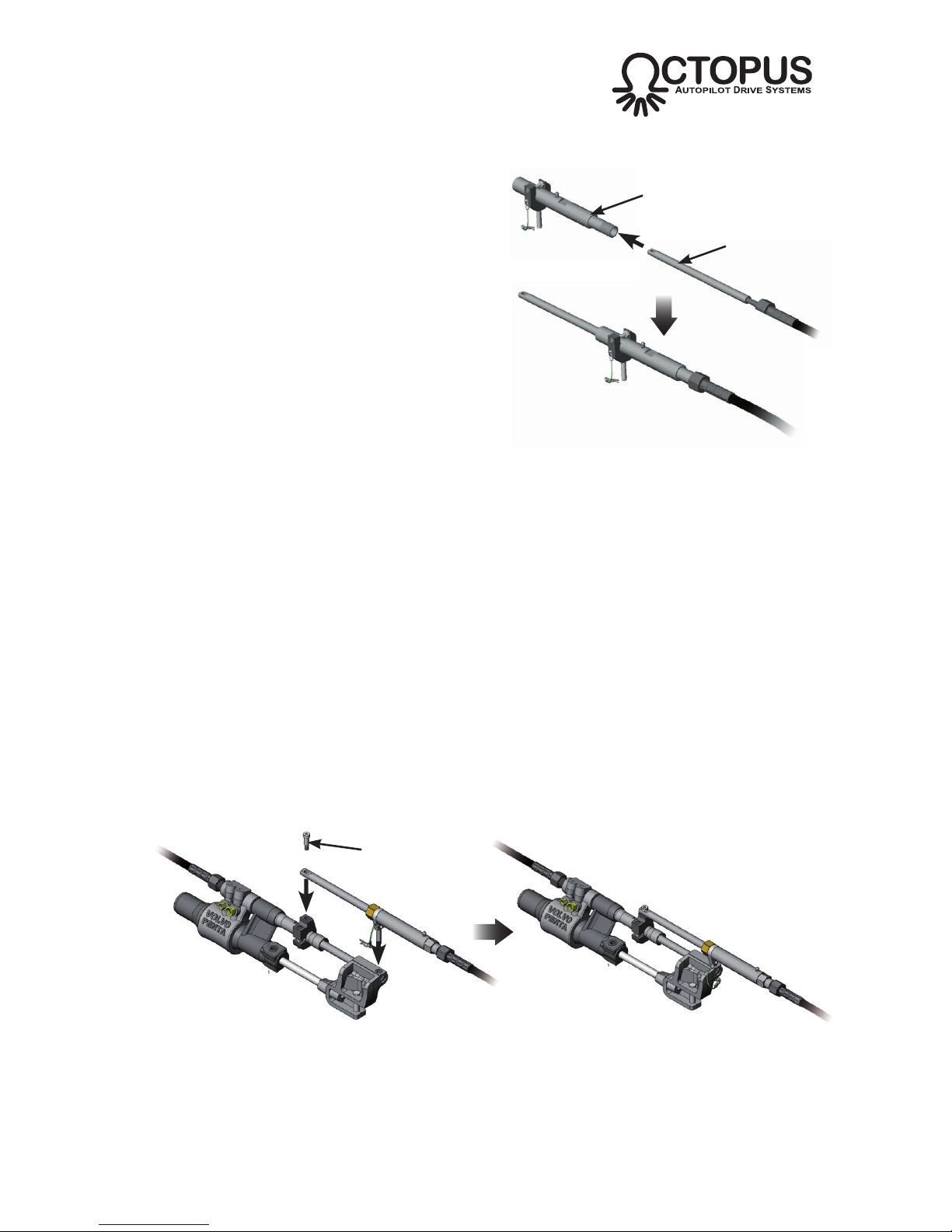
Fig B22 - Fitting connection kit to steering cylinder
Shoulder screw
18 of 44
Subject to change without notice OC15269 REV F
WWW.OCTOPUSDRIVES.COM
WWW.OCTOPUSEUROPE.COM
• Pre-fit the secondary steering cable to the guide tube/yoke assembly
i) Both the cable nut, the guide tube
thread and the inside of the guide
tube should be liberally lubricated with
marine quality grease before assembly.
ii) Insert the rod end of the secondary
steering cable into the threaded end of
the guide tube (Fig B21).
iii) Hand tighten the cable nut and torque
to 175in-lb (20Nm)*. Note that the
nut has an internal locking thread
which increases the amount of torque
required initially as the thread is cut.
* There should be NO movement between the
outer cable jacket and the guide tube when the nut
is fully tightened.
• Mount the connection kit and secondary steering cable to the steering cylinder.
This stage of the assembly will be easier if the Type R drive unit is not connected to the
secondary steering cable at this point, as fine adjustments to the drive collar positioning
are necessary and the backdrive friction from the drive unit will make this more difficult.
Connecting the drive unit should be the final stage of the mechanical assembly.
i) Remove the shoulder screw from the drive collar.
ii) Position the connection kit assembly above the steering cylinder and engage
onto the steering cylinder clevis bracket and drive collar as shown (Fig B22).
Ensure that the clevis pin is also locking the primary steering cable rod end
into the clevis bracket*. Lock in place using the hitch pin.
* If the clevis pin does not engage due to misalignment, adjust the manual steering helm slightly until
the hole in the primary steering cable rod end aligns with the holes in the clevis bracket.
Guide tube/
yoke assembly
Fig B21 - Fitting the secondary
steering cable to the guide tube
Secondary
steering cable
iii) Adjust the position of the drive collar so that the shoulder screw hole aligns
with the hole in the secondary steering cable rod end.
iv) Fit the shoulder screw, torque to 55in-lb (6nm). The screw has a locking thread
which increases the amount of torque required initially as the thread is cut.

19 of 44
Subject to change without notice OC15269 REV F
WWW.OCTOPUSDRIVES.COM
WWW.OCTOPUSEUROPE.COM
v) Use the manual helm to set the steering to the midstroke position. Adjust the
position of the drive collar so that there is a 7.3in (185mm) gap between it
and the front face of the steering cylinder (Fig B23). Tighten the drive collar
clamp screw and torque to 175in-lb (19Nm). Tighten the drive collar lock nut
and torque to 45in-lb (5nm).
Fig B23 - Positioning the drive collar
Guide Tube*
7.3in (185mm)
when steering is centered
* This diagram shows the earlier model Volvo cylinders, which featured a “necked” guide tube -
later models have a simpler parallel guide tube, which does not require the use of the Drive Collar
Spacer Bush.
• Refer to section B9 on connecting the secondary steering cable to the drive unit.

20 of 44
Subject to change without notice OC15269 REV F
WWW.OCTOPUSDRIVES.COM
WWW.OCTOPUSEUROPE.COM
Primary
steering cable
Fig B24 - Mercruiser Saginaw 1983-93 cylinder installation configuration
Secondary
steering cable
Octopus sterndrive
installation kit
Mercruiser Saginaw
steering cylinder
Octopus Type R
drive unit
B5 Sterndrive Boats Mercruiser Saginaw 1983-93
The Octopus MDRESYS-B Type R Sterndrive pack can be fitted to mechanical
push-pull cable controlled sterndrive power assisted steering cylinders fitted to
Mercruiser Alpha One Generation II and Bravo Sterndrives between 1983 and 1993
(Saginaw).
The installation kit allows the second steering cable for the Type R drive to be fitted
to the sterndrive steering system.
B5a Engine compatibility
Mercruiser Saginaw steering cylinders are fitted to Alpha One Generation II and
Bravo Sterndrives from 1983 to 1993.
B5b Supplied Parts
Type R Remote Rotary Autopilot Drive Unit
OC15SUK12C Sterndrive Installation Kit
OC15109-6 6ft (1.8m) Secondary Steering Cable*
* Other lengths are available as optional accessories

21 of 44
Subject to change without notice OC15269 REV F
WWW.OCTOPUSDRIVES.COM
WWW.OCTOPUSEUROPE.COM
B5c Installation
• Prepare the steering cylinder
i) Use manual helm to set the steering
cylinder to the mid stroke position as
shown in Fig B25 (it may be neces-
sary to run the engine to do this).
ii) Remove the cotter and clevis pins
that connect the primary steering
cable rod end to the steering
cylinder clevis bracket.
• Fit the secondary steering cable to the guide tube
i) The cable nut, guide tube thread
and inside of the guide tube should
be liberally lubricated with marine
quality grease before assembly.
ii) Insert the rod end of the secondary
steering cable into the threaded
end of the guide tube (Fig B26).
iii) Hand tighten the cable nut and
torque to 175in-lb (20Nm)*. Note
that the nut has an internal locking
thread which increases the amount
of torque required initially as the
thread is cut.
* There should be NO movement between
the outer cable jacket and the guide tube
when the nut is fully tightened.
• Fit the two clamp assemblies to the guide
tube and cable assembly
i) The anti-vibration washers must
be fitted in the correct order on the
clamp assemblies, with the serrated
face of the washer in contact with
the nut face and the clamp face. The
cam face of the washers must be in
contact with each other (Fig B27).
iv) Slacken the nuts enough so that the
clamps can slide over the guide tube.
Locate the clamps in the GREEN
color coded slots as shown. Do not
tighten the nuts at this stage.
Fig B25 - Steering cylinder in mid stroke position
Clevis
bracket
Clevis
pin
Cotter pin
Guide tube
Fig B27 - Fitting the clamp assemblies
Secondary
steering cable
Fig B26 - Fitting the secondary steering cable
to the guide tube
Serrated faces
Cam faces

22 of 44
Subject to change without notice OC15269 REV F
WWW.OCTOPUSDRIVES.COM
WWW.OCTOPUSEUROPE.COM
• Fit the clevis block to the secondary steering cable rod end
i) Remove the hitch pin from the clevis
block pin.
ii) Remove the nut, 2 x anti-vibration
washers and bolt from the clevis block.
ii) Insert the cable rod end into the slotted
hole in the clevis block. Ensure the
clevis block is correctly oriented as
shown, with the clevis pin pointing
down (Fig B28).
iv) Fit the bolt through the bottom of the
clevis block, through the cable rod end
and out the top of the block. Fit the
anti-vibration washers in the correct
order, with the serrated face of the
washer in contact with the the nut face
and the clevis block face. The cam
face of the washers must be in contact
with each other.
v) Tighten the locking nut and torque to
180-200in-lb (20-22.5Nm). The screw
has a locking thread which increases
the amount of torque required initially
as the thread is cut.
Clevis
block
Fig B28 - Fitting the clevis block to the
secondary cable rod end
Hitch
pin
Serrated
faces
Cam
faces
Rod
end

23 of 44
Subject to change without notice OC15269 REV F
WWW.OCTOPUSDRIVES.COM
WWW.OCTOPUSEUROPE.COM
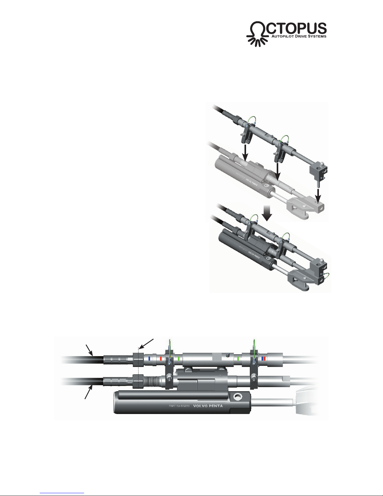
• Mount the connection kit and secondary steering cable to the steering cylinder.
This stage of the assembly will be easier if the Type R drive unit is not connected to the
secondary steering cable at this point, as fine adjustments to the drive collar positioning
are necessary and the backdrive friction from the drive unit will make this more difficult.
Connecting the drive unit should be the final stage of the mechanical assembly.
i) Position the connection kit assembly
above the steering cylinder as shown
(Fig B29). Hold the two clamp assem-
blies open so they will fit over the
manual steering cable guide tube, at
the same time ensure that both clamps
remain engaged in the GREEN color
coded slots of the secondary cable
guide tube.
ii) Lower the connection kit assembly
onto the cylinder and clevis bracket as
shown. Ensure that the clevis pin is
also locking the primary steering cable
rod end into the clevis bracket*. Lock
in place using the hitch pin.
* If the clevis pin does not engage due to misalign-
ment, adjust the manual steering helm slightly
until the hole in the primary steering cable rod end
aligns with the holes in the clevis bracket.
iii) Position the connection kit so that there is a minimal gap between the rear
clamp assembly and the primary steering cable guide tube lock nut (Fig B30).
Tighten the nuts on both clamp assemblies and torque to 100in-lb (11nm).
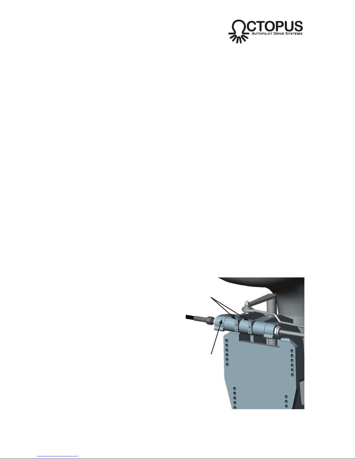
Fig B30 - Positioning the connection kit
Front clamp
assembly
Rear clamp
assembly
• Refer to section B9 on connecting the secondary steering cable to the drive unit.
Fig B29 - Fitting connection kit to steering
cylinder
Guide tube
lock nut
Minimal
gap

24 of 44
Subject to change without notice OC15269 REV F
WWW.OCTOPUSDRIVES.COM
WWW.OCTOPUSEUROPE.COM
Primary
steering cable
Fig B31 - Volvo Diesel (Europe) cylinder installation configuration
Secondary
steering cable
Octopus sterndrive
installation kit
Volvo 872215
steering cylinder
Octopus Type R
drive unit
B6 Sterndrive Boats Volvo Diesel Europe
The Octopus MDRESYS-B Type R Sterndrive pack can be fitted to mechanical
push-pull cable controlled sterndrive power assisted steering cylinders made by
Volvo for Diesel engines in Europe.
The installation kit allows the second steering cable for the Type R drive to be fitted
to the sterndrive steering system.
B6a Engine compatibility
Volvo Diesel engines fitted with model 872215 sterndrive power assisted steering
cylinders.
B6b Supplied Parts
Type R Remote Rotary Autopilot Drive Unit
OC15SUK12C Sterndrive Installation Kit
OC15109-6 6ft (1.8m) Secondary Steering Cable*
* Other lengths are available as optional accessories

25 of 44
Subject to change without notice OC15269 REV F
WWW.OCTOPUSDRIVES.COM
WWW.OCTOPUSEUROPE.COM
B6c Installation
• Prepare the steering cylinder
i) Use manual helm to set the steering
cylinder to the mid stroke position as
shown in Fig B32 (it may be neces-
sary to run the engine to do this).
ii) Remove the cotter and clevis pins
that connect the primary steering
cable rod end to the steering
cylinder clevis bracket.
• Fit the secondary steering cable to the guide tube
i) The cable nut, guide tube thread
and inside of the guide tube should
be liberally lubricated with marine
quality grease before assembly.
ii) Insert the rod end of the secondary
steering cable into the threaded
end of the guide tube (Fig B33).
iii) Hand tighten the cable nut and
torque to 175in-lb (20Nm)*. Note
that the nut has an internal locking
thread which increases the amount
of torque required initially as the
thread is cut.
* There should be NO movement between
the outer cable jacket and the guide tube
when the nut is fully tightened.
• Fit the two clamp assemblies to the guide
tube and cable assembly
i) The anti-vibration washers must
be fitted in the correct order on the
clamp assemblies, with the serrated
face of the washer in contact with
the nut face and the clamp face. The
cam face of the washers must be in
contact with each other (Fig B34).
iv) Slacken the nuts enough so that the
clamps can slide over the guide tube.
Locate the clamps in the YELLOW
color coded slots as shown. Do not
tighten the nuts at this stage.
Fig B32 - Steering cylinder in mid stroke position
Clevis
bracket
Clevis
pin
Cotter pin
Guide tube
Fig B34 - Fitting the clamp assemblies
Secondary
steering cable
Fig B33 - Fitting the secondary steering cable
to the guide tube
Serrated faces
Cam faces
26 of 44
Subject to change without notice OC15269 REV F
WWW.OCTOPUSDRIVES.COM
WWW.OCTOPUSEUROPE.COM
• Fit the clevis block to the secondary steering cable rod end
i) Remove the hitch pin from the clevis
block pin.
ii) Remove the nut, 2 x anti-vibration
washers and bolt from the clevis block.
ii) Insert the cable rod end into the slotted
hole in the clevis block. Ensure the
clevis block is correctly oriented as
shown, with the clevis pin pointing
down (Fig B35).
iv) Fit the bolt through the bottom of the
clevis block, through the cable rod end
and out the top of the block. Fit the
anti-vibration washers in the correct
order, with the serrated face of the
washer in contact with the the nut face
and the clevis block face. The cam
face of the washers must be in contact
with each other.
v) Tighten the locking nut and torque to
180-200in-lb (20-22.5Nm). The screw
has a locking thread which increases
the amount of torque required initially
as the thread is cut.
Clevis
block
Fig B35 - Fitting the clevis block to the
secondary cable rod end
Hitch
pin
Serrated
faces
Cam
faces
Rod
end
27 of 44
Subject to change without notice OC15269 REV F
WWW.OCTOPUSDRIVES.COM
WWW.OCTOPUSEUROPE.COM
• Mount the connection kit and secondary steering cable to the steering cylinder.
This stage of the assembly will be easier if the Type R drive unit is not connected to the
secondary steering cable at this point, as fine adjustments to the drive collar positioning
are necessary and the backdrive friction from the drive unit will make this more difficult.
Connecting the drive unit should be the final stage of the mechanical assembly.
i) Position the connection kit assembly
above the steering cylinder as shown
(Fig B36). Hold the two clamp assem-
blies open so they will fit over the
manual steering cable guide tube, at
the same time ensure that both clamps
remain engaged in the YELLOW color
coded slots of the secondary cable
guide tube.
ii) Lower the connection kit assembly
onto the cylinder and clevis bracket as
shown. Ensure that the clevis pin is
also locking the primary steering cable
rod end into the clevis bracket*. Lock in
place using the hitch pin.
* If the clevis pin does not engage due to misalign-
ment, adjust the manual steering helm slightly
until the hole in the primary steering cable rod end
aligns with the holes in the clevis bracket.
iii) Position the connection kit so that the
primary and secondary steering cable
nuts are aligned (Fig B38). Tighten the
nuts on both clamp assemblies and
torque to 100in-lb (11nm).
Fig B37 - Positioning the connection kit
Align nuts
Secondary steering
cable
Primary
steering cable
• Refer to section B9 on connecting the secondary steering cable to the drive unit.
Fig B36 - Fitting connection kit to steering
cylinder

B7 Inboard Engined Boats & Sailboats
The Universal Inboard Installation Kit can be fitted to mechanically steered inboard
engined boats with access to a quadrant or tiller or smaller sailboats. It is recommended for use on vessels with a maximum speed of 44 mph.
The installation kit allows the second steering cable for the Type R drive to be fitted
to the boat’s steering quadrant or tiller.
B7a Compatibility
The MDRESYS-E kit is suitable for use on most sailboats and power boats with
mechanical steering less than 32ft (9.75m) in length and with a displacement of not
more than 13,200lbs (6,000Kg).
In all cases, the primary steering system must be capable of being back-driven with
a torque of less than 105in-lb (12Nm). If the amount of force required to maintain
course is greater than this, then the Type R drive is not suitable.
B7b Supplied Parts
Type R Remote Rotary Autopilot Drive Unit
OC15SUK19 Universal Inboard Installation Kit
OC15109-6 6ft (1.8m) Secondary Steering Cable
OC15109-9 9ft (2.75m) Secondary Steering Cable*
* Recommended for twin engine/rudder installations.
28 of 44
Subject to change without notice OC15269 REV F
WWW.OCTOPUSDRIVES.COM
WWW.OCTOPUSEUROPE.COM
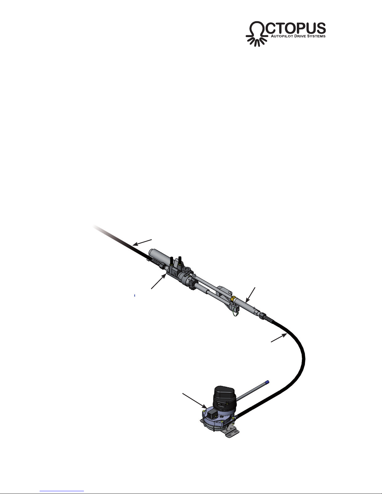
Fig B38 - Inboard installation configuration
Steering cable
Octopus universal
installation kit
Steering
tiller/quadrant
Octopus Type R
drive unit
Quick release
clevis bracket
B7c Installation
• Determine the mounting position of the installation kit (Fig B39)
This stage of the assembly will be easier if the Type R drive unit is not connected to the
secondary steering cable at this point, as fine adjustments to the drive collar positioning
are necessary and the backdrive friction from the drive unit will make this more difficult.
Connecting the drive unit should be the final stage of the mechanical assembly.
i) The kit must be mounted to a secure and stable surface that will be able to
withstand the forces generated by the drive and the rudder.
ii)
The kit has an 8.5in (216mm) stroke
and will need to be located so that the
rudder is at a 35º angle when in the
hard over position. This means the
steering cable attachment point will
typically be approx 7.4in (188mm) from
the rudder stock. Any further from the
rudder stock will reduce the amount
of rudder angle which the drive can
apply, which may adversely affect
the responsiveness of the autopilot.
Moving the mounting point closer
to the rudder stock will increase the
amount of force required to move the
rudder which may slow the lock-to-lock
time of the autopilot.
iii) The kit features a universal hub which offers 360º freedom of movement in
the horizontal plane and ±40º in the vertical plane. It can be mounted in any
orientation provided the kit is not forced beyond its rotational limits at any
point across the full steering range of the boat.
iv) The threaded guide tube offers up to ±3in (75mm) of lateral adjustment.
v) Ideally, the kit should be located so that the thrust from the steering cable is
perpendicular (ie at 90º) to the tiller at the mid-stroke position.
vi) The kit can be mounted with or without the base plate supplied.
vii) The clevis bracket can be mounted directly to the quadrant, or to a separate
tiller arm. An 0.375in (9.5mm) diameter hole will need to be drilled through
the tiller in order to attach the shoulder bolt supplied with the clevis bracket.
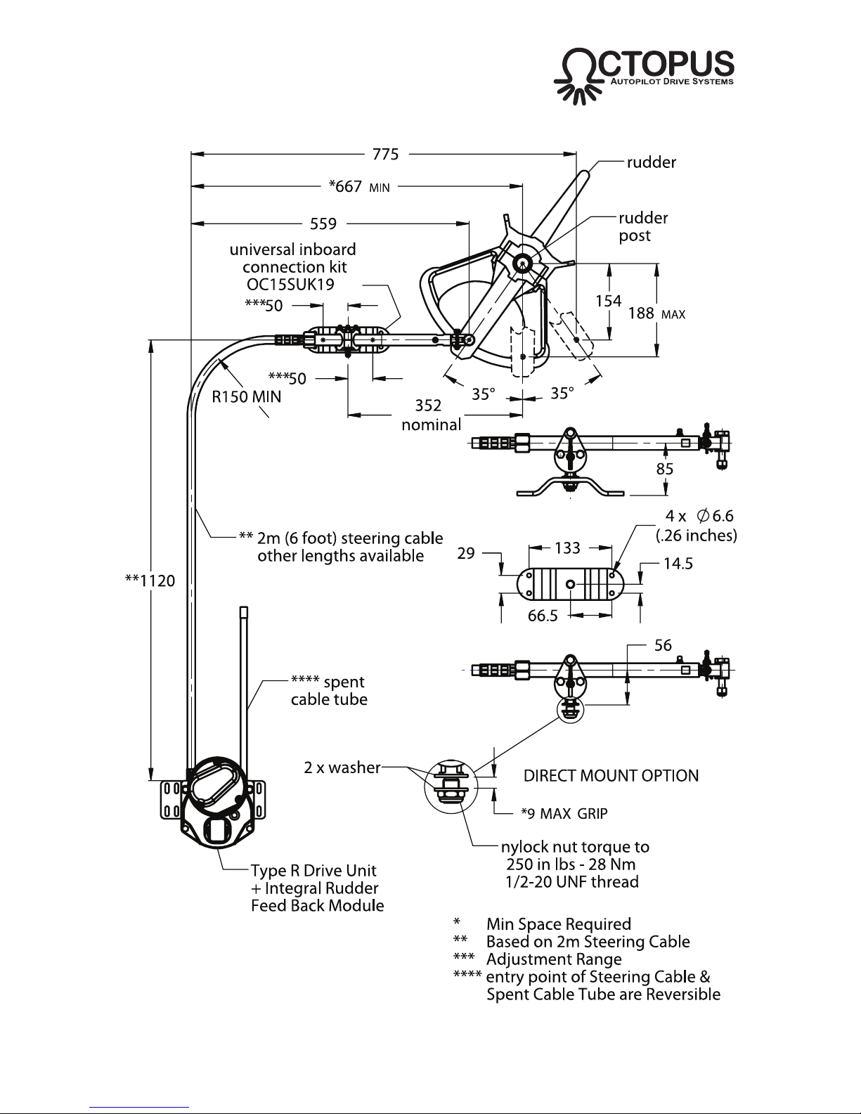
viii)Refer to the installation envelope diagram (Fig B40 overleaf) to ascertain the
best position for the kit.
29 of 44
Subject to change without notice OC15269 REV F
WWW.OCTOPUSDRIVES.COM
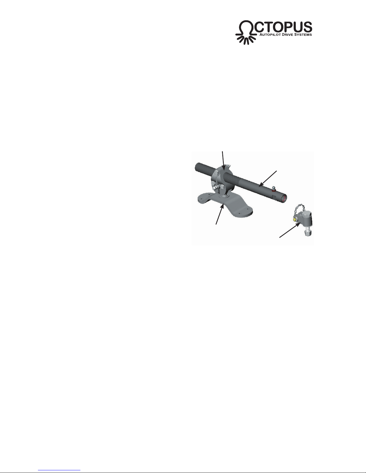
WWW.OCTOPUSEUROPE.COM
Universal hub
Threaded guide tube with
±3in (75mm) of adjustment
Clevis
bracket
Baseplate
Fig B39 - Universal installation kit
30 of 44
Subject to change without notice OC15269 REV F
WWW.OCTOPUSDRIVES.COM
WWW.OCTOPUSEUROPE.COM
Fig B40 - Inboard kit installation envelope
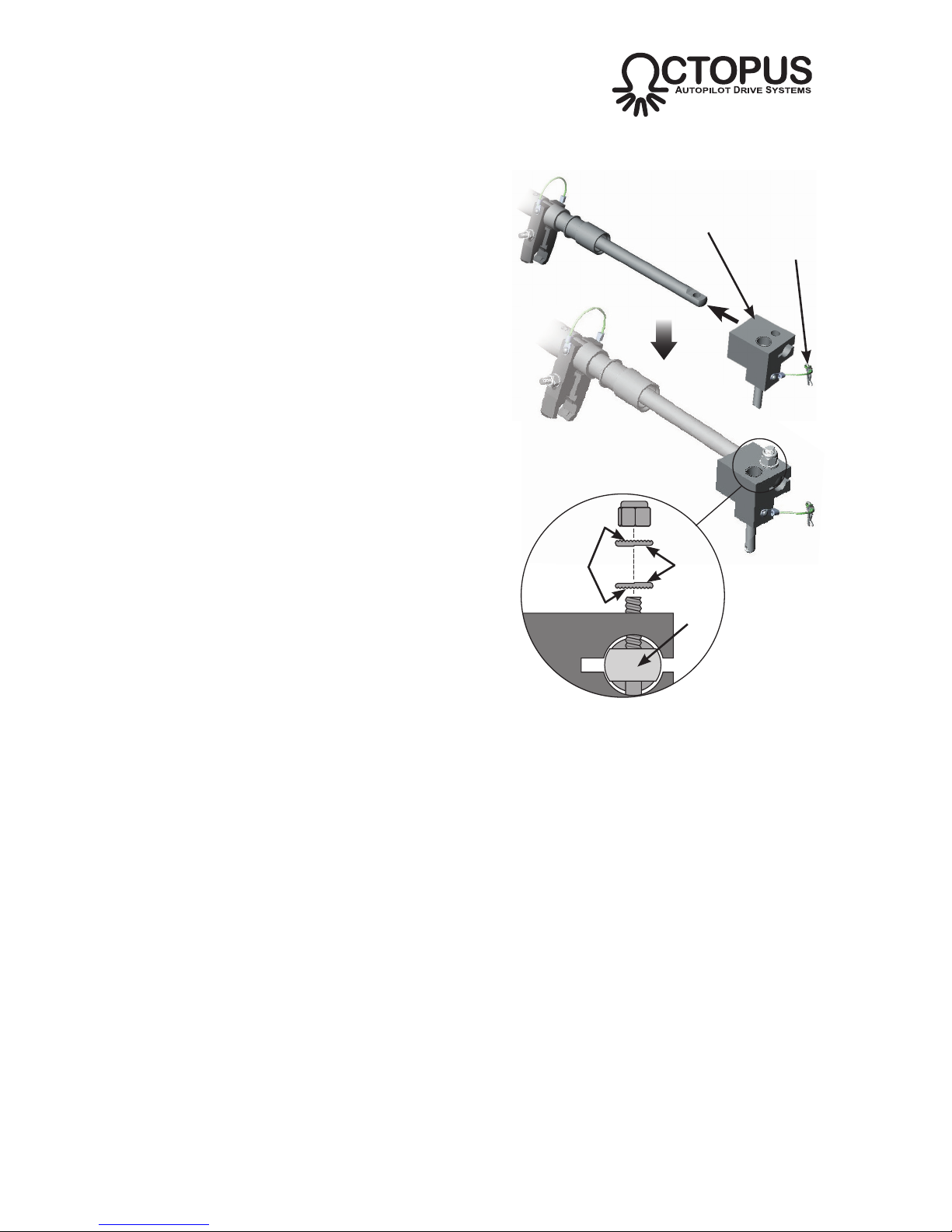
• Fit the clevis bracket to the tiller/quadrant
i) Use manual helm to set the rudder to
the centerline position.
ii) Using the information from the
installation envelope diagram, drill
an 0.375in (9.5mm) diameter hole
through the tiller/quadrant at a
distance of 6in (152mm) from the
rudder stock*.
* The clevis bracket can be mounted to a
separate tiller arm if a suitable location is not
available on the tiller/quadrant
ii) Fit the clevis bracket to the tiller as
shown in Fig B41, ensuring that the
plastic bushes, bracket, washer etc
are fitted in the correct order.
iii) Tighten the locking nut and torque to
180-200in-lb (20-22.5Nm). The screw
has a locking thread which increases
the amount of torque required initially
as the thread is cut.
iv) Remove the quick release locking pin
from the bracket.
• Fit the steering cable to the guide tube
i) The cable nut, guide tube thread and
inside of the guide tube should be
liberally lubricated with marine quality
grease before assembly.
ii) Insert the rod end of the steering
cable into the threaded end of the
guide tube (Fig B42).
iii) Hand tighten the cable nut and
torque to 175in-lb (20Nm)*. Note that
the nut has an internal locking thread
which increases the amount of torque
required initially as the thread is cut.
* There should be NO movement between the
outer cable jacket and the guide tube when the
nut is fully tightened.
31 of 44
Subject to change without notice OC15269 REV F
WWW.OCTOPUSDRIVES.COM
WWW.OCTOPUSEUROPE.COM
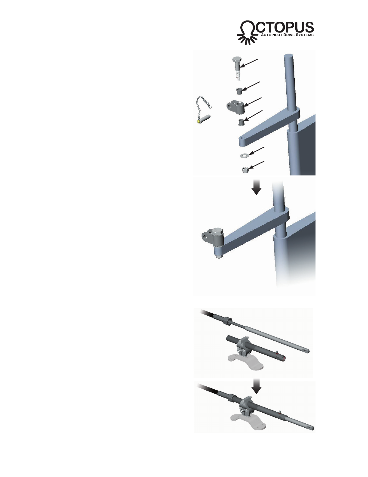
Shoulder
bolt
Bush
Bush
Clevis
bracket
Washer
Locknut
Fig B41 - Fitting the clevis bracket to the tiller
Fig B42 - Fitting the steering cable to the
drive tube

• Attach the steering cable to the tiller
i) Rotate the steering cable rod end so
that the hole is horizontally aligned.
ii) Position the steering cable rod end
into the clevis bracket (Fig B43).
iii) Insert the quick release locking pin
and lock in place using the hitch pin.
• Refer to section B9 on connecting the secondary steering cable to the drive unit.
B7d Quick Release
In an emergency situation the steering cable can be quickly disconnected from the
tiller by pulling out the hitch pin and then removing the locking pin.
B7e Specification
Maximum stroke .......................................................... 8.5in (216mm)
Peak Thrust ................................................................. 330Ibs / 136kg
Max Rudder Torque..................................................... 185ft-lb (250Nm)
Hard Over Time ........................................................... 12-15 seconds
Peak Power ................................................................. 60 watts 5 amps
Average Power ............................................................ 1.25 amps
Tiller arm radius ........................................................... 7.5in /190mm
Max displacement ........................................................ 13,200Ibs / 6,000kg
Max boat length ........................................................... 32ft / 10m
Voltage......................................................................... 12V DC
Clutch circuit power ..................................................... 850mA
32 of 44
Subject to change without notice OC15269 REV F
WWW.OCTOPUSDRIVES.COM
WWW.OCTOPUSEUROPE.COM
Fig B43 - Attaching the steering cable to the tiller
Hitch pin
Quick release
locking pin

B8 Routing Steering Cable
When deciding on the routing path for the Type R drive steering cable, consideration
must be given to the following points:
i) There must be sufficient slack in the cable to allow for any movements of the
steering mechanism when steering from lock to lock - ensure that no part of
the cable is under stress at any point of steering, otherwise damage to the
cable may result over long term usage.
ii) The chosen route should use the minimum possible number of bends.
iii) If any bends are necessary, maximise the bend radius as much as possible.
It is recommended that bends have a radius of no less than 6in (150mm) and
that the combined total angle of all bends is no more than 270º.
B8a Cable Length Calculation
All Type R Drive System Packs are supplied as standard with a 6ft (1.8m) steering
cable, which should be suitable for most installations. If a suitable location for
mounting the drive unit is not available using this cable then other lengths are
available as separate accessories.
Use a length of rope or electrical cable to plan out the steering cable route and then
measure the total length required (Fig B44) :
(‘A’ Dimension + ‘B’ Dimension) – 4in for a 90º bend
Round up the result to the nearest full foot size and then refer to section D1 for the
appropriate custom cable order code.
33 of 44
Subject to change without notice OC15269 REV F
WWW.OCTOPUSDRIVES.COM
WWW.OCTOPUSEUROPE.COM
6in (150mm)
minimum radius
‘B’ Dimension
‘A’ Dimension
Midstroke
Fig B44 - Preferred cable routing

B9 Connecting Steering Cable To Drive
Either port can be use for the steering cable entry - select the most convenient for
the installation.
i) Remove the lock bolts, nuts and
washers from both ports (Fig B45).
ii) Insert the steering cable into the drive
port. Using moderate force, guide the
inner cable around the driving hub
and out of the opposite port.
iii) Push the steering cable jacket into
the port until the retaining collar butts
against the drive housing (Fig B46).
If required, the cable can be “driven”
into the drive by powering up the
clutch and drive.
iv) Insert the lock bolt to hold the cable in place.
v) If undue force is required to insert the cable, this may be caused by the end
of the inner cable fouling the outer face of the nylon guide. If this is the case,
remove the cable and inspect for sharp edges. If possible, twist the cable so
that the sharp edge is towards the inside of the radius, or use a file or burr
type tool to remove the sharp edges.
vi) Fit the spent cable tube to the opposite port and insert the lock bolt.
vii) Fit washers & nuts to both lock bolts, tighten & torque to 40-45in-lbs (4Nm).
34 of 44
Subject to change without notice OC15269 REV F
WWW.OCTOPUSDRIVES.COM
WWW.OCTOPUSEUROPE.COM
Fig B45 - Remove cable locking bolts
Steering cable
outer jacket
Retaining
collar
Spent
cable tube
Fig B46 - Fitting steering cable and spent cable tube

B10 Rudder Feedback Unit (RFB) Installation & Calibration
Most autopilots require a rudder feedback device which is usually attached directly
to the rudder - this complicates installation in certain applications, particularly with
sterndrive and outboard engined boats. They are often exposed to the elements
and prone to damage due to
their location.
The optional Rudder Feedback
Unit is a simple solution which
attaches directly to the drive unit
itself and is calibrated using a
simple procedure.
A range of Rudder Feedback
units are available which are
compatible with most popular
autopilot systems (Fig B47).
B10a Universal RFB Setup
If a dedicated RFB is not available for a brand of autopilot, the OC15SUK27
Universal RFB should be suitable. This module is configured to the particular
autopilot using DIP switch settings:
35 of 44
Subject to change without notice OC15269 REV F
WWW.OCTOPUSDRIVES.COM
WWW.OCTOPUSEUROPE.COM
ORDER CODE
AUTOPILOT
RESISTOR
OC15SUK27A COMNAV, SI-TEX
4k
OC15SUK27B RAYMARINE
5k
OC15SUK27D
SIMRAD 3k
OC15SUK27E
FURUNO, TMQ,
NAVMAN, GARMIN,
COURSEMASTER,
SI-TEX SP110
1k
Fig B47 - Rudder feedback compatibility
AUTOPILOT DIPSWITCH RESISTOR**
FURUNO, TMQ,
NAVMAN, GARMIN,
COURSEMASTER,
SI-TEX SP110
1k
RAYMARINE 5k
SIMRAD*
3k
COMNAV, SI-TEX 4k
* Simrad autopilots also require Signal Conversion Module OC15SUK83
** Fixed resistance measured between black and white wire. Resistance
between white and black wire is variable
DIP Switch
Fig B48 - Universal RFB DIP Switch Settings

36 of 44
Subject to change without notice OC15269 REV F
WWW.OCTOPUSDRIVES.COM
WWW.OCTOPUSEUROPE.COM
B10b Calibration and Installation
The calibration routine should be performed after the drive unit has been fitted to the
vessel and wired up to the autopilot. The RFB should also be electrically connected
to the autopilot prior to calibration (refer to sections C1 and C2).
i) Remove the RFB module from the drive
housing (if already fitted) by removing
the two fixing screws.
ii) Center the rudder of the boat using the
manual helm (you may need to run the
engine to do this).
iii) Calibrate the RFB by aligning the two
red paint marks on the underside of the
unit (Fig B49).
iv) Remove the RFB blanking cap from the
drive unit housing (Fig B50a).
v) Fit the RFB to the drive housing and fix using the two screws provided (Fig B50b).
Ensure that the RFB driven gear is correctly engaged with the drive gear before
tightening the 2 screws.
vi) Refer to the autopilot manufacturer’s installation guide for instructions on any
additional software controlled RFB fine calibration and hardover limitation.
Align the two
red dots
Fig B49 - Calibrating the rudder feedback unit
Blanking
cap
Fig B50 - Installing the rudder feedback unit

37 of 44
Subject to change without notice OC15269 REV F
WWW.OCTOPUSDRIVES.COM
WWW.OCTOPUSEUROPE.COM
B11 Interference Evaluation (Outboard Engines Only)
It is vital that an operating clearance check is performed between the second steering cable, outboard fitting kit and the existing hardware including hoses, electrical
cables and control cables before the system is connected to an autopilot system or
the boat is taken to sea. Two people will be required to carry out this evaluation.
i) While one person turns the steering wheel from full lock to full lock, the other
person should observe the outboard engine movement and ensure that there
is no physical interference between any parts across the full steering lock.
ii) With the outboard set to full lock left, tilt the engine to the full up position and
ensure that there is no physical interference between the parts at any stage.
Repeat this procedure with the outboard set to full lock right.
iii) It may be necessary to reroute hoses, electrical cables, control cables or
other hardware to avoid interference during operation. All hardware must be
well clear of the outboard fitting kit and second steering cable. Chafing may
occur if parts are permitted to come into contact.

38 of 44
Subject to change without notice OC15269 REV F
WWW.OCTOPUSDRIVES.COM
WWW.OCTOPUSEUROPE.COM
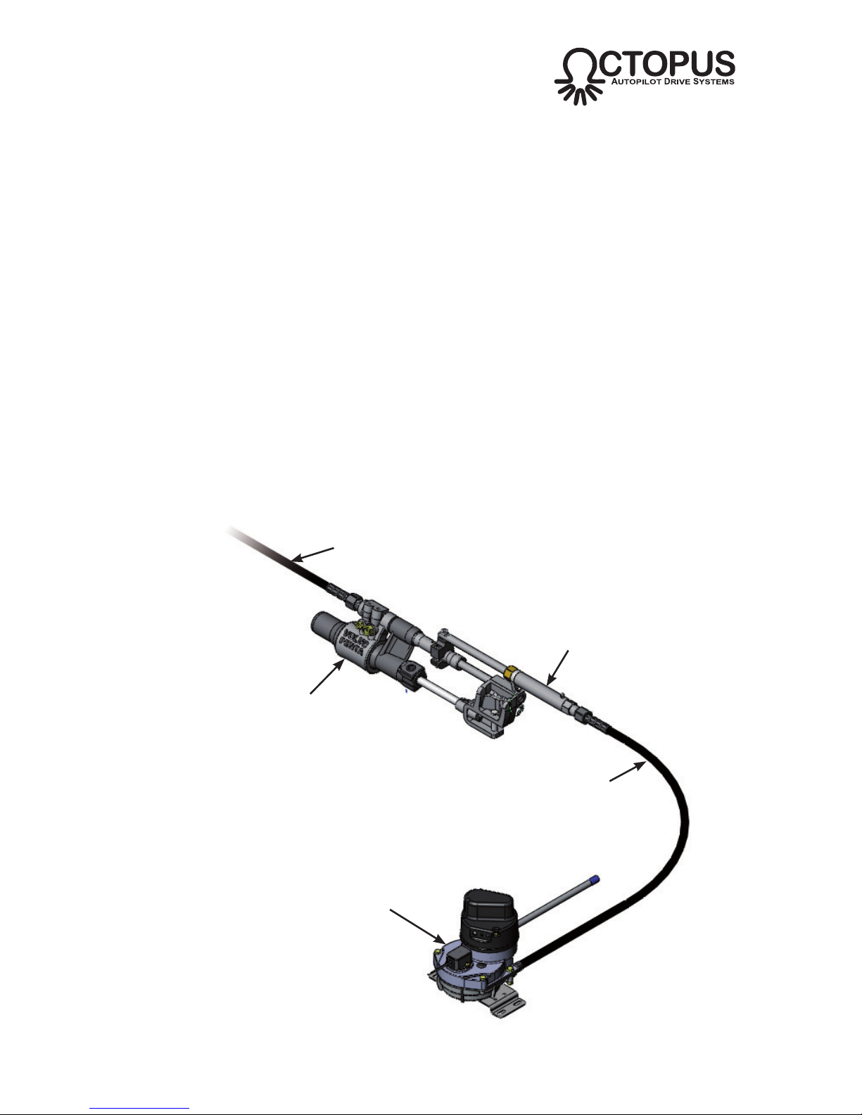
C ELECTRICAL INSTALLATION
C1 Connecting Drive to Autopilot
As the Type R Autopilot Drive is designed
to work with most autopilot manufacturers’
equipment, the wiring colors or connection
references will differ slightly in each case.
However, drive to autopilot connections
are fundamentally the same for all makes
of autopilot. The Type R drive has a simple
four wire connection - two wires are for
the drive motor power feed, the other two
are for the clutch (Fig C1). Refer to the
autopilot manufacturer’s instructions for
wiring information.
Note that the Type R drive requires a 12V
input for both the motor drive and the
clutch. Do not use with a 24V system.
C2 Rudder Feedback Unit
C2a Connection - non-Simrad Autopilots
i) Connect the RFB Module wires to
autopilot junction box - refer to Figs
C2 and C3 for the correct wiring
color connections for common
autopilot brands.
ii) Setup and calibrate the RFB as
described in section B10.
DRIVE CABLE
AUTOPILOT
RED MOTOR +12V
BLACK MOTOR -12V (0V)
GREEN CLUTCH +12V
WHITE CLUTCH -12V (0V)
Fig C1 - Motor and clutch cable connections
Fig C3 - Rudder Feedback connections by manufacturer
rfb raymarine navman tmq
course-
master
comnav garmin
si-teX
sP110 sP70/80
red red orange red orange power red +ve pin 3
black green black blue blue common black -ve pin 1
white blue blue green brown poSition Yellow wip pin 2
Shield Silver black black n/a n/a n/a n/a n/a
Fig C2 - RFB cable connections
39 of 44
Subject to change without notice OC15269 REV F
WWW.OCTOPUSDRIVES.COM
WWW.OCTOPUSEUROPE.COM
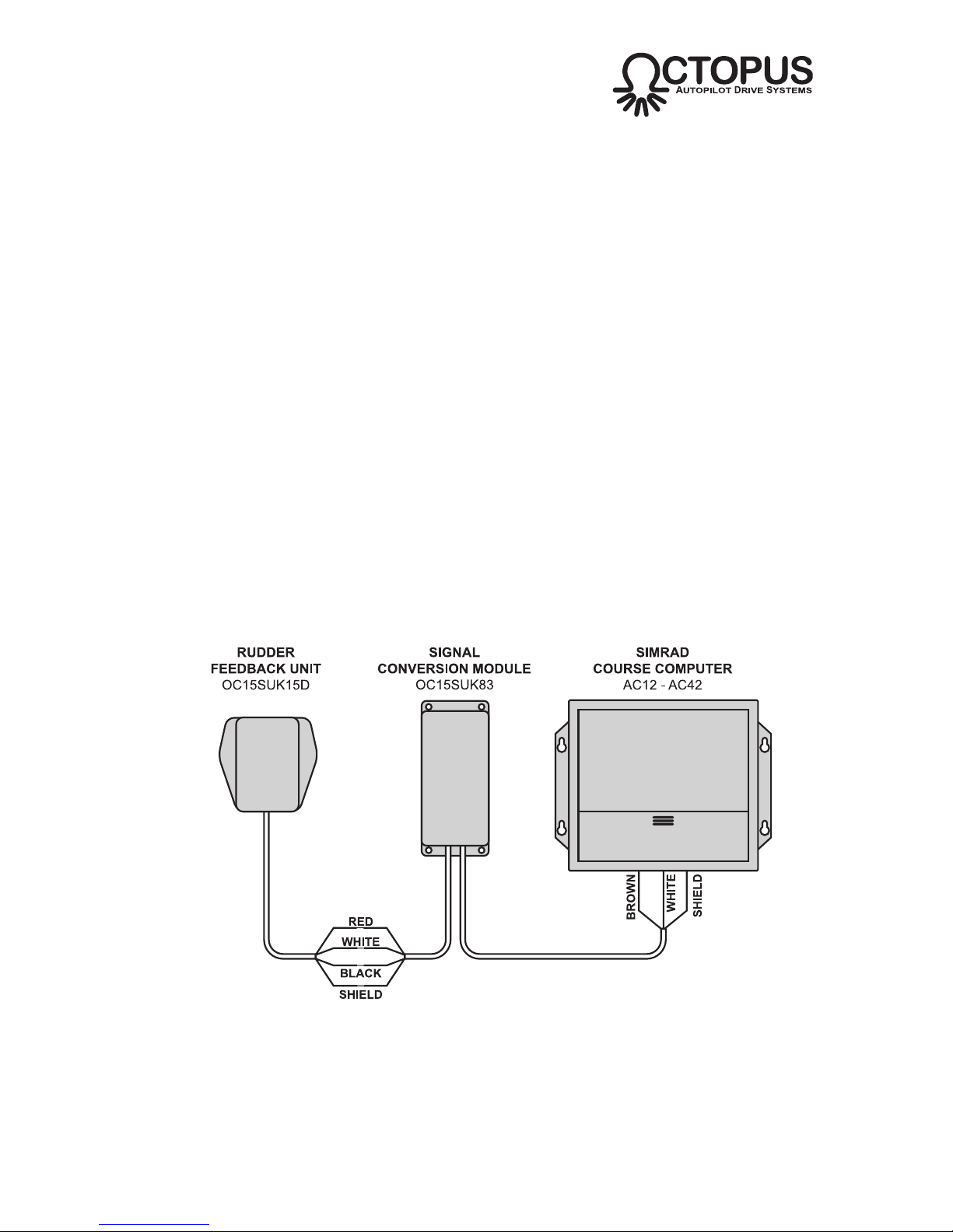
C2b Connection - Simrad Autopilots
The RFB Module OC15SUK27D MUST be used in conjunction with the Signal
Conversion Module OC15SUK83 when integrating with Simrad Autopilots.
i) IMPORTANT - all wiring connections must be made between the RFB
Module, the Signal Conversion Module and the Autopilot Course Computer
BEFORE powering up the Course Computer. Failing to follow this will result
in the RFB signal not being recognized by the Course Computer. If this
occurs perform the “Autopilot Reset” procedure (refer to Simrad autopilot
manual).
ii) Determine suitable site to mount the Signal Conversion Module. Shorten or
insert suitable extension cable as required to suit the installation.
iii) Connect the RFB Module, Signal Conversion Module and Autopilot Course
Computer together as shown in Fig C4. Use a marine grade electrical connection strip and ensure the wires are properly insulated and protected.
iv) Connect Octopus Signal Conversion Module output wires to Auto Pilot
Junction Box following Auto Pilot installation and wiring diagram.
v) Setup and calibrate the RFB as described in section B10.
Fig C4 - RFB connections - Simrad Autopilots

40 of 44
Subject to change without notice OC15269 REV F
WWW.OCTOPUSDRIVES.COM
WWW.OCTOPUSEUROPE.COM
D APPENDIX
D1 Accessories
OC15SUK12B
OC15SUK12C
OC15SUK15A
OC15SUK15B
OC15SUK19
OC15109-6
OC15109-9
OC15109-12
OC15SUK27
OC15SUK27A
OC15SUK27B
OC15SUK27D
OC15SUK27E
OC15SUK83
Type B - Multi I/O Connection Kit – To Fit to Sterndrive
Power Assist Steering Cylinders for Mercruiser engines (from
1994) and Volvo Gas engines & Volvo Diesel engines USA
(from 1997)
Type C - Multi I/O Connection Kit – To fit to Sterndrive Power
Assist Steering Cylinders for Mercruiser Saginaw (up to
1993) and Volvo Diesel drives Europe (from 1994)
Yamaha 115-220 O/B Installation Kit – for Second Steering
Cable Connection to Outboard
Mercury-Mariner-Suzuki O/B Installation Kit – for Second
Steering Cable Connection to Outboard
Universal Connection Kit – for Custom Steering Cable
Connection to Tiller or Quadrant
Standard Steering Cable x 6 foot long
Standard Steering Cable x 9 foot long
Standard Steering Cable x 12 foot long
Rudder Feed Back Module – Universal Kit for all versions
of Autopilots
Rudder Feed Back Module – For Comnav & Sitex
Rudder Feed Back Module – For Raymarine
Rudder Feed Back Module – For Simrad
Rudder Feed Back Module – For Coursemaster, Furuno,
Garmin & TMQ
Simrad Signal Conversion Module – Required for Simrad
Autopilots

D2 General Maintenance Guide
• Grease the installation kit by applying a grease gun to the grease nipple on the guide
tube after installation and at regular intervals thereafter.
• Check the complete steering system and all fixings for security and integrity after a
few hours of operation and at frequent intervals.
• Keep all moving parts free from build-up of salt and other foreign material - this will
adversely affect their operation and create steering problems. Pay particular attention
to the installation kit hardware.
• Inspect all parts periodically for corrosion. Any parts affected by corrosion must be
replaced.
• Periodically remove the cable, clean the connector tube and thoroughly lubricate with
a waterproof grease. Inspect the cable for cracks, splits or other damage. DO NOT
cover cracks in the cable outer sheath with tape or other sealant; this will only delay
a failure of the cable. Always replace the cable.
• When replacing fixings, self-locking nuts must always be used.
• The cable is a consumable item which should be replaced at regular intervals. It is
recommended that the cable is replaced after 150 -200 hours of use or every two
seasons. Note that incorrect installation, high torques or lack of maintenance will
reduce the life of the cable. For extensive cruising and long passage making; it is
recommended that a spare cable is kept onboard.
41 of 44
Subject to change without notice OC15269 REV F
WWW.OCTOPUSDRIVES.COM
WWW.OCTOPUSEUROPE.COM


OC15269 REV F
Octopus Products Inc.
Vancouver, Canada
Tel 604 940 2010
Fax 604 952 2650
www.octopusdrives.com
www.octopuseurope.com
 Loading...