


SmartModem
Reference
Guide
SmartModem
VoiceMaster
Socket Rocket
Revision C
January, 1996
YML212-3
NetComm Code Version V2.65

ISBN 0 947206 95 7
Copyright
This manual is copyright. Apart from any fair dealing for the
purposes of private study, research, criticism or review, as
permitted under the Copyright Act, no part may be reproduced,
stored in a retrieval system or transmitted in any form, by any
means, be it electronic, mechanical, recording or otherwise,
without the prior written permission of NetComm Limited.
Disclaimer
NetComm Limited accepst no liability or responsibility, for
consequences arising from the use of this product.
NetComm Limited reserves the right to change the specifications and
operating details of this product without notice.
Trademarks
NetComm, ProRack, Faxnet, CellModem and Cooee are
registered trademarks of NetComm Limited
SmartModem, AutoModem, PocketModem, Smart/Rack, PC Fax Card,
FastFix, TNP, and AutoSoft are trademarks of NetComm Limited
MNP is a registered trademark of Microcom Inc
Microcom Networking Protocol is a trademark of Microcom Inc
Hayes is a registered trademark of Hayes Microcomputer
Products Inc
IBM is a registered trademark of International Business
Machines Corporation
MS-DOS is a registered trademark of Microsoft Inc
WordStar is a registered trademark of Micropro International
Corporation
WordPerfect is a registered trademark of WordPerfect
Corporation
©1995 NetComm Limited ACN:002490486
PO Box 379 North Ryde NSW 2113 Australia
Incorporated in New South Wales Australia
SmartModem Reference Guide
i

NetComm Limited
SOFTWARE PROGRAM LICENSE
1. NetComm grants its Customers a non-exclusive license (the “License”) to use any
software programs (the “Programs”) used in connection with the Products and supplied
by NetComm.
2. The Customer assumes responsibility for the selection of the Programs to achieve its
intended results and for the installation, use and results obtained from the Programs.
3. The Customer may:
(a) use the Programs on a single machine;
(b) copy the Programs into any machine readable or printed form for backup
purposes in support of use of the Programs on a single machine (certain
Programs may, however, include mechanisms to limit or inhibit copying); and
(c) transfer the License to a purchaser of the relevant Products and the Customer
shall at the same time either deliver all copies of the Programs, whether in
printed or machine-readable form, to the purchaser or destroy any copies not
so delivered.
4. The Customer shall bring to the attention of any transferee of the License these terms
upon which the License is granted.
5. If for any reason the License is terminated, the Customer shall procure the destruction
of all Programs (including all copies of them).
6. NetComm warrants that the Programs will carry out the functions described in the
Product Manual but does not warrant that the Programs or any particular copies of
them will be free from particular defects. If the Programs are found to be defective,
NetComm will replace the Programs provided the medium on which the Programs
reside is returned (shipping prepaid and properly packed) to NetComm. Proof of
the Customer’s license to the satisfaction of NetComm must accompany any request
for warranty.
7. Improved or modified versions of the Programs may be made available under license
to the Customer, at NetComm’s absolute discretion and upon payment of its then
current Charges. NetComm may require the return or destruction of previous versions
of the Programs and evidence of the License to use those Programs. New versions
shall be licensed to the Customer upon the same terms and conditions as are contained
in this Clause 7 and the License to use prior versions of the Program shall terminate
upon delivery to it of the new versions of them.
ii
SmartModem Reference Guide

HARDWARE WARRANTY
1. NetComm grants a warranty in relation to the Products for the period set
out in the relevant Product Manual, from the original date of purchase, on
the following conditions:
(a) this warranty covers component failure, defective materials and
production defects only;
(b) warranty if it complies with all of the terms of the Agreement and any
other reasonable requirements of NetComm including producing such
evidence of purchase as NetComm may require;
(c) the Customer may not rely on this warranty if any cost, loss or damage
to the Products or otherwise arises as a result of or in connection with
the negligence or default (including but not limited to any failure to
comply with the Product Manual or NetComm’s training) of the
Customer;
(d) the Customer shall be solely responsible for delivery of the Products to
and from NetComm’s nominated premises; and
(e) this warranty shall not apply to the Programs.
2. No Products shall be returned to NetComm for repair or replacement under
any warranty provided under the Agreement without NetComm’s prior
written consent.
LIMITATION OF LIABILITY
NetComm will have no liability to its Customers under the above warranties
beyond what is set out in them. NetComm liability under implied warranties
and conditions is limited to that set out in its standard terms and conditions.
SmartModem Reference Guide
iii

Contents
CONTENTS
Introduction............................................................ 1
How to Use This Guide .......................................... 1
Conventions ............................................................ 3
Getting Started........................................................ 5
The AT Commands ................................................ 5
The Attention Code .......................................... 5
Multiple Commands ......................................... 5
The Escape Sequence ........................................ 6
The Repeat Command ......................................7
The Help Command ......................................... 7
Response Codes ................................................ 7
Dialling .................................................................. 8
Dial Modifiers .................................................. 9
Hanging Up ...................................................11
Stored Number Dialling .................................12
Answering Calls.................................................... 13
Selecting Speeds.................................................... 15
Terminal Speeds ............................................. 15
Setting Terminal Speeds ................................. 16
Line Speeds ..................................................... 17
V.34 Modem Typical Settings ........................ 18
V.32bis Modem Typical Settings .................... 19
Flow Control......................................................... 21
RTS/CTS Flow Control ................................... 21
XON/XOFF Flow Control.............................. 21
Transparent XON/XOFF Flow Control .......... 22
Failsafe Flow Control ......................................22
The Inactivity Timer ............................................ 23
The Command Timer ........................................... 23
Configuring the Modem ....................................... 23
Viewing the Current Configuration ................ 24
Testing ................................................................ 25
The Test Timer..................................................... 25
Terminating a Test - &T0..................................... 25
iv
SmartModem Reference Guide

Local Analog Loopback Test - &T1 .......................25
Local Digital Loopback Test - &T3 .......................27
Grant RDL from Remote Modem - &T4............... 28
Deny RDL from Remote Modem - &T5................ 28
Remote Digital Loopback Test - &T6 ...................28
Remote Digital Loopback with Self Test - &T7 .... 30
Local Analog Loopback & Self Test - &T8 .............32
Error Correction ................................................... 33
Error Correction Protocols .................................... 33
Data Compression .................................................34
Reliable Mode....................................................... 35
Auto-Reliable Mode ............................................. 35
Improving Performance with MNP 10.................. 37
Speed Changes ................................................ 38
Cellular Modem Users .................................... 39
Which Error Correction Do I Use?........................ 39
Increasing Data Throughput with
Error Correction & Data Compression ............. 40
Contents
Digital Simultaneous Voice & Data (Digital SVD) ..... 41
Setting up for Digital SVD ................................... 41
Using the Telephone to make Normal
Voice Connections .......................................... 41
Starting a Digital SVD Connection after you have
Established a Normal Voice Connection ..... 42
Starting a Digital SVD Connection after you have
Established a Normal Voice Connection ..... 43
Security & Encryption .......................................... 44
The Security Menu................................................ 45
Entering Security Password ............................ 45
Adding and Changing Users ...........................46
Removing Users ............................................. 47
Listing Existing Users .................................... 47
The Access Record .......................................... 47
Enabling Modem Security .............................. 48
SmartModem Reference Guide v

Contents
Quitting the Menu ......................................... 49
Callback Security .................................................. 49
Downloading the Security File........................ 51
Uploading the Security File ............................ 51
Encryption............................................................ 52
SuperSecure Advanced Security Mode ................... 54
Entering Key forEach User ............................. 54
Accessing Using SuperSecure .......................... 55
Connection ..................................................... 56
Disconnection ................................................. 56
Enabling Rotating Secondary Keys ....................... 57
Symmetrical Operation .........................................58
Automatic Synchronisation ...................................58
Password Expiry Option ....................................... 58
Entering in Remote ........................................59
Entering in Local ............................................59
Minimum Length ........................................... 59
Additional User Options....................................... 60
Up & Downloading the SuperSecure Database ...... 60
Security Database Lock Option ............................. 61
Outdial Disable Option ........................................ 61
Dial Stored Phone Numbers Only Option............. 62
General Notes on Data Security ............................ 62
Synchronous Modes .............................................. 63
Synchronous Operation .........................................63
Terminal Speeds ............................................. 63
Line Speeds ..................................................... 64
Synchronous Mode 1 ....................................... 65
Selecting..................................................... 66
Dialling...................................................... 66
Hanging Up ............................................... 67
Answering Calls ......................................... 67
Synchronous Mode 2 ....................................... 68
Selecting..................................................... 69
Dialling...................................................... 69
vi
SmartModem Reference Guide

Hanging Up ............................................... 69
Answering Calls ......................................... 69
Leased Line Operations ......................................... 70
Smart Leased Line Mode ................................. 71
Calling & Answering Using &L1 ................71
Auto Leased Line Operation (&L2 or &L3) ..72
Hanging Up ............................................... 72
Improving the Reliability of
Leased-Line Connections............................. 73
Dumb Mode Operation ........................................ 74
Selecting Dumb Mode .......................................... 74
on Desktop Modems ....................................... 74
on ProRack Modems....................................... 75
Setting up your Modem ........................................ 75
Selecting Communications Speeds
on Desktop Modems ...................................... 76
on ProRack Modems....................................... 77
Hints for Unix Computers & Multiplexers ............ 78
Dialling in Dumb Mode ....................................... 78
Dialling with telephone handset ..................... 79
Using Talk/Data Button to dial ......................80
Using DTR to Dial......................................... 81
Answering Calls in Dumb Mode ........................... 83
Automatic Answering..................................... 83
Manual Answering ......................................... 84
The Option Switches ............................................ 86
Modems with Rear Panel Option Switches ..... 86
Modems without Rear Panel Option Switches 87
ProRack Modems ........................................... 88
Contents
CCITT V.25bis Operations .................................. 89
Selecting V.25bis Operation ................................. 89
Overridden Settings........................................ 90
V.25bis Commands .............................................. 91
Data Formats ........................................................ 91
V.25bis Indications............................................... 91
Dialling ................................................................ 92
SmartModem Reference Guide vii

Contents
Dial Modifiers ................................................ 93
Hanging Up ...................................................95
Stored Number Dialling .................................95
Direct Dialling ...............................................95
Answering Calls.................................................... 96
Selecting Speeds.................................................... 97
Terminal Speeds ............................................. 98
Line Speeds ..................................................... 98
Modem Cable ....................................................... 99
Synchronous Character Encoding .......................... 99
Asynchronous Notes ........................................... 100
BSC Notes .......................................................... 100
HDLC Notes ...................................................... 100
Command Descriptions...................................... 101
Alphabetical Command listing ........................... 101
Full Command Descriptions ............................... 104
V.25bis Commands ...................................... 105
S Registers .......................................................... 228
Introduction ....................................................... 228
Reading and Changing S Registers ..................... 228
S Register Settings and Modem Memory............. 229
Full S Register details .........................................231
viii
Troubleshooting ................................................. 271
Introduction ....................................................... 271
Some Problems and Solutions ............................. 271
Troubleshooting Flow Chart ............................... 275
Testing Your Modem.......................................... 277
Sample Setups ..................................................... 278
Asynchronous Mode............................................ 278
Calling a BBS or EMail System ..................... 278
Using as an Auto-Answer Modem ................ 279
Using Connected to UNIX Computer .......... 281
Using in Leased Line Mode ...........................282
Synchronous Mode .............................................. 283
SmartModem Reference Guide

Appendices ......................................................... 284
Appendix A ........................................................ 284
Modem Response Codes ...................................... 284
V.25bis Indications ...................................... 285
Appendix B ........................................................ 286
ASCII Table........................................................ 286
Appendix C ........................................................ 287
RS-232 Signals ................................................... 287
Glossary ............................................................... 290
Index ................................................................... 315
Contents
SmartModem Reference Guide ix

Introduction
INTRODUCTION
Welcome to the SmartModem Reference Guide, a comprehensive
guide to the efficient use of your modem.
Together with the Installation Guide & Command Card supplied with
your modem, this reference manual provides all the information needed
to make maximum use of your equipment and software.
The SmartModem Family contains a range of different models.
Model Type DSVD SS Rack Voice Series
M7F V.32bis X 5
V8 V.32bis X 5
M11F V.FC X 5
M34F V.34 X 5
288 V.34 X X 6
288D V.34 X X 6
☞ SS = SuperSecure
Rack = Rack version available with SNMP
X.32 is available as an option on some models
Introduction
How to Use This Guide
The SmartModem Reference Guide is divided into the following
sections:
Introduction
❏ Provides you with an easy-to-understand guide to what’s in this
manual and how you can make the most of the information.
Getting Started
❏ A complete description about how to get started using your
equipment, including basic details and more advanced topics.
Testing
❏ Details each of the many tests you can carry out to determine the
working condition of your modem, the telephone line, or the
remote modem.
SmartModem Reference Guide
1

Introduction
Error Correction
❏ Examines and explains the error correction features,
Introduction
Digital SVD
❏ Explains how to use Digital Simultaneous Voice and Data
Security
❏ Examines and explains the data security and encryption
Synchronous & Dumb Modes
❏ Full details on how to use your modem for synchronous operations.
Dumb Mode
❏ Provides product specified information on Dumb Mode operation.
V.25bis Operations
❏ Describes how your modem implements V.25bis and how it
AT Commands
❏ Provides a complete description of all commands available in
S Registers
❏ Introduces you to S Registers and how to use them.
❏ Contains a description of the available S Registers.
Troubleshooting
❏ Provides basic guidelines for solving problems.
Sample Setups
❏ Provides sample setups showing how commands can be combined.
Appendices
❏ The appendices contain useful lists, as well as an ASCII table.
Glossary of Communications Terms
❏ Provides descriptions of modem, facsimile and other
includingV.42bis data compression, of your equipment.
facility.
features of your equipment.
interacts with AT commands.
your modem.
communications terms.
2
SmartModem Reference Guide

Conventions
Throughout this guide, we use certain symbols, typestyles and
conventions to help you. For example, you might find a line that
looks like this:
• Type:
(that is ‘ATI9’ not ‘AT19’)
What you actually type appears in a special typeface:
ATI9
Whatever appears on your screen will also be displayed in this
manual in this special typeface — for example: messages:
CONNECT
When we want you to press the ENTER key, we use a symbol:
ATI9 <E>
<E> (which means ‘and press
ENTER’)
Introduction
Introduction
On some keyboards the
RETURN or ENTER, as appropriate for your keyboard. The same is
true for keyboards showing a symbol, rather than
ENTER.
RETURN = ENTER =
In some cases where the <E> symbol might be confusing, we will tell
you to ‘Press the
When you see the bullet (•), it usually starts an action statement.
We want you to take some specific action, such as:
• Switch your computer on
• Type:
Note that we do not use a (.) full stop after an action statement.
We do that to avoid confusion when you are asked to type
commands and other information.
When we list general information, we use a box (❏), like this:
SmartModem Reference Guide
ENTER key is labelled RETURN. You press
RETURN or
ENTER key’.
ATI9 <E>
3

Introduction
❏ How to begin dialling
❏ Using MNP for error-free communication
Introduction
When we have special information we want you to take NOTE
of, we use a pointing finger (
☞Before proceeding, complete both copies of the Warranty
Information we want you to pay special attention to is placed in
a WARNING box, like this:
DEFAULTS are settings which are preset in the factory. Default
settings are indicated in this guide by the symbol: ■
For example, if the default was AT&G0 in this list:
■ AT&G0 Do not generate guard tones
☞), like this:
form.
WARNING
Regulations require that the modem,
when operating in originate mode, waits no
longer than 30 seconds for a carrier to be
detected from a remote modem.
AT&G1 Generate Guard tones of 550Hz
AT&G2 Generate Guard tones of 1800Hz
There is a Glossary at the back of this Reference Guide to assist
you with unfamiliar words.
4
SmartModem Reference Guide

Getting Started
GETTING STARTED
The AT Commands
The AT commands are a group of special commands recognised
by your modem. These commands derive their name from the
letters AT, which are used to prefix commands. Before continuing:
• Run your communications software and enter local mode (or
terminal mode) at 2400 bps Refer to your communication
software manual for details.
The Attention Code
An AT (sometimes known as the ATtention code) usually
precedes all commands being sent to the modem. It is used to
gain the modem’s attention, informing it that you are about to
send a command. For example:
• Type the command: ATI9 <E>
Your modem’s firmware identity message will appear on your
computer screen. If you type I9 only, your modem will not
respond. If you type AT19, your modem will report an
ERROR.
Getting Started
You may enter the attention code in all upper case, or all lower
case letters, such as:
Multiple Commands
You may place multiple modem commands after an AT provided
the total number of characters does not exceed 80. For example,
a valid command to display the modem’s firmware identity twice
is:
• Type in the command: ATI9I9 <E>
An AT is not required in front of the second I9 command.
You only need one attention code for each
command line. To make this command more readable,
you can add spaces between the two commands:
• Type in the command: AT I9 I9 <E>
The modem will execute the command as if the spaces are not
there.
SmartModem Reference Guide
AT or at
5

Getting Started
The Escape Sequence
When you issue commands to the modem all dialogue is occurring
between your computer and the modem. This situation is
known as local command state.
When you connect to a remote system, dialogue will be occurring
between your computer and the remote system. This is known
as on-line state. Because the modem assumes, after it enters online state, all the data you send it is to be sent on to the remote
Getting Started
modem, it ignores any AT commands you give it while in online state.
To force the modem to return to local command state, enter an
escape sequence. An escape sequence consists of a one second
delay, three + characters typed rapidly and another one second
delay. For example:
• Type: AT&T1 <E>
The modem will enter on-line state (this command actually
causes the modem to enter test mode, but is equivalent to
entering on-line state).
Now try to view the modem’s firmware identity code:
• Type: ATI9 <E>
Your command will be ignored. This is because the modem
assumes you aretyping characters to be sent to a remote
system.
Now enter an escape sequence. Do not type any characters for
one second, type +++ rapidly and wait another full second. The
modem will respond with an OK message to indicate it has
returned to local command state. You will be able to view the
modem’s firmware identity.
Before continuing:
• Type: AT&T0 <E>
This command is used to halt the test.
6
SmartModem Reference Guide

The Repeat Command
The repeat command is used to re-execute the last command
issued to the modem. Issue the ATI9 command and the
modem’s firmware identity code will be displayed on the screen.
• Type: A/
The identity code will appear again.
You don’t have to enter AT before the repeat command. You also
do not have to press the
ENTER key. This is the only modem
command which does not require you to enter AT before it, and
one of the few commands which does not require you to press the
ENTER key. The A/ command is intended primarily for re-
dialling a telephone number that was previously engaged.
The Help Command
Your modem will display information about the AT commands
it supports if you type a question mark (?) in your AT command.
For example:
• Type: AT? <E>
Your modem will display a list of all the commands it
supports.
• Type: AT?DTR <E>
Your modem will display a summary of commands involving
DTR.
• Type: AT?\N3%C2&D2 <E>
Your modem will display summaries of the \N, %C and &D
commands.
Getting Started
Getting Started
Response Codes
Your modem is capable of telling you, with on screen messages,
what it is doing. These messages are known response codes or
result codes, and you will see them from time to time.
For example:
After a command is successfully executed, the response is:
OK
After a connection is established, the response is: CONNECT
A complete list of Response Codes can be found in Appendix A.
SmartModem Reference Guide
7
Getting Started
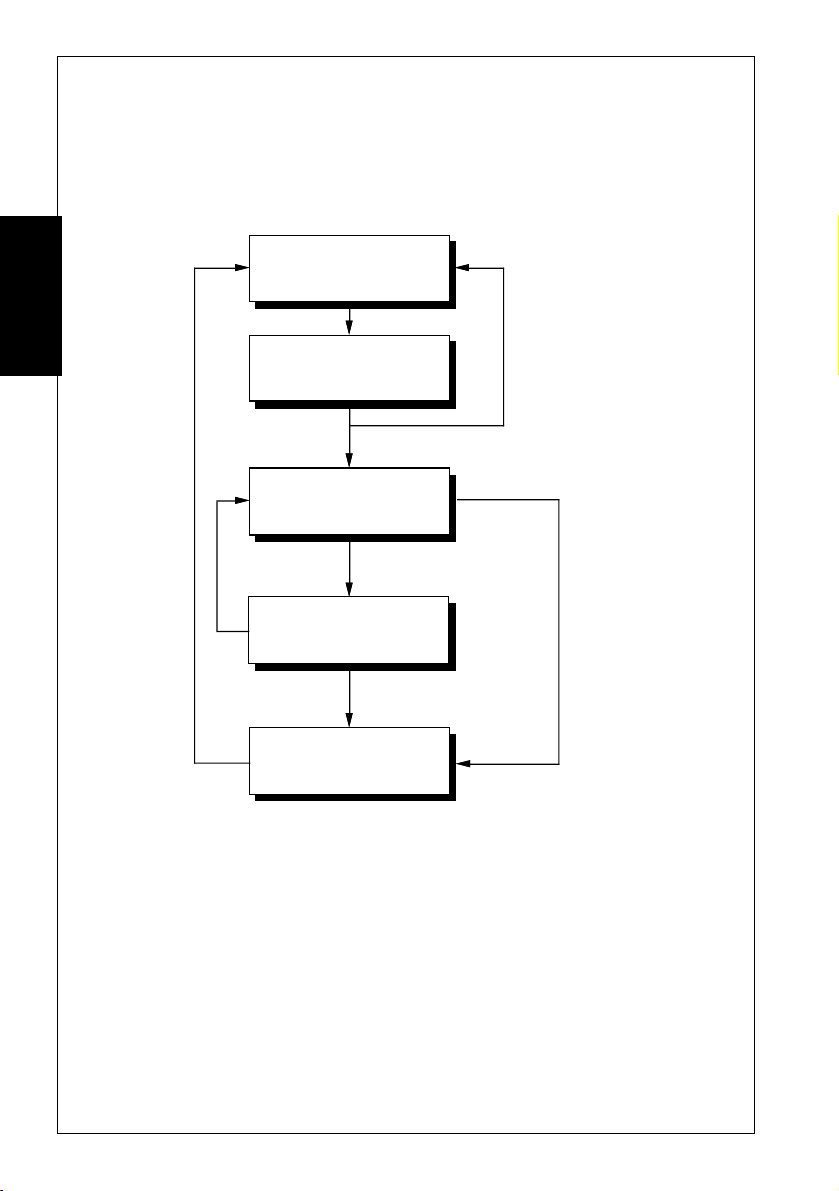
Dialling
The AT commands may be used to initiate dialling with the
modem. Your modem does not require a telephone handset to
be connected to it in order to dial.
Asynchronous
Local Command State
Getting Started
The D (Dial) command is used to initiate a telephone call. The
most basic form of the D command is:
ATD number
where the number is the telephone number you are dialling.
Having set your communications software for 2400 bps operation:
• Type: ATD01234 <E>
Your modem will begin to dial.
ATD issued
Phone # busy or
connection failed
Connection established
ATO
Asynchronous
On-line State
Escape sequence
entered (+++)
Local Command State
ATH issued
Hang Up
Asynchronous Originate Mode
Carrier lost or
DTR lowered (&D2)
8
SmartModem Reference Guide

Getting Started
☞ If your modem receives a character from your computer while
dialling is being performed, it will immediately hang up,
send a NO CARRIER response message to the computer and
return to local command state.
After a few seconds the message CONNECT will appear on the
screen.
If a NO CARRIER message appears, then your modem has not
been able to make a connection. Check your communications
software is set for 2400 bps operation and your modem is
correctly connected to your computer and the telephone line.
You may use the A/ command to redial.
To hang up the modem, enter an escape sequence (+++). The
modem will respond with an OK message.
• Type: ATH <E>
The modem will hang up.
☞ Your computer must assert the DTR signal before dialling
can start. Usually, this is done by your communications
software. If the DTR signal is lowered at any stage of
communications, after the &D2 command has been issued,
the modem will hang up and return to local command state.
Interpretation of the DTR signal may be changed with the
&D command.
Getting Started
Dial Modifiers
Dial modifiers are characters than can be included in a phone
number to make the modem perform special tasks while dialling.
For example, not all modem users will be using a dedicated
telephone line. Some users will have their modems connected to
PABXs. To allow users of PABXs to operate their modems
successfully, dial modifiers are supported on the modem.
Most PABXs require you to dial 0 or 9 (in order to obtain an
outside line) and wait for a dial tone before dialling the actual
phone number.
SmartModem Reference Guide
9

Getting Started
Using dial modifiers, you can successfully dial the phone number
12345 through a PABX using the command:
ATD0,12345
The , (comma) dial modifier causes the modem to pause for
a short time after dialling 0. This allows most PABXs
sufficient time to obtain a line before dialling.
The factory default delay for the , modifier is two seconds. You
may change the length of this delay if necessary. Its length is
determined by the value in S Register 8.
Getting Started
Another method of making the modem wait for a dial tone is to
include the W dial modifier. The W modifier causes the modem
to examine the phone line to ensure a dial tone has been applied
before dialling starts:
ATD0W12345
If the modem cannot detect a dial tone within the time
specified by S Register 7, the modem will return to local
command state and send a NO DIALTONE message to the
computer (if either the X2, X4, or X5 commands have been
issued).
10
Due to differences with some older telephone exchanges, dial
tone detection may not be possible with your modem. Your
modem will only recognise dial tones between 200 Hz and 600
Hz.
If your telephone line supports tone dialling then a useful dial
modifier is the T modifier. Inserting a T modifier before the
number you are dialling causes the modem to tone dial that
number. For example:
ATDT12345
This will cause the modem to dial the phone number 12345.
The modem also supports a P dial modifier which allows it to
pulse dial. These modifiers may be placed at any point in the
number you are dialling and they may be intermingled in the
same number.
SmartModem Reference Guide

Getting Started
For example, your telephone line may be connected to a PABX
that supports tone dialling internally, but only pulse dialling
externally. You could overcome this problem by using the T
and P dial modifiers in the following way:
ATDT0,P12345
The modem tone dials 0 to request an external line, waits for the
PABX to obtain the line and then pulse dials 12345.
Although most telephone exchanges support tone dialling,
there are still a few pulse only exchanges. If you can hear a
continuous dial tone when you lift the handset, you will probably
be able to tone dial. If you are in any doubt, use pulse dialling.
The modem will automatically pulse dial if you have not
previously included either the T or P modifiers in your phone
numbers. Exchanges that support tone dialling generally support
pulse dialling as well.
More information about dial modifiers can be found in the
Command Descriptions chapter of this guide.
Getting Started
☞ Pulse dialling may not be supported in New Zealand. Refer
to your Installation Guide for details.
Hanging Up
The H command is used to hang up the modem. After you have
finished communicating with another computer you must hang
up your modem. Similarly, you must hang up the phone after
calling another person. If you don’t, no one will be able to call
you and you may even be charged for the length of time the
phone was off the hook.
To hang up your modem:
• Type: ATH <E>
The modem will return an OK response message.
SmartModem Reference Guide
11

Getting Started
Stored Number Dialling
Your modem has the ability to store phone numbers which may
be dialled at a later time. This is similar to ‘abbreviated
dialling’, which may be supported by your telephone.
To store a phone number use the &Z command. For example:
• Type: AT&Z1=012345 <E>
The phone number 012345 will be stored as phone
number one.
Getting Started
The S dial modifier is used to dial a phone number that has been
stored in your modem:
• Type: ATDS=1 <E>
The modem will dial stored phone number one.
☞ Do not include an AT, D command, or S dial modifier in the
stored phone number. If synchronous mode 2 is being used,
the ; (semi-colon) dial modifier should not be included.
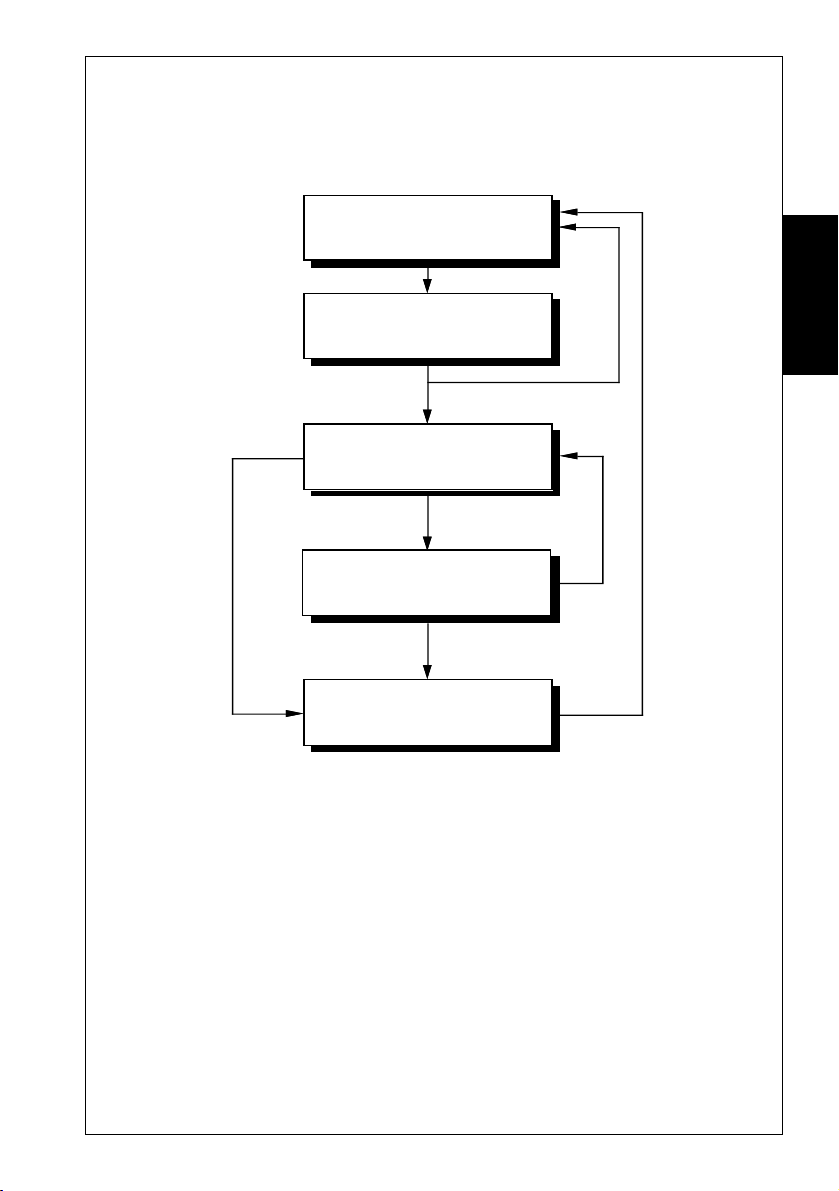
Answering Calls
As well as dialling other modems, your modem can answer calls
made to it by other modems.
Your modem is pre-configured to automatically answer any
incoming call, provided it is switched on, is in local command
state, DTR is high and is not performing a test. If you receive
a call on the phone line the modem is connected to, it will answer
the call and attempt to connect to the calling modem.
S Register 0 contains the number of rings the modem will wait
before answering a call. If a value of 4 is placed in S Register 0,
the modem will answer an incoming call immediately after the
fourth ring. If a 0 value is placed in S Register 0, the modem will
not answer an incoming call.
12
SmartModem Reference Guide
Getting Started
The communications standard used by the modem in its attempt
to connect with a calling modem is determined by the B
command.
Carrier
lost or
DTR
lowered
(&D2)
Asynchronous
Local Command State
ATA or
Incoming call
Connection
failed
Connection established
Asynchronous
On-line State
Escape sequence
entered (+++)
Local Command State
ATH issued
Hang Up
Asynchronous Answer Mode
Getting Started
ATO
SmartModem Reference Guide
13

Getting Started
If the phone does ring, and verbal response codes are selected
(ATV1), the modem will issue
of rings stored in S Register 0 is reached. The modem will then
go on line, transmit an answer tone, and attempt to connect to
the calling modem using the communications standard selected
by the B command.
By default the modem is set to B0. B0 is the auto range setting.
Getting Started
This should connect to virtually all communications standards
and normally you do not have to alter this.
As soon as a connection is established, the modem will send a
CONNECT message to your computer and enter on-line state in
answer mode.
RING messages until the number
14
SmartModem Reference Guide
Selecting Speeds
R
•
•
The following section describes how to select line and terminal
speeds for your modem.
Your Computer
Terminal
speed
Modem
Modem
Line
speed
Telephone
Exchange
emote
Computer
Getting Started
Getting Started
Line
speed
Terminal
speed
Terminal Speeds
Your modem has the ability to communicate with your computer
at various speeds. (Refer to your Command Card for details on
which speeds are available in your modem.) The modem offers
two speed modes: variable speed mode and constant speed mode.
Constant speed mode forces your modem to maintain the terminal
speed that was selected when you dialled another modem, even
if the connection speed made with the other modem does not
match the terminal speed of your modem and computer.
For example, if your modem connected to another modem at
2400 bps and its terminal speed is 9600 bps, the modem will
maintain its terminal speed at 9600 bps. Because of this, you
must select flow control between the modem and your computer.
To select constant speed mode:
• Type:
For more details on constant speed mode and flow controls, see
the Command Descriptions chapter for a discussion of the \N, B
and &K commands.
AT\N0 <E>
15SmartModem Reference Guide

Getting Started
☞ Some computers cannot cope with receiving data at speeds
Variable speed mode allows your modem to automatically
adjust its terminal speed to match the line speed. For example,
Getting Started
if your modem connects to another modem at 4800 bps and its
terminal speed is 9600 bps, the modem will automatically
change its terminal speed to 4800 bps (and, thus, you or your
software would have to change the speed of your computer to
4800 bps).
If you have variable speed mode and B0, B1, B2 or B9 selected,
the modem will attempt to connect at a speed to match the
terminal speed.
At 300 bps, select B0 or B2 for V.21, or B1 for Bell 103. At
1200 bps, select B0 for V.23, B1 for Bell 212A, or B2 for V.22.
above 19,200 bps. If you wish to run at high speeds, you
should install a COM port that has a 16550 chip in place of
your regular COM port. The 16550 chip allows your
computer to accept data at very high speeds when used with
suitable drivers and software.
Variable speed mode may be selected by:
• Type: AT\N1 <E>
For more details about the variable speed mode, see the \N and
B commands in the Command Descriptions chapter of this
guide.
Setting Terminal Speeds
Your modem can sense the terminal speed of the computer and
automatically change its terminal speed to match. This is
known as ‘auto bauding’, and is done each time an AT command
is issued to the modem.
Your modem can auto baud at 300 bps through 9600 bps,
14,400 bps, 19,200 bps, 28800 bps,38,400 bps, 57,600 bps
and 115,200 bps.
16
SmartModem Reference Guide

Getting Started
The R command may also be used to disable autobauding and
lock the terminal speed. Refer to the R command for available
speeds.
Line Speeds
The B command determines the speed at which your modem
connects to another modem. Some or all of the following B
commands are provided by your modem (refer to your modem’s
Installation Guide for details on which communications standards
are supported):
SettingSelection
Command Speed Command Speed
B0 n Auto-Connect B16 V.34 at 14,400bps
B1 Auto-Connect B17 V.34 at 16,800 bps
B2 Auto-Connect B18 V.34 at 19,200 bps
B3 V.21 at 300 bps B19 V.34 at 21,600 bps
B4 Bell 103 at 300 bps B20 V.34 at 24,000 bps
B5 V.23 at 1200/75 bps B21 V.34 at 26,400 bps
B6 V.22 at 1200 bps B22 V.34 at 28,800 bps
B7 Bell 212A at 1200 bps B23 (Reserved for V34bis)
B8 V.22bis at 2400 bps B24 (Reserved for V34bis)
B9 Auto-Connect B25 (Reserved)
B10 V.32 at 4800 bps B26 (Reserved)
B11 V.32bis at 7200 bps B27 V.34 at 2400 bps
B12 V.32 (Non-TCM) at 9600 bps B28 V.34 at 4800 bps
B13 V.32 at 9600 bps B29 V.34 at 7200 bps
B14 V.32bis at 12,000 bps B30 V.34 at 9600 bps
B15 V.32bis at 14,400 bps B31 V.34 at 12,000 bps
Getting Started
In most cases you should select B0, as this setting attempts to
connect at any speed supported by the modem.
17SmartModem Reference Guide

Getting Started
V.34 Modem Typical Settings
Here are some example settings that may be relevant to the way
in which you wish to operate your V.34 modem.
Example 1 - Dialling other modems at the highest possible
speed and/or answering incoming calls.
Getting Started
B Command Setting: B0
Terminal Speed: 115,200 bps
Flow Control: On (&K9 for either RTS/CTS or XON/
Use this arrangement when dialling online information services
or bulletin boards. With these settings, you modem will
attempt to connect at any speed from 28,800 bps to 1200 bps.
These are the default settings of your modem.
If you wish your modem to answer incoming calls, use these
settings. This will allow your modem to connect at any speed
between 28,800 bps and 300 bps. If you are using a software
program that controls the answering of your modem (as some
bulletin board systems do) you may need to issue an ATS0=0
command to disable auto-answering, otherwise issue ATS0=2
to make the modem answer calls after two rings (the default
setting).
Example 2 - Dialling other modems at 19,200 bps (V.34 or
V.FC)
XOFF flow control)
18
B Command Setting: B18
Terminal Speed: 57,600 bps
Flow Control: On (&K9 for either RTS/CTS or XON/
XOFF flow control)
You may use this arrangement when dialling online information
services or bulletin boards. With these settings, you modem
will attempt to connect at 19,200 bps, but may change the line
SmartModem Reference Guide

Getting Started
speed if the quality of the telephone line does not support this
speed.
Example 3 - Dialling information services at 1200 bps (or V.22)
B Command Setting: B6
Terminal Speed: 38400 bps
Flow Control: On (&K9 for either RTS/CTS or XON/
XOFF flow control)
Some information services do not provide connections higher
than 1200 bps; these settings allow you to connect to such
services. Problems may also occur if error correction is switched
on; if the information service does not support V.42 or MNP,
issue the \N0 command before dialling.
V.32bis Modem Typical Settings
Here are some example settings that may be relevant to the way
in which you wish to operate your V.32bis modem.
Example 1 - Dialling other modems at the highest possible
speed
B Command Setting: B0
Terminal Speed: 38,400 bps
Flow Control: On (&K9 for either RTS/CTS or XON/
XOFF flow control)
Getting Started
Use this arrangement when dialling online information services
or bulletin boards. With these settings, your modem will
attempt to connect at any speed from 14,400 bps to 1200 bps.
These are the default settings of your modem.
19SmartModem Reference Guide

Getting Started
Example 2 - Dialling other modems at 14,400 bps (or V.32bis)
B Command Setting: B15
Terminal Speed: 38,400 bps
Flow Control: On (&K9 for either RTS/CTS or XON/
XOFF flow control)
Getting Started
You may use this arrangement when dialling online information
services or bulletin boards. With these settings, your modem
will attempt to connect at any speed from 14,400 bps to 1200
bps. Because V.32bis operation is not suitable on poor-quality
telephone lines, we recommend you use these settings with
caution; if you have trouble connecting to another modem using
V.32bis, revert to the settings shown in Example 1.
Example 3 - Answering incoming calls
B Command Setting: B9
Terminal Speed: 38,400 bps
Flow Control: On (&K9 for either RTS/CTS or XON/
If you wish your modem to answer incoming calls, use these
settings. This will allow your modem to connect at any speed
between 14,400 bps and 300 bps. If you are using a software
program that controls the answering of your modem (as some
bulletin board systems do) you may need to issue an ATS0=0
command to disable auto-answering, otherwise issue ATS0=2
to make the modem answer calls after two rings (the default
setting).
XOFF flow control)
20
SmartModem Reference Guide

Flow Control
Your modem supports RTS/CTS, XON/XOFF and Transparent
XON/OFF flow control. Flow control ensures that data is not
lost between your computer and your modem.
Flow control will be ignored when your modem is configured for
variable speed mode (AT\N1) or is in local command state.
RTS/CTS Flow Control
RTS/CTS flow control takes place when the modem and computer
manipulate the CTS (Clear To Send) and RTS (Request To Send)
signals to stop and start data flow. This form of flow control is
recommended if supported by your computer and
communications software, as it does not interfere with file
transfer protocols.
☞ In order for flow control to operate correctly between your
computer and the modem, the appropriate form of flow
control must be selected with your communications software.
See your communications software manual for details. You
must also have a modem cable that connects the RTS and
CTS signals of your modem to your computer.
Getting Started
Getting Started
RTS/CTS flow control is selected with the &K3 command.
XON/XOFF Flow Control
XON/XOFF flow control takes place when the modem and
communications software transmit XON and XOFF characters
to start and stop data flow. This form of flow control is only
recommended when your computer or communications software
does not support RTS/CTS flow control. The ASCII values of the
XON/XOFF characters are 17 (DC1) and 19 (DC3) respectively.
XON/XOFF flow control is selected with the &K4 command.
☞ XON/XOFF flow control should not be used with the
XModem, YModem or SEAlink file transfer protocols.
21SmartModem Reference Guide

Getting Started
Transparent XON/XOFF Flow Control
Transparent XON/XOFF flow control is identical to
normal XON/XOFF flow control except the XON and
XOFF characters which are part of the normal data
stream are encoded to allow flow control with file transfer
protocols such as XModem. The ASCII values of the XON and
XOFF characters are 17 (DC1) and 19 (DC3) respectively.
Getting Started
Transparent XON/XOFF flow control is selected by issuing the
&K5 command.
Failsafe Flow Control
Failsafe flow control is designed specifically for UNIX computers
running the UUCP file transfer protocol. This form of flow
control only affects data being transmitted from the computer
to the modem.
When the modem’s data buffer approaches maximum capacity,
the modem will lower the CTS signal. If the computer does not
pause the transmission of data within a few character durations
of CTS going low, the modem will send an XOFF to the
computer.
When the modem is ready to accept more data from the computer
it will assess CTS. If an XOFF was sent to pause transmission,
the modem will also send an XON character.
☞ Failsafe flow control only affects data being transmitted
from the computer to the modem. Flow control is not
supported for data being transmitted by the modem to the
computer.
22
Failsafe flow control is selected by issuing the &K9 command.
SmartModem Reference Guide

The Inactivity Timer
Your modem supports an inactivity timer. When your modem
is on line, if it does not communicate with either the remote
modem or your computer for a specified length of time, it will
hang up and return to local command state
The AT\T command specifies the number of minutes the modem
stays on line when no activity is occurring. The timer may be set
from 1 to 255 minutes. For example:
AT\T5
This allows the modem to be inactive in on-line state for five
minutes before hanging up the default time is 0 minutes the
timer is disabled.
The inactivity timer is only available when MNP or constant
speed mode is selected. It is ignored in variable speed mode.
The Command Timer
If you do not complete an AT command within 60 seconds (that
is, type the command and press ENTER), the command will be
discarded and an error message will appear. The length of time
is controlled by S Register 69 and can be turned off by setting S
Register 69 to 0.
Getting Started
Getting Started
Configuring the Modem
Your modem allows you to tailor its operating parameters to suit
your own particular requirements.
The modem uses S Registers to alter the configuration profile.
Each S Register contains a decimal value to represent a time
delay, an ASCII character or the number of times the phone
should ring before the modem answers it (the interpretation of
each value differs with each S Register).
23SmartModem Reference Guide

Getting Started
The modem allows you to save the contents of the S Registers
and certain communication settings under a profile number (0-
3) in non-volatile memory (&Wn). This means the entire
configuration profile will be retained after you have switched
your modem off.
Getting Started
Viewing the Current Configuration
The modem also has factory default settings stored internally,
allowing you to change the communication settings and S
Register values and then recall the configuration profile stored
in your modem when you originally purchased it.
The factory defaults have been selected so most users will be able
to make immediate use of their modem, without the need to
change any S Register values.
You may restore your modem to its factory defaults at any time:
• Type: AT&F.
There is no need to press ENTER with this command.
The &V command allows you to view the current configuration
of your modem. When you issue the &V command, your
modem sends a list of the current AT command and S Register
settings to your computer.
24
SmartModem Reference Guide

TESTING
Your modem has in-built test facilities that allow you to determine
whether you are experiencing a failure of either the modem, the
telephone line or the remote modem.
The modem’s AA (Auto-Answer) LED will flash whenever a test is
being performed.
The Test Timer
The modem has a test timer which provides for the automatic
termination of tests. S Register 18 allows you to specify the
maximum length of time of any of the five tests available with the
modem. The test timer may be set between 1 and 255 seconds or
disabled by selecting zero seconds (the default).
If the test timer is disabled, tests must be terminated by issuing the
&T0 command.
Testing
Testing
Terminating a Test: &T0
The &T0 command is used to terminate any of the tests supported
by the modem. If the modem is performing a test and you wish to
terminate it:
• Type: AT&T0 <E>
The modem will respond with OK, indicating that testing has
been halted.
Local Analog Loopback Test: &T1
The Local Analog Loopback test checks the flow of data between
your computer and the modem. With this test, the modem loops
back any characters you type at the keyboard.
SmartModem Reference Guide
25

Testing
Modem
Testing
TD
Transmitter
Computer
RD
Receiver
Local Analog Loopback Test
☞ Do not start this test while you are connected to a remote modem.
The local analog loopback test will cause the modem to hang up.
To start the local analog loopback test:
• Type: AT\N0 <E>
This disables error correction.
• Type: AT&T1 <E>
• Type a few sentences
Your screen should display what you are typing.
If your modem passes the test:
• Type an escape sequence
You will be returned to local command state.
Terminate the test by:
• Type: AT&T0 <E>
• Type: AT\N3 <E>
26
If you have set the test timer, the test will be terminate automatically.
An OK message will appear as soon as the timer expires.
☞ If your modem does not pass this test — the message was
corrupted or there was no response from the modem at all —
contact your dealer for assistance.
SmartModem Reference Guide

Local Digital Loopback Test: &T3
The local digital loopback test (LDL) allows a remote modem to test
its operation. This provides testing of modems which do not
support the local analog loopback or remote digital loopback tests.
☞ This test is not available when V.21, V.23, V.32, Bell 103 or Bell
212A communication is selected. Error correction must be
switched off prior to starting the test.
Modem Remote Modem
Testing
Receiver
Transmitter
TD
Remote
Computer
Transmitter
Receiver
RD
Local Digital Loopback Test
To start an LDL test:
• Type: AT\N0 <E>
• Type: AT&T3 <E>
The operator of the remote computer should now type a few
sentences to show that the modem is operating correctly.
When the remote operator has completed the test, the test may be
terminated by:
• Type: AT&T0 <E>
• Type: AT\N3 <E>
An OK message will appear.
If you have set the test timer, the test will be automatically
terminated and an OK message will appear when the timer expires.
Testing
☞ The remote modem cannot terminate a local digital loopback
test. The test may only be terminated by the modem which
initiated it.
SmartModem Reference Guide
27

Testing
Testing
Grant RDL from Remote Modem: &T4
The &T4 command configures your modem so it will grant an RDL
test if requested by a remote modem. This is the factory default
setting.
Deny RDL from Remote Modem: &T5
The &T5 command configures your modem so it will prevent a
remote modem from starting an RDL test.
If you request an RDL and the &T5 command has been issued to the
remote modem, your modem will return to on-line state without
commencing an RDL test.
Remote Digital Loopback Test: &T6
The Remote Digital Loopback test (RDL) is similar in function to
the local analog loopback test, except that it tests your modem, the
remote modem and the telephone line. If your modem can successfully
complete a local analog loopback test, you can be sure that it is not
at fault.
28
☞ This test is not available when V.21, V.23, V.32, Bell 103 or Bell
Computer
212A communication is selected. Error correction must be
switched off prior to starting the test.
Modem Remote Modem
TD
RD
Transmitter
Receiver
Receiver
Transmitter
Remote Digital Loopback Test
SmartModem Reference Guide

To start an RDL you must be connected to a remote system that also
supports RDL testing.
The modem’s test modes do not work if error correction is switched
on. Prior to connecting to the remote modem, you must disable
error correction:
• Type: AT\N0 <E>
Once you have connected to the remote modem:
• Type: +++
• Type: AT&T6 <E>
• Type a few sentences to check that the remote modem is both
receiving and transmitting the characters correctly. Your screen
should display what is being typed.
To terminate the test:
• Type an escape sequence
The test will be terminated and you will be returned to local
command state.
• Type: AT&T0 <E>
An OK message will appear.
Testing
Testing
If you have set the test timer, the test will be automatically
terminate, and an OK message will appear when the timer expires.
☞ If only a few characters are corrupted, you can probably blame
telephone line noise. If the majority of the test you are receiving
is corrupted, either the remote system or your modem is to
blame. Perform a local analog loopback test to check the
operation of your modem.
SmartModem Reference Guide
29

Testing
Remote Digital Loopback With Self Test: &T7
The remote digital loopback and self test is similar to a remote
digital loopback, except the modem performs all the testing for you.
☞ This test is not available when V.21, V.23, V.32, Bell 103 or Bell
212A communication is selected. Error correction must be
switched off prior to starting the test.
Testing
Computer
Remote Digital Loopback & Self Test
Remote Modem
Receiver
Transmitter
RD
Message
Injector
Error
Counter
Modem
Transmitter
Receiver
To begin an RDL with self test, you must be connected to a remote
system that supports RDL testing.
The modem’s test modes do not work if correction is switched on.
Prior to connecting to the remote modem, you must disable error
correction:
• Type: AT\N0 <E>
Once you have connected to the remote modem:
• Type: +++
• Type: AT&T7 <E>
Your modem will begin to send a defined data pattern to the
remote system, which will loop the data back to your modem.
30
SmartModem Reference Guide

To terminate the rest:
• Type: +++
• Type: AT&T0 <E>
• Type: AT\N3 <E>
The number of errors detected by the modem will be
displayed. An error count of 255 indicates that 255 or more errors
occurred during the test.
If you have set the test timer, the test will be automatically
terminated, and an OK message will appear when the timer expires.
Testing
Testing
SmartModem Reference Guide
31

Testing
Local Analog Loopback & Self Test: &T8
The local analog loopback and self test is similar to the local analog
loopback except the modem performs all the testing for you.
Modem
Testing
Computer
RD
Local Analog Loopback & Self Test
To start this test:
• Type: AT\N0 <E>
• Type: AT&T8 <E>
Your modem will begin to loopback a defined data pattern.
To terminate the test:
• Type: AT&T0 <E>
• Type: AT\N3 <E>
The number of errors detected by the modem will be displayed.
An error count of 255 indicates that 255 or more errors occurred
during the test.
Message
Injector
Error
Counter
Transmitter
Receiver
32
If you have set the test timer, the test will be automatically
terminated, and an OK message will appear when the timer expires.
☞ The ProRack M7F+X32 does not support any V.23 test modes.
☞ The ProRack M4F+X32 does not support any test modes in
V.23, V.21 or Bell 103.
SmartModem Reference Guide

ERROR CORRECTION
Error Correction Protocols
This section examines the error correction and data
compression features of your modem. The modem offers
both V.42 (LAP-M) and MNP
Protocol™) error correction protocols. These protocols
allow data errors to be detected by the receiving modem,
provide flow control between remote systems and improve
the overall throughput of data transfers.
Your modem also supports V.42bis and MNP5 data
compression. V.42bis is a high performance data compression
enabling you to speed up, theoretically by four times, data
throughput on some types of data. MNP5 allows you to
speed up data throughput by up to two times on some types
of data.
☞ Australian Modems: Before dialling into an AUSTPAC
V.22 or V.22bis service, error correction must be disabled
using the \N0 command.
®
(Microcom Networking
Error Correction
Correction
Error
Two types of error correction protocols are offered by your
modem; V.42 (or LAP-M) and MNP.
☞ Error correction protocols are not available when a V.23
connection is established.
V.42 is an international standard for error correction between
modems. V.42 ensures any errors introduced into your data
by telephone line noise is automatically corrected before it is
received by your computer. Because V.42 is a CCITT
standard, it has become very popular in modems all over the
world. V.42 also supports a fallback mode to MNP, in order
to remain compatible with modems introduced prior to
V.42.
SmartModem Reference Guide 33

Error Correction
Error
Correction
Before V.42 existed, MNP was the de-facto standard for
modem error correction. MNP classes 2-4 are supported by
your modem for error-correction (an additional class of
MNP is supported for data compression). Because MNP is
a far less complex error correction protocol than V.42, it outperforms V.42. The section titled “Which Error Correction
Do I Use?” provides more information about the performance
and compatibility merits of V.42 and MNP.
The \N command is used to select the type of error correction
used by your modem.
Data Compression
Two forms of data compression are supported by your
modem; V.42bis and MNP 5.
V.42bis is based on the Lempel-Ziv compression technique
(similar to the techniques used by PC compression programs)
and can work with both V.42 and MNP. V.42bis is very
good at compressing data that has repetitions of sequences of
characters. For example, in an English sentence there are
usually repetitions of ‘ions’ or ‘ings’ or ‘ere’; V.42bis works
by creating a library of these repetitions and substituting
small symbols for them. V.42bis is also able to switch off
data compression if the type of data being sent is unsuitable
for compression.
34
MNP 5 is MNP’s stable-mate; it uses ‘run length encoding’
and a variation of the Huffman compression technique. It
can double your data throughput on some types of data and
MNP 5 works best when there are lots of characters repeated
in sequence or a particular character repeated. For example,
if you have a file which contained 50 zero characters in
sequence MNP 5 will do a good job of compressing them (in
some instances, better than V.42bis) – this is run length
encoding. Or, if you had a text file where every second
character was an ‘i’ and the other characters were random,
MNP 5 would again out-perform V.42bis (in this instance,
Huffman coding provides superior compression). However,
SmartModem Reference Guide

MNP 5 does not employ V.42bis’ automatic switching
techniques.
If the data you are sending is not suitable for compression (for
example, an application file or a graphics file), it can actually
take longer to send than if data compression was not being
used.
For this reason, it is best to use V.42bis whenever possible.
If the modem you connect to does not support V.42bis, it is
best not to use MNP 5 unless you are only transferring plain
text information. If possible, use one of the many popular
data compression programs available for computers to
compress applications, graphics and other non-text files.
The %C command is used to select the type of data correction
used by your modem.
Reliable Mode
Reliable mode allows the modem to use error correction to
connect to another modem. If the modem you attempt to
connect to does not support a compatible method of error
correction, your modem will hang up and return a
CARRIER message.
Error Correction
Correction
Error
NO
Use \N6 to select V.42/MNP reliable mode, \N4 to select
V.42-only reliable mode or \N2 to select MNP-only reliable
mode.
Auto-Reliable Mode
Auto-reliable mode allows your modem to use V.42 or MNP
if the remote modem also supports these. If the remote
modem does not support a compatible type of error correction,
your modem will fallback to either constant speed or variable
speed mode.
☞ The \J command determines whether your modem falls
back to constant speed or variable speed mode.
SmartModem Reference Guide 35

Error Correction
Error
Correction
\N3 selects V.42/MNP auto-reliable mode and \N5 selects
V.42-only auto-reliable mode.
Your modem supports special CONNECT messages for
connections made with either reliable or auto-reliable modes.
When the AT\V1 command is issued and your modem
connects in either reliable or auto-reliable mode, one of the
following messages will be sent to your computer.
NUM/VERBAL
20 CONNECT/REL 300bps connection with error correction
22 CONNECT 1200/REL 1200 bps connection with error correction
23 CONNECT 2400/REL 2400 bps connection with error correction
24 CONNECT 4800/REL 4800 bps connection with error correction
25 CONNECT 9600/REL 9600 bps connection with error correction
26 CONNECT 12000/REL 12000 bps connection with error correction
27 CONNECT 14400/REL 14400 bps connection with error correction
28 CONNECT 7200/REL 7200 bps connection with error correction
43 CONNECT 16800/REL 16,800 bps connection with error correction
44 CONNECT 19200/REL 19,200 bps connection with error correction
45 CONNECT 21600/REL 21,600 bps connection with error correction
46 CONNECT 24000/REL 24,000 bps connection with error correction
47 CONNECT 26400/REL 26,400 bps connection with error correction
48 CONNECT 28800/REL 28,800 bps connection with error correction
49 CONNECT 38400/REL 38,400 bps connection with error correction
50 CONNECT 57600/REL 57,600 bps connection with error correction
70 CONNECT 76800/REL 76,800 bps connection with error correction
71 CONNECT 96000/REL 96,000 bps connection with error correction
72 CONNECT 115200/REL 115,200 bps connection with error correction
73 CONNECT 230400/REL 230,400 bps connection with error correction
36
☞ The ProRack M7F supports eight special connect messages
20 to 28. The ProRack M4F supports three Special Connect
Messages 20 to 23.
When the AT\V0 command is issued (default), your modem
will generate standard CONNECT messages for both normal
and error-corrected connections. If the X0 command has
been issued, the CONNECT/REL will be the only ‘error
correction’ response code generated, regardless of the
connection speed.
☞ Issue the %U1 command if you want your modem to
issue CONNECT/LAP-M response codes when a V.42
connection is established.
SmartModem Reference Guide

The \V8 command will display details of the error correction
and data compression negotiated with the remote modem.
This information is displayed immediately before the
CONNECT message.
The \V9 command will display details of the error correction
and data compression negotiated with the remote modem as
well as diagnostic information. This information is displayed
immediately before the CONNECT message.
Improving Performance with MNP 10
MNP 10 is neither an error correction or data compression
technique. MNP 10 works in conjunction with error
correction and data compression to improve the performance
of your modem when operating with poor or varying quality
telephone lines (as sometimes found with overseas or cellular
telephone connections).
With MNP 10 operating, your modem can automatically
resize the MNP packets, depending upon the line quality.
When an MNP connection is established, data is transferred
in small ‘chunks’ known as packets. When the line quality
drops, MNP 10 reduces the size of packets being transferred
in order to maintain data throughput. MNP 10 will increase
the packet size to take advantage of improved line quality.
Error Correction
Correction
Error
If the line quality becomes very good or very bad, MNP 10
can automatically step between line speeds. MNP 10 attempts
to use the highest speed applicable to the quality of the
telephone connection. If the telephone line quality drops
while you are connected to another MNP 10 modem, thus
introducing errors into your data, and the smallest packet
size is being used, the modems will ‘step-down’ in speed
until the error rate become acceptable. Similarly, if the line
quality improves and the modems are using the largest
packet sizes, the modems will ‘step-up’ in speed until the
best compromise of error rate and line speed is found.
SmartModem Reference Guide 37

Error Correction
Error
Correction
MNP 10 will also make multiple attempts at establishing an
error-corrected connection to another modem (more so than
MNP 2-4). This gives you a better chance of making a
connection when operating with poor line quality. If the
telephone line drops out, MNP 10 will attempt to reconnect
up to the maximum time permitted by your country’s
telecommunications rules. Thus, if there is a short line dropout, MNP 10 will provide minimal interruption whereas
other modems will disconnect entirely.
MNP is the only type of error correction allowed with MNP
10 and is only available when connected to another modem
that supports MNP 10. The #K command is used to select
MNP 10.
Speed Changes
Although MNP 10 is able to cope with bad telephone
connections, your modem must be able to first make a
connection with another modem before it can make use of
MNP 10. For this reason you may wish to use the AT%H1
command to force your modem to connect at 1200 bps and
then ‘upshift’. Most telephone lines will cope with V.32 or
V.32bis connections, however connecting at 1200 bps will
ensure you make a connection. You may also use the J dial
modifier to force your modem to make the initial MNP 10
connection at 1200 bps.
38
When MNP 10 changes line speed (either up or down) there
will be a slight interruption to your communications. For
this reason you should always use flow control to ensure data
is not lost when MNP 10 changes line speed.
If you wish to establish the connection prior to MNP 10
upshifting or downshifting, issue the %H9 command. This
allows you to use the connection before MNP 10 attempts to
change the connection speed.
SmartModem Reference Guide

Cellular Modem Users
If you are making modem calls with a cellular phone, issue
the AT#K2 command. This tells MNP 10 to try even harder
to maintain the connection if your cellular call momentarily
drops out.
Which ErrorCorrection Do I Use?
Your modem supports the following combinations of error
correction and data compression.
Error Correction
Data Compression
Extended Services
Error Correction
V.42bis
V.42 MNP 2-4
MNP 5
With such a choice, you may be wondering which combination
you should be using. The table below shows the relative
performance of each combination of error connection and
data compression.
MNP 2-4
V.42
MNP 2-4 & MNP 5
V.42 & V.42bis
MNP 2-4 & V.42bis
Good Better Best
MNP 10
Correction
Error
If you are connecting to various makes and models of modems,
V.42/V.42bis auto-reliable mode is probably the best
alternative (AT\N3%C2). V.42/V.42bis auto-reliable mode
will also connect to another modem that supports MNP with
V.42bis data compression. For overseas or cellular connections,
use MNP 10 if possible (AT\N3%C2#K1).
SmartModem Reference Guide 39

Error Correction
Error
Correction
Increasing Data Throughput with
Error Correction & Data Compression
Data throughput refers to the amount of data being
transferred. Error correction and data compression allow you
to increase data throughput in comparison to if error
correction and data compression were not selected.
To allow error correction and data compression to operate
with the highest possible throughput, the terminal speed of
your modem (the speed it communicates with your computer)
must be higher than the line speed (the speed it communicates
with the remote modem).
The best way to operate with error correction and data
compression is to set your modem for a constant speed of
19,200 bps, 38,400 bps or higher (set the terminal speed of
your computer to 19,200 bps, 38,400 bps or higher and
issue the command AT\N3 to the modem) with flow control.
RTS/CTS flow control is the preferred form of flow control.
Your communications software must also be set to use the
same type of flow control.
40
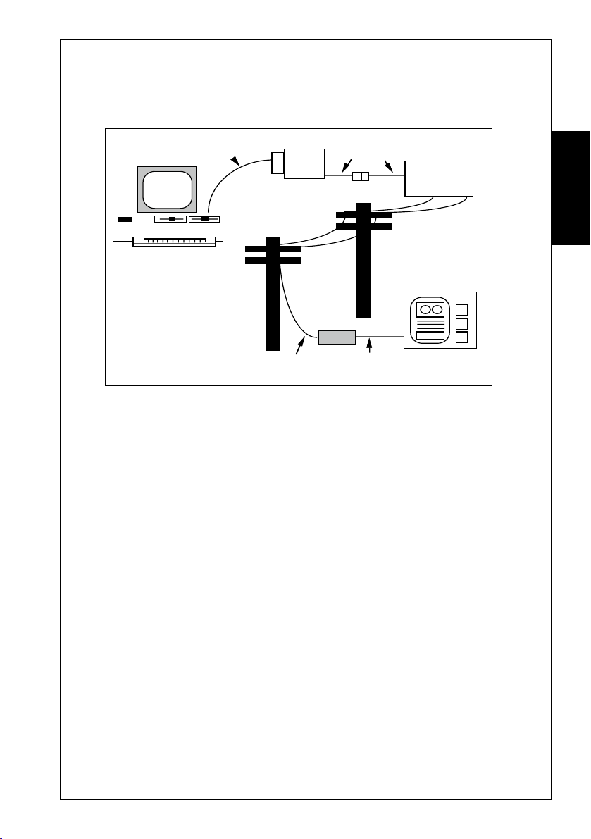
Your Computer
Modem
38400 bps or 19200 bps
with flow control
A typical setup to allow maximum throughput with a V.32 or V.32bis modem.
Command = ATB0\N3%C3 (or %C1) X4 \V1&K3 (or &K4)
9600 bps
☞ Some computers cannot cope with receiving data at speeds
above 19,200 bps. If you wish to run at high speeds, you
should install a COM port that has a 16550 chip in place of
your regular COM port. The 16550 chip allows your
SmartModem Reference Guide

DIGITAL SIMULTANEOUS VOICE &
DATA (Digital SVD)
Digital SVD enables a user to transmit and receive data while
carrying on a voice conversation with the remote user. No
additional controls or commands are needed. The voice and data
streams are separated within the modem and appear to the user
to be operating on different telephone lines.
Digital SVD mode is ON by default but can be turned off using
AT-SSE0 (-SSE1 to turn back on again).
Setting up for Digital SVD
You need to connect a telephone to the connector on the rear of
the modem. The phone connector is the smaller of the two
connectors and you will need an adaptor cable to use it.
Digital SVD
Using the Telephone to make Normal Voice
Connections
❑ You may use your telephone as a normal telephone. Simply
pick up the handset and dial.
❑ On incoming calls the modem will ring instead of the
attached telephone if Digital SVD is enabled. It is not possible
to make the phone ring due to isolation requirements.
❑ If the modem has auto answer turned off (ATS0=0), simply
pick up the telephone and talk.
❑ If S0 is set greater than 0, you need to pick up the telephone
before the specified number of rings or the modem will auto
answer the call and try to start a data connection.
Set S0 to 7 to allow 20 seconds to answer the phone.
SmartModem Reference Guide
Digital Simultaneous
Voice & Data
41

Digital SVD
Starting a Digital SVD Connection after you have
Established a Normal Voice Connection
❑ To start a Digital SVD connection after you have established
a voice connection, either user simply has to type ATD. A
special ringing signal will be generated by the modem
❑ If you are the answering modem you may type ATA to start
the data connection from your side or simply let the modem
count out the number of rings specified by S0 after which it will
auto answer.
❑ The modems will procede with a V.34 handshake and then
enter Digital SVD mode. You may now talk and send data
simultaneously. If either telephone hangs up, the modems will
drop back to data mode (the other telephone will give a call
drop-out indication like a busy tone).
❑ If you wish to re-establish the voice connection simply pick
up the telephone again. If both telephones have hung up, you
may re-establish the voice connection by picking up the
handset. This will cause the other modem to ring.
Voice & Data
Digital Simultaneous
42
❑ If you enter ATH or drop DTR, the data connection will
terminate and you will drop back to normal voice mode. If either
party then hangs up the link will be terminated.
SmartModem Reference Guide

Digital SVD
Starting a Digital SVD Connection after you have
Established a Data Connection
❑ If you have not picked up the handset the modem behaves like
a normal data modem. To establish a data connection issue the
ATD <number> command as per usual.
❑ After the data connection has been established you may open
the voice link by picking up the telephone handset. This will
send a signal to the remote modem that will cause its speaker to
generate a ringing signal.
❑ When the remote user picks up his telephone the voice
channel will be established and you will be in Digitsal SVD
mode.
☞ Digital SVD digitises the voice signal and multiplexes (mixes) it
with the data signal. The data transmission rate will drop while
you are talking. However in periods of silence the data performance
will be almost the same as a non Digital SVD data link.
Digital Simultaneous
Voice & Data
Because of the digitisation process there will be a delay in the voice
signal. This should not be long enough to cause problems.
☞ Since the telephone is powered by the modem the telephone will not
operate if the modem is not powered on. If there is a power failure
remove the phone line from the modem and connect it directly to the
telephone if you wish to receive incoming calls or make outgoing
calls (unless you have a mains powered phone in which case the
phone will not work until the power is restored).
The loudness of the ringing signal can be adjusted via S Register 76.
The pitch of the ringing signal can be adjusted via S Register 77.
SmartModem Reference Guide
43

Security & Encryption
Your modem has many sophisticated security features. They are
discussed in this section. Your modem limits caller access by
means of user names and passwords. User names and passwords
are stored in the modem’s non-volatile memory.
The amount of memory your modem has reserved for this
function depends on the model. The M34F and rack modems
have 20Kbytes whilst other models have 1.2Kbytes. With
typical length user names, passwords and commands over 600
users can be saved in 20Kbytes (40 in 1.2Kbytes)
With each user name and password a modem command of up to
30 characters may be specified. This allows the implementation
of callback to users. Callback is where the modem rings a
specified phone number. Even if an unauthorised caller manages
to break the modem’s security, that caller must be connected to
the phone number specified in the remote modem's database.
SECURITY & ENCRYPTION
Security &
Encryption
44
Also discussed in this section is the topic of DES (Data Encryption
Standard) encryption, which allows you to encrypt data being
passed to a remote modem.
SmartModem Reference Guide

Security & Encryption
The Security Menu
All additions and changes to your modem’s user and password
lists are performed through the Security Menu. This menu is
displayed when you use the #S command.
• Type: AT#S <E>
A prompt will appear: Enter Security Password:
When you first receive your modem, all passwords will be set
as a single ENTER.
• Press the ENTER key
The Security Menu will be displayed:
SECURITY MENU
0 = Quit 1 = List Users
2 = Add or Change Users 3 = Delete All Users
4 = View Access Record 5 = Reset Access Record
6 = Security OFF 7 = Security ON
8 = Change Security Password 9 = Encryption Controls
A = Stored Phone Numbers Displayed B = Supressed
C = Set Password Expiry Days E = Minimum Password Length
D = Download Security File to host U = Upload Security File from
host
L = Encryption Parameters/Keys LOCK F = FREE Encryption and Dial
Enable
K = OutDial Disable M = Dial Stored Phone Numbers Only
Access Security: ON Security Database and Security Mode: FREE
Stored Phone Numbers: SUPRESSED & LOCKED OutDial: STORED NUMBERS ONLY
Enter Security Function:...
Encryption
Security &
Entering a Security Password
You may choose to have a dedicated security password, thus
changing the password assigned for the first security user. To
enter a new security password:
• Select Option 8 from the Security Menu <E>
You will be prompted to enter a new security password. Your
modem is case insensitive. Up to 8 characters may be used,
including spaces.
When you enter your password, each character will appear on the
screen as a # character.
• Type in your new password <E>
You will be prompted to re-enter the new security password.
• Type in your new password again <E>
SmartModem Reference Guide
45

Security & Encryption
Your new password will be stored in your modem’s non-volatile
memory.
Adding and Changing Users
Your modem allows you to add new users and change existing
users. Selecting option 2 on the Security Menu will result in a
prompt:
Enter Name:
To add a new user:
• Type in the name of the new user <E>
User names must not be longer than 30 characters. They are
case insensitive.
To change an existing user:
• Type in the name of the user you wish to change <E>
You will be prompted to enter a new name.
• Type in the new name <E>
• If the user is found you will be given the option to change the
password, delete the user or zero his access counters.
If you are adding a new user or changing a user, you will be
prompted for a new Password (maximum characters = 15).
Security &
Encryption
46
The modem will now prompt you to enter a modem command.
Modem commands consist of up to 30 characters and may
include spaces. When you enter a new command, the previous
command will be overwritten.
☞ Do not include an Attention Code (AT) with your command.
Your modem automatically places an AT at the start of this
command when it is executed.
If you do not want to specify a modem command or want to leave
the current command as it is:
• Press ENTER
If you want to remove the existing command but do not wish to
replace it with another command:
• Press the Spacebar <E>
See details on Callback Security later in this section for more
information about using commands with your user names.
SmartModem Reference Guide

Security & Encryption
Removing Users
Your modem allows you to remove individual users or all the
users currently stored in your modem. To remove an individual
user:
• Select option 2 from the Security Menu
You will be prompted to enter a new user name.
• Type in the name of the user you wish to delete <E>
If the user is found, select the 'D' option to delete.
To delete all the users stored in your modem:
• Select option 3 from the Security Menu
You will be prompted to confirm that you wish to remove all
user names, passwords and commands
• Press Y <E>
Listing Existing Users
To list all user names, and commands.
• Select option 1 from the Security Menu <E>
Your modem will list the user names.
Passwords are never displayed.
Encryption
Security &
☞ Your computer must be capable of displaying at least 80
characters per line for the user list to be displayed in its
correct format.
The Access Record
Selecting option 4 and option 5 from the Security Menu allows
you to view and change the access records. Your modem keeps
a tally of the number of successful (granted) and unsuccessful
(denied) attempts to connect to your modem using each user
name.
Your modem allows every caller three attempts to enter the
correct user name and password. If the caller cannot correctly
enter the password, a record is made by your modem that an
unsuccessful attempt has been made to use that particular user
name.
SmartModem Reference Guide
47

Security & Encryption
If the number of unsuccessful calls for any user name reaches
255, that user name will be locked and callers will no longer be
able to use it, even if the correct password is used. You will not
be able to use that particular user name until the access record
for all users has been reset.
If, however, the caller does correctly enter the password, your
modem records that a successful attempt was made to connect
with that user name.
You should regularly check the number of successful and
unsuccessful attempts to connect to your modem.
• Select option 4 to view the access record <E>
An unusually high number of unsuccessful attempts to connect
with a particular user name may indicate someone is trying to
violate your modem’s security.
Over a period of many months one of the security users may
legitimately accumulate 255 errors, in which case, your modem
will automatically lock that user. If this occurs, select option 2,
enter the user's name and select the Z option to clear his access
record.
Each attempted access with an unknown name increments the
'Invalid Usernames Received' count at the top of the list.
Security &
Encryption
Enabling Modem Security
48
Selecting option 6 or option 7 allows you to disable or enable
your modem’s security mode. With security mode enabled,
whenever your modem answers an incoming call it will demand
the caller enter a user name and password — the following
message will appear on the caller’s computer screen:
Enter Name:
If only one of the modems is configured to use error correction,
there will be a slight delay between the time the modems
connect and when the caller is asked to enter his user name.
SmartModem Reference Guide

Security & Encryption
When the caller enters his name all characters will be displayed
as # characters. The caller is allowed three attempts to correctly
enter his name. Your modem is not case sensitive to user names.
If the caller enters a valid user name, your modem will ask the
caller to enter the password associated with that user name.
Enter Password:
If the caller enters his password correctly, your modem will send
the message ACCESS GRANTED and the caller will have access
to the computer connected to your modem.
If the caller cannot, within three attempts, enter the correct user
name and password, your modem will send the message ACCESS
DENIED and will hang up.
Quitting the Menu
The Quit Security Menu option allows you to return to local
command state from the security menu.
• Press 0 <E>
Your modem will issue an OK message. You will be returned
to local command state.
Encryption
Security &
Callback Security
As mentioned earlier, your modem allows you to specify a
modem command with every user name and password. This
feature allows you to implement modem callback. Callback
means that after a caller has successfully connected, your modem
will hang up and then dial the caller.
Even if an unauthorised caller successfully connects to your
modem, that caller will have to be using the phone line which
your modem is going to call back.
Three commands are required to implement callback. First, you
must hang up your modem with a H command.
SmartModem Reference Guide
49

Security & Encryption
Before your modem can call the caller back, it must wait for the caller’s
modem to hang up and return to local command state. S Register 27
contains a value representing the number of seconds your modem will
wait before commencing dialling. The default value for this register
is 0 — your modem will begin to dial as soon as it receives a dial
command.
It is necessary, therefore, to place another value in S Register 27 to
allow the caller’s modem sufficient time to hang up before your modem
begins to dial. A 30-second delay should be sufficient time to allow
most modems to hang up, so place an S27=30 in the command.
Using a 30-second delay means the telephone exchange, in most cases,
will disconnect the call. This ensures unauthorised callers cannot ‘fool’
callback security by not hanging up after your modem hangs up.
Alternatively, contact your telephone company — some telephone
companies offer an automatic disconnect facility, which assumes a caller
cannot remain off-hook after the modem has hung up.
Place a D command and the caller’s phone number in the command.
Assuming the caller’s phone number is 1234567, you will now have a
command which looks like this:
H S27=95 D1234567
Security &
After the user has been called back and has completed the call, your
Encryption
modem will hang up, automatically issue an ATZ command to restore
all the stored settings and return to local command state, ready to
answer incoming calls.
☞ UK Modems. Telephone exchanges in the UK may not hangup
☞ If security is enabled, the answering modem will not assert DCD
50
after 30 seconds. Consult the supplier of your telephone line for
a possible solution.
or DSR until a valid user name and password are received. If \Q5
is selected, CTS will not be asserted until a valid user name and
password are received.
SmartModem Reference Guide

Security & Encryption
Downloading the Security File
Selecting option 'D' from the security menu will enable a dump
of the security database to your computer for storage or editing.
You will be asked to type 'Y' to start the download.
The file format is:
"<user name>", "<password>", "<command>", nnn, mmm CR
LF where nnn and mmm are the 3 digit Granted and Denied
Access Counts and CR and LF are Carriage Return and Line
Feed.
The last entry has only a CR LF
☞ The download will take place at the current terminal
speed.No flow control is acknowledged. If your computer
cannot accept the file at the current data rate exit security and
autobaud to a lower speed.
Example: "FRED", "NURK", "HS27=30DT3277502", 000,
000 is a valid entry.
Uploading the Security File
Selecting option 'U' from the security menu will enable a
security file in the format described under the Download
command to be uploaded into the modem.
You will first be warned that your existing database will be
overwritten and then told to start uploading the file.
When the upload is finished the modem will return to the
security menu.
The upload will take place at the current terminal speed. The
modem can accept data at 115Kbps.
☞ If the data is not in the correct format, the file can be
corrupted, so edit with care and always keep a copy of the
unmodified download file.
SmartModem Reference Guide
Encryption
Security &
51

Security & Encryption
Your modem supports Data Encryption Standard (DES)
encryption. DES encryption allows you to encrypt data being
passed to a remote modem. The remote modem must support
Cipher Feedback (or CFB) DES encryption in order to decrypt
the data sent from your modem.
The #E1 command is used to select DES encryption.
The modem requires you to enter an encryption Key and an
Initial Value. These are two 16-character hexadecimal numbers.
Both the Key and Initial Value are specified by the user, making
the encrypted data virtually impossible to decrypt without
access to the Key and Initial Value.
Both modems must have DES encryption and error correction
selected and must use the same encryption Key and the same
Initial Value.
Encryption
Security &
Encryption
52
WARNING
Only use a reliable error correction mode when
using DES encryption. This will ensure you will
only establish encrypted connections. Refer to
the \N command (in the Commands sections of
this guide) for details of the reliable error
correction modes supported by your modem.
To enter the DES Key and Initial Value:
• Type: AT#S <E>
If your modem offers security features the Security Menu will
appear (refer to the start of this chapter):
• Type: 9 <E>
You will be prompted with the following message:
Enter Current DES Key
SmartModem Reference Guide

Security & Encryption
If your modem does not offer security features the Security Menu
will not be displayed — you will be prompted to type the
current DES key.
The default DES Key is 16 zeros. If you have not entered a Key
yet:
• Type in 16 zeros <E>
or
• Type in the Key previously stored in the modem <E>
When you enter the Key, each character will appear on your
computer screen as the S character.
After successfully entering the Key, the Encryption Controls
Menu will appear on your screen.
ENCRYPTION CONTROLS MENU
1 = Enter DES Key
2 = Enter DES IV - initial value
0 = Quit
Enter Encryption Function :
The Encryption Controls Menu allows you to alter the Key or IV
(Initial Value).
• Enter the Key and Initial Value as a 16-character hexadecimal
number <E>
You will be prompted to re-enter the Key and Initial Value,
to verify the correct Key and Initial Value has been entered.
You may then return to local command state.
• Select the Quit option from the Encryption Menu
• Select the Quit option from the Security Menu
To enable DES encryption, issue the AT#E1 command. The
next time your modem establishes a connection with another
modem, it will encrypt outgoing data and attempt to decrypt
incoming data.
☞ For countries other than Australia, DES encryption is only
available to end users who meet the security requirements of the
Australian Department of Defence. Contact your modem
supplier for details of making application for a DES equipped
modem to be supplied to you.
SmartModem Reference Guide
Encryption
Security &
53

Security & Encryption
SuperSecure Advanced Security Mode
Some SmartModems now include SuperSecure mode.
SuperSecure mode allows you to :
❑ Have an individual password and an individual DES KEY.
❑ Automatically change the DES key in a random manner after
each connection without the keys ever being knowable.
❑ Have a different password on the answering modem to the
originating modem.
❑ Timed expiry of passwords.
With these new features, a link between two modems will be
very secure. No other modem can dial either modem and
connect because the third party will not know the keys of the
other users, even if both passwords are known.
Security &
Encryption
54
Entering a Key for Each User
• Enter AT#E2 to enable SuperSecure mode
• Select the security menu using AT#S
• Enter the security password to gain access to the security
menu
• Set up the modem's primary DES KEY and Initial Value (IV)
as per standard DES setup
• Select Option 2 to add new users
• Enter the username
• Enter the password to be used by your modem (not necessarily
the same as the password on the modem you are going to dial)
☞ Do not use a / character in any password, because this
character is reserved
• When the modem prompts you for a command, do not enter
a command because you will not be prompted for the DES
KEYS
SmartModem Reference Guide

Security & Encryption
• Enter the 16 hex digit DES secondary KEY for the user, all
16 digits must be keyed
• Enter the 16 hex digit DES secondary Initial Value (IV) for
the user, all 16 digits must be keyed
• Enter the 2 hex digit Key Encryptor (KE) for the user, both
digits must be keyed
☞ The Key, IV and KE can have any value but must be exactly
the same on both answering and orignating modems.
☞ For maximum security do not use keys or initial values that
have easy to remember values.
☞ A KE of 00 turns off random key rotation.
• Enter as many users as you wish whilst in this mode
• Press ENTER at the username prompt to return to the menu
☞ You do not have to turn security on to use SuperSecure. The
#E2 option forces it on always.
Encryption
Security &
• Enter 0 to exit the security menu
☞ The remote modem must not only support SuperSecure but
must also have a matching username/password and KEYS
before access can be gained.
Accessing a System Using SuperSecure
If both your modem and the remote modem have been correctly
setup you can:
❑ Dial the remote system.
❑ The modems will connect and enter security dialog mode
using the modem's primary key.
SmartModem Reference Guide
55

Security & Encryption
❑ This key must be the same for both modems.
• Enter your username
• Press ENTER
• Enter your user password stored in the remote modem then '/'
• Enter your password stored in your modem
• Press ENTER
☞ You may backspace to correct errors but you will not be able
to see what is typed since all characters are echoed as #
• Do not use the / character in any password
• If the password is the same on both modems then only one
password needs to be entered
Connection
❑ You will then CONNECT if the username, both passwords,
all of the KEYS, IVs and KEs match.
Security &
Disconnection
Encryption
56
❑ The data will be correct and error free, but encrypted on the
line using a KEY unknown to anyone.
❑ If the primary DES KEY mis matches you will not be able to
read the "username" prompt.
❑ The modems will disconnect if:
• The secondary key, IV or KE mismatches (you will also
receive a message)
• An error corrected link cannot be established
• Wrong username and/or password is used. You will be
given another two changes to enter them before the modem
disconnects
SmartModem Reference Guide

Security & Encryption
Example:
ATDT 456 4321
RINGING
RINGING
Enter name: MarkStein
Enter password: Fudge/Vanilla
Access granted
• 'Fudge' is Mark Stein's password on the remote system
• 'Vanilla' is the password on the local modem
• 'Access granted' confirms that the passwords are correct
• Secondary keys mismatch if the secondary KEY, IV or KE are
different
Enabling Rotating Secondary Keys
❑ If you enter a KE of 00 for the user, then the secondary key
will remain the same for each connection.
❑ If the KE is not 00 then this value is used as a seed to create
a random new secondary key for the user on each connection.
Encryption
Security &
❑ After the initial connection is made with the KEY, IV and
KE you have entered, these values will change on both modems
to new values which are not accessible by any means.
❑ If an event occurs that corrupts the KEY, IV or KE on either
modem, then both modems will have to be manually set back to
a known starting point.
☞ To ensure random unknown keys, make two connections
between the secure modems after they have been initialised.
SmartModem Reference Guide
57

Security & Encryption
Symmetrical Operation
❑ Either modem can originate the call
❑ Remote modem's password is first.
❑ Local modem's password is second
Automatic Synchronisation
❑ The keys only change after a successful connection is achieved
at both ends.
❑ If either modem drops out during the security handshake
before the CONNECT message, the modems will automatically
resynchronise on the next connection.
Password Expiry Option
You may specify the number of days you have before the password
must be changed. By default this option is OFF, to enable it
select the C option from the security menu. You will then be
prompted for the number of days before a password expires (1255 days). The access record (Option 4) displays the password
age limit and the age of each user's password.
Security &
Encryption
58
❑ When a password is within 5 days of expiry a message will be
given before the connect message.
❑ After the password has expired, you will be informed and will
not be allowed another connection until a new password is
entered.
The access record also notes if you have been informed of the
expiry.
❑ Either the remote or the local password or both may expire.
☞ There is no real time clock inside the modem. When the
modem is turned off the clock stops. Therefore the expiry timers
actually time the number of days that the modem is turned on
and not elapsed days
SmartModem Reference Guide

Security & Encryption
Entering a Password in the Remote Modem's
Database
When connected in SuperSecure, you may change your password.
• Enter **** with a 1 second guard time on either side of the stars
• Enter your current password
• Enter your new password
• Verify your new password
• You will then be returned online
Entering a New Password in the Local Modem's
Database
When connected in SuperSecure, you may change your password
by
• Enter in the escape sequence +++
• Enter in the *S command
• Enter your new password
• Verify your password
• ATO to return online
Encryption
Security &
☞ If you are not online or in the current session of SuperSecure,
you must identify yourself by entering your current username
and password before being able to enter your new password.
Minimum Password Length
You can specify the minimum password length accepted by the
modem by the E option from the Security Menu. Its power-on
default is 3 characters.
Additional User Options
When a new user is entered into the database you will be
SmartModem Reference Guide
59

Security & Encryption
prompted for 'Options' after the password has been entered.
You may key S or E or both, if you do not want either option key
ENTER.
❑ S Specifies that the user is a supervisor and has full
remote access rights to the remote modem.
• If you key **** you will be able to issue almost all AT
commands on the remote modem and access the full security
database if you have the global security password. (See remote
access)
❑ E Your user password does not expire.
• This would be for automated systems that cannot respond to
prompts to enter a new password when it expires
Uploading and Downloading the SuperSecure
Database
Security &
Encryption
60
❑ To ensure the integrity of your modem's security database
the sensitive fields are encrypted with the modem's primary
key. Your password and DES KEYS are scrambled but will be
restored when uploaded into a modem with the same primary key.
❑ You may delete unwanted records and modify the unencrypted
fields, but the encrypted must not be touched.
❑ If you wish to enter a new user, you may do so using the same
format as the other records.
The three digit control field at the start of each record should be
set to the following values for a new user:
000 Not SuperSecure User, no DES keys specified (use for
dialback)
001DES keys specified
003 DES keys specified, Supervisor Status
005 DES keys specified, No password expiry
007 DES keys specified, No password expiry and Supervisor
Status
SmartModem Reference Guide

Security & Encryption
❑ The record format is:
aaa, "<username>", "<encrypted password>", "<command>",
"bbb,ccc,ddd,eee,fff,ggg", "<encrypted key>", "<encrypted> IV",
"<encrypted KE>"CR,LF
• aaa is 3 digit control number
• bbb is 3 digit access granted count
• ccc is 3 digit access denied count
• ddd is 3 digit days since password change
• eee is 3 digit reserved
• fff is 3 digit reserved
• ggg is 3 digit reserved
☞ The control number should not be touched on existing users.
Security Database Lock Option
From the Security Menu you may elect to LOCK the security
database with the 'L' option. When locked, the user cannot
change the #E setting or clear the security database even with the
&F. command or power-on reset with the Mode Switch depressed.
The only way to alter the database or #E selection is to enter the
Security Menu with the security password and unlock the
database with the 'F' (Free) command.
The current state: LOCKED or FREE is displayed below the Security
Menu.
☞ Shorting out the NOVRAM battery will erase the database but
will result in the modem being only partially functional. Such
modems need to be returned to the factory for re-configuration.
Outdial Disable Option
If modems are to be used only for receiving calls option 'K' can
be selected. This does not allow the modem to dial out. If an
attempt to do so, users will be informed that a SECURITY
LOCKOUT is in place and the call will not be successful.
The outdial feature will be useful for system administrators who
SmartModem Reference Guide
Encryption
Security &
61

Security & Encryption
wish to control the use of modems within remote offices or
restrict modems to being used for receiving calls only.
Dial Stored Phone Numbers Only Option
Option 'M' is similar to Option 'K' but restricts the modem to
dialling only those numbers listed in the stored phone number
fields as set with the &Z command.
The stored numbers must then be dialled using the ATDS=X
command where X is the position of the stored number as set
with the AT&Z command.
New stored numbers cannot be added by the user once the dial
restriction has been enabled.
General Notes on Data Security
❑ By using SuperSecure you now have
Security &
Encryption
62
• Ensured that the phone link between two modems is secure
• Ensured that no other user can access either modem when #E2
is enabled
❑ The weak link in the system is now the cable between your
modem and your computer.
• It should be kept visible at all times to prevent wire tapping
• The modem, computer and interconnecting cable should be
physically secure to prevent access
❑ With specialised equipment, the data on the lines and the image
on an screen can be read, due to wires and video screens radiating
radio frequency signals which can be picked up over a distance. You
may need advice on radio frequency screening if this concerns you.
SmartModem Reference Guide

SYNCHRONOUS MODES
This section explains the use of your modem in synchronous
modes. A dumb mode or manual mode allows some of the
functions of your modem to be accessed via the front panel
switches.
Some of the information in this section assumes you have read
the Getting Started Section.
Your modem offers two synchronous modes, conforming to the
Hayes modem synchronous modes 1 and 2. These modes allow
synchronous communication over two-wire PSTN or leased lines
when connected to asynchronous/synchronous computers or
dedicated synchronous terminals.
Synchronous Operation
Your modem supports two synchronous modes. Mode 1 allows
operation with computers which support asynchronous and
synchronous communication on a single RS-232 port. Mode 2
allows your modem to be operated with dedicated synchronous
terminals.
Synchronous Modes
Although your modem can only operate over a single two-wire
connection, it will still perform full-duplex synchronous
communication. Half-duplex operation could be simulated by
controlling the state of the RTS and CTS signals.
Terminal Speeds
Your synchronous terminal or host should use the clock signals
provided by the modem to synchronise transmit and receive
data. The clock speed will represent the actual connection speed
of the modem.
SmartModem Reference Guide
Synchronous
Modes
63

Synchronous Modes
☞ When synchronous mode is selected, your modem cannot
operate in constant speed mode or use the error correction or data
compression facilities of the modem. Only variable speed mode
is available in synchronous connections (this refers to the modem's
terminal speed).
Line Speeds
Your modem supports a number of synchronous line speeds.
Your Command Card lists the line speeds available for your
modem.
When operating in synchronous mode, your modem should
always be configured with a locked, non-auto-ranging B setting
(this refers to modem line speed).
For V.34 or V.FC, the B setting only sets the maximum speed.
The modem will automatically determine the highest usable
speed for the line.
Modes
Synchronous
64
SmartModem Reference Guide

Synchronous Mode 1
i
-li
H
i
i
i
Fai
i
-li
H
i
i
Fai
i
Your modem is capable of dialling remote systems in asynchronous
mode and then automatically switching to synchronous mode
once connection has been made. If the connection is lost, your
modem will hang up and return to asynchronous local command
state.
The computer required to support synchronous communication
with your modem must be capable of switching between
synchronous and asynchronous modes with the same RS-232
Synchronous Modes
Asynchronous
Local Command State
❏
ssued
ATO
❏
ATD issued
DTR Lowered (&D1)
Synchronous
On
ang Up
Asynchronous
Local Command State
on
Connection
shed
Establ
ne State
DTR Lowered (&D0,
&D2) or Remote
er Lost
Carr
Connect
led
❏
ssued
ATA
❏
Incoming Call
DTR Lowered (&D1)
Synchronous
On
ang Up
Synchronous Mode 1 Originate and Answer Modes
Connection
shed
Establ
ne State
DTR Lowered (&D0,
&D2) or Remote
er Lost
Carr
Connect
led
on
Synchronous
Modes
SmartModem Reference Guide
65

Synchronous Modes
port, as well as controlling the state of the DTR signal under
software supervision.
Selecting Synchronous Mode 1
Synchronous mode 1 is selected with the &M1 command.
• Type: AT&M1 <E>
Your modem will enter synchronous mode whenever it
successfully connects to a remote modem.
You should also:
• Type: AT&D2 <E>
This allows hang up via your computer’s DTR signal.
☞ Your computer will not be able to hang up the modem if the
DTR Option Switch is in the DOWN position (DTR will
always be asserted). DTR must be lowered to make the modem
hang up.
To return to asynchronous operation:
• Type: AT&M0 <E>
Modes
Synchronous
66
Dialling
Your computer must be in asynchronous mode before dialling
commences. To begin dialling use the D command. Response
codes sent to the computer depend upon the settings of the X,
V and Q commands. As soon as a connection can be established,
your modem will assert CTS and enter synchronous on-line
state. If connection cannot be made, your modem will hang up
and return to asynchronous local command state.
Character echo and response codes should not be selected when
synchronous communications are used. Use the E0 and Q1
commands to disable character echo and response codes.
As soon as your modem has completed dialling it will examine
SmartModem Reference Guide

Synchronous Modes
the state of the DTR signal. If DTR is asserted your modem will
go on line in synchronous mode, otherwise the modem will hang
up and return to asynchronous local command state.
☞ Data should only be transmitted once DCD, DTR and CTS
have been asserted. Your computer should not assume that if
CTS is asserted then it is safe to begin transmitting data — your
modem will keep CTS asserted whenever it is in local command
state.
Hanging Up
Your modem will hang up and return to asynchronous mode if
carrier is lost for longer than the period defined by S Register 10
or if DTR is lowered after the &D2 command has been issued.
Answering Calls
To automatically answer incoming calls, S Register 0 must be set
to a non-zero value (as with asynchronous auto-answering). Once
a call has been answered there is no means of returning to
asynchronous mode apart from hanging up the modem. This will
occur if the carrier is lost for a period in excess of the time defined
by S Register 0 or if DTR is lowered after the &D2 command has
been issued.
SmartModem Reference Guide
Synchronous
Modes
67

Synchronous Modes
-li
H
i
i
i
Fai
i
-li
H
i
i
i
Fai
i
i
Synchronous Mode 2
Synchronous mode 2 is specifically designed for use
with dedicated synchronous terminals. The phone
number to be dialled is stored in the modem, the
synchronous terminal causing the modem to dial by
asserting the DTR signal.
When the terminal asserts the DTR signal (DTR makes
an OFF-ON transition), your modem will dial stored
phone number zero. The phone number may contain
dial modifiers. See the Command Descriptions chapter
of this guide for details on the &Z command.
Before connecting your modem to your synchronous
terminal, the modem must first be configured using an
asynchronous terminal or computer.
The Sample Setups section of this manual details a
Modes
Synchronous
68
Asynchronous Local
Command State
(Response Codes d
❏
DTR signal asserted
Connection
Establ
Synchronous
ne State
On
DTR Lowered or
Remote Carr
ang Up
Synchronous Mode 2 Originate and Answer Modes
sabled)
shed
Connect
DTR
Low
er Lost
led
Asynchronous Local
Command State
(Response Codes d
on
❏
Incoming Call and
gnal asserted
DTR s
Synchronous
On
ang Up
sabled)
Connection
shed
Establ
ne State
DTR Lowered or
Remote Carr
Connect
DTR
Low
er Lost
on
led
SmartModem Reference Guide

Synchronous Modes
common configuration for synchronous mode 2.
Selecting Synchronous Mode 2
Synchronous mode 2 is selected with the &M2 command.
• Type: AT&M2 <E>
Your modem will enter synchronous mode whenever it
successfully connects to a remote modem.
You should also:
• Type: AT&D2 <E>
This allows you to dial and hang up.
To return to asynchronous mode:
• Type: AT&M0 <E>
Your modem will remain in asynchronous mode.
Dialling
Dialling will commence as soon as the DTR signal is asserted (an
OFF-ON transition occurs). Your modem will not generate
response codes when synchronous mode 2 is selected. All call
progress is indicated by your modem’s speaker (the M command
controls the operation of your modem’s speaker).
As soon as your modem connects to a remote modem it will assert
the DSR and DCD signals.
Hanging Up
Your modem will hang up and return to quiet asynchronous
mode if the carrier is lost for longer than the period defined by
S Register 10 or if DTR is lowered.
Answering Calls
Whenever your modem receives an incoming call it will assert
the RI signal. The terminal may accept the call by asserting the
DTR signal as soon as the number of rings defined by S Register
0 is reached. The terminal may refuse the call by keeping DTR
low eight seconds after the number of rings in S Register 0 is
reached.
Your modem will not dial the stored number in response to DTR
SmartModem Reference Guide
Synchronous
Modes
69

Synchronous Modes
LEASED LINE OPERATIONS
A leased line, or private line, is a telephone line that permanently
connects two or more locations. The leased line does not have
any switching equipment associated with it.
Leased-line operation with the modem is selected with the &L
command.
The &L command informs your modem that communications
will occur over leased lines, with no answer tones being generated
by the modem. If the modem detects a loss of the remote carrier
signal while leased-line operation is selected, it will attempt to
re-establish the connection rather than hang up.
If you select leased line operation with the &L1 command, you
must issue the ATA command to answer a call, and the ATD
command to initiate a call.
If you use &L2 or &L3 to select Auto leased line operation, you
do not need to issue the ATA or ATD commands; &L2 selects
Originate mode automatically and &L3 selects Answer mode
automatically. To dial or answer, raise DTR; to return to local
command state, lower DTR.
Modes
Synchronous
70
☞ You will require a special phone cable (available from your
dealer) to connect your modem to a leased-line socket. The
phone cable supplied with your modem is suitable for use with
normal, dial-up, voice (PSTN) lines.
Before commencing leased-line communications, it is
recommended that a non-auto-ranging B setting be specified.
☞ If error correction is required, select a Reliable mode, not an
Auto-Reliable mode. (See the \N command.)
Auto-ranging and fallback are disabled in leased-line mode.
Your modem will only attempt to connect using the
communications standard specified by the B command and the
SmartModem Reference Guide

i
ff-
i
i
1) -
-
-
i
terminal speed.
Once a connection has been established, if your modem detects
a loss of carrier it will continuously attempt to re-establish the
connection.
Smart Leased- Line Mode
Leased-line operation is available in both asynchronous and
synchronous mode 1.
Asynchronous Local
DTR lowered (&D2)
DTR lowered
Command State
ATD or ATA
ssued
Key Pressed
ATH issued or Carrier Lost - Async only
Synchronous Modes
Sync only
Async only
Async only
Attempt to
sh Connection
Establ
Carrier
Lost
On-line State
ATO
ssued -
O
hook
Asynchronous Local
Command State
Connection
sh
Establ
Escape Sequence
or DTR lowered
Async mode
(&D
Synchronous
Modes
Smart Leased-Line Mode (&L1)
Calling and AnsweringUsing &L1
When operating in smart mode (&L1 set), the ATD and ATA
commands are used to initiate and answer calls respectively.
☞ Your modem will hang up and return to local command state
if your computer transmits characters while the modem is
attempting to establish or re-establish a connection (unless
&N0 has been issued).
SmartModem Reference Guide
71

Synchronous Modes
Auto Leased Line Operation (&L2 or &L3)
You can select Auto leased line operation with the &L2 or &L3
command. In Auto leased line operation you do not need to issue
the ATA command to answer a call, or the ATD command to
initiate a call. Issue the &L2 command to automatically select
Originate mode, or the &L3 command to automatically select
Answer mode.
In Auto leased line operation AT commands can only be entered
while DTR is low. Irrespective of the &D setting, your modem
will remain in idle mode when DTR is low, and will go on-line
when DTR is high and the modem’s TALK/DATA switch is set
to DATA. If DTR is lowered (or the TALK/DATA switch is set
to TALK) when your modem is on-line, it will hang up and
return to idle mode. If power is lost, your modem will enter online state when DTR is restored.
☞ Your communications software must be capable of altering
the state of the DTR signal to work successfully with the &L2
and &L3 commands. If your modem has a TALK/DATA
switch, it must be set to DATA.
Modes
Synchronous
72
Hanging Up
There are four ways of hanging up your modem when leased-line
mode is selected.
❏ If your modem is attempting to establish or re-establish a
connection, sending characters to it will cause it to hang up
(unless &N0 has been issued).
❏ If synchronous mode is selected, lowering the DTR signal
will cause your modem to immediately hang up.
❏ If asynchronous mode is selected, issuing the ATH command
will cause the modem to hang up.
❏ If asynchronous mode is selected (&L2 or &L3), lowering
DTR will cause the modem to hang up.
❏ Switch the TALK/DATA switch to TALK.
SmartModem Reference Guide

☞ XON/XOFF flow control should not be selected for leased-
line connections. Your modem will prematurely hang up if your
computer sends an XON/XOFF character while the modem is
attempting to re-establish a connection.
Improving the Reliability of Leased-Line
Connections
If you are experiencing data errors over leased lines, issue the %L
command to lower the transmit level of your modem.
You may need to experiment with the levels, but start between
%L15 and %L19.
The transmit level should be changed on both modems.
Synchronous Modes
SmartModem Reference Guide
Synchronous
Modes
73

Dumb Mode
DUMB MODE OPERATION
Your modem has two methods of operating with your computer.
The commonly used method is “smart mode”, where the computer
issues “AT” commands to the modem to make it dial and hang
up
For computers which do not offer an asynchronous port or cannot
communicate synchronously using V.25bis commands, dumb
mode permits manual control of your modem.
Selecting Dumb Mode on Desktop Modems
To select Dumb mode:
• Place front panel Option switch 4 in the Down position
To select Smart mode:
• Place front panel Option switch 4 in the Up position
Dumb Mode
74
The Option Switches and Mode and Talk/Data buttons
Some modems also have rear panel Option switches — check the
rear panel of your modem.
HINT:
To restore the factory settings of your modem, switch it on
holding the Mode button in, until the modem “beeps” twice.
SmartModem Reference Guide

Dumb Mode
Selecting Dumb Mode on ProRack Modems
To select Dumb mode on a ProRack modem:
• Place front panel Option switch 6 in the On (or Left) position
To select Smart mode:
• Place front panel Option switch 6 in the Off (or Right)
position
ProRack Modem Option Switches
Setting Up your Modem
In most instances, your modem will need to be configured prior
to entering Dumb mode. All configuration of your modem is
performed using the AT commands.
For example, if you wish to have your modem dial a stored
telephone number when the computer asserts (or “raises”) the
DTR signal, you must first store the telephone number in the
modem and select stored number dialling operation, using the
AT commands.
SmartModem Reference Guide
Dumb Mode
75

Dumb Mode
Selecting Communications Speeds on
Desktop Modems
If you are dialling in Dumb mode, the communication speed it
uses is dependant upon the setting of the front panel Mode
LEDs.
To change the speed at which your modem connects after
dialling:
• Place front panel Option switches 3 and 4 in the Down
position (disable auto-answering, select Dumb mode)
• Press the Mode button (located next to the front panel
Option switches) until the correct speed is indicated on the
front panel Mode LEDs
☞ Your modem cannot dial if auto-answer is enabled.
Refer to the table printed in your modem Installation Guide - it
shows the meaning of each combination of the Mode LEDs.
Dumb Mode
76
To change the speed at which your modem connects after
answering an incoming call:
• Place front panel Option switch 4 in the Up position (select
Smart mode)
• Connect your modem to a personal computer — refer to the
modem Installation Guide for details
• Run a communications program (such as Cooee or
MicroPhone) and enter “local mode” or “terminal mode”
• Type: ATBx&W <E>
where “x” is a valid setting of the B command. For example,
ATB13&W selects V.32 (9600 bps) mode.
The B command is used to set the communications standard
used by your modem.
SmartModem Reference Guide

Selecting Communications Speeds on
ProRack Modems
If you are dialling in Dumb mode, the communication speed it
uses is dependant upon the setting of the front panel Mode
LEDs.
To change the speed at which your modem connects after
dialling
• Place front panel Option switches 5 and 6 in the On (or Left)
position to select Dumb mode and disable auto-answer
• Press the Mode button until the correct speed is indicated on
the front panel Mode LEDs
☞ Your modem cannot dial if auto-answer, verify this is enabled.
Refer to the table printed in your modem Installation Guide —
it shows the meaning of each combination of the Mode LEDs.
Dumb Mode
To change the speed at which your modem connects after
answering an incoming call:
• Place front panel Option switch 6 in the Off (or Right)
position to select Smart mode
• Connect your modem to a personal computer — refer to the
modem Installation Guide for details
• Run a communications program (such as Cooee or
MicroPhone) and enter “local mode” or “terminal mode”
• Type: ATBx&W <E>
where “x” is a valid setting of the B command. For example,
ATB13&W selects V.32 (9600 bps) mode.
The B command is used to set the communications standard
used by your modem.
SmartModem Reference Guide
Dumb Mode
77

Dumb Mode
Hints for Unix Computers and Multiplexers
Many Unix computers and multiplexers which offer synchronous
communications ports cannot cope with the response messages
generated by the modem. For this reason, you may wish to switch
off response messages before you connect your modem to the
Unix computer or multiplexer.
• Place front panel Option switch 4 in the Up position to select
Smart mode
For ProRack modems, place switch 6 in the Off (or Left)
position.
• Connect your modem to a personal computer, a Unix computer
or a serial server — refer to the modem Installation Guide for
details
• Run a communications program (such as Cooee or MicroPhone
for Windows, or TIP or CU for Unix) and enter “local mode”
or “terminal mode”
• Type: ATE0Q1&N0&W <E>
• Exit the communications program
Dialling in Dumb Mode
Dumb Mode
78
This command switches off response messages and character
echo, causes the modem to ignore characters sent to it from the
host while dialling or answering, and saves the changes in the
modem.
There are three ways of dialling in dumb mode:
❏ Use a telephone handset connected to the modem.
❏ Store a telephone number in the modem and then have the
computer raise the DTR signal.
❏ Store a telephone number in the modem and then press the
Talk/Data switch.
☞ ProRack modems can dial only by raising the DTR signal to
dial a stored telephone number.
SmartModem Reference Guide

Dialling with a Telephone Handset
Manual dialling requires a telephone handset to be connected to
the same phone line as your modem. Use a telephone cable with
a double adaptor socket to connect your modem and telephone to
the same phone line
This form of dumb-mode dialling is not supported by ProRack
modems.
• Set up your modem in “smart mode”, using the AT commands.
• Place front panel Option switch 4 in the Down position
(select Dumb mode)
• Place front panel Option switch 6 in the Down position
(select Originate mode)
• Place front panel Option switch 3 in the Down position
(disable auto-answering)
☞ Your modem cannot dial if auto-answer is enabled.
• If necessary, use the Mode button to select the required
communication speed
Dumb Mode
The connection speed of the modem is indicated by the Mode
LEDs. Refer to the table printed in your modem Installation
Guide - it shows the meaning of each combination of Mode
LEDs.
• Press the Talk/Data button to Talk (this button is located
next to the front panel Option switches)
• Using the telephone handset, dial the number
• As soon as the other modem answers your call, press the Talk/
Data button to Data
If the AT&D2 command has been issued prior to entering Dumb
mode, your computer must raise the DTR signal before you press
the Talk/Data button.
• Place the handset on-hook
The OH and CD LEDs glow when the modem connects.
To hang up:
• Press the Talk/Data button to Talk
SmartModem Reference Guide
Dumb Mode
79

Dumb Mode
Using the Talk /Data Button to Dial
You may commence dialling by pressing the Talk/Data button,
located next to the front panel Option switches. By dialling in
this manner, you do not need to use a telephone handset.
This form of dumb-mode dialling is not supported by ProRack
modems.
• Place front panel Option switch 4 in the Up position (select
Smart mode)
• Connect your modem to a personal computer — refer to the
modem Installation Guide for details
• Run a communications program (such as Cooee or MicroPhone)
and enter “local mode” or “terminal mode”
• Type: AT&Z0=phoneno <E>
Where “phoneno” is the telephone number you want your
modem to dial. This command stores the number as stored
telephone number zero.
☞ If you are using your modem over leased lines, do not store a
phone number.
Dumb Mode
80
• Type: AT&D2&M4 <E>
or:
Type: AT&D2E0Q1&M2 <E>
Issue the &M4 command if you wish to use asynchronous
communications; issue &M2 if you wish to use synchronous
communications.
• Type: AT&W <E>
The modem set up is saved.
• Place front panel Option switch 4 in the Down position
(select Dumb mode)
• Place front panel Option switch 6 in the Down position
(select Originate mode)
• Place front panel Option switch 3 in the Down position
(disable auto-answering)
☞ Your modem cannot dial if auto-answer is enabled.
SmartModem Reference Guide

Dumb Mode
• If necessary, use the Mode button to select the required
communication speed
The connection speed of the modem is indicated by the Mode
LEDs. Refer to the table printed in your modem Installation
Guide; it shows the meaning of each combination of Mode LEDs.
• Raise the DTR signal on your computer
If your modem has a TR front panel LED, it glows when DTR
is raised.
• Press the Talk/Data button to Data
The Talk/Data button must be changed from Talk to Data to
cause the modem to dial.
Your modem dials stored telephone number zero. The OH and
CD LEDs glow when the modem connects.
To hang up:
• Have your computer lower the DTR signal or press the Talk/
Data switch to Talk
Using DTR to Dial
You may commence dialling by having your computer raise its
DTR signal.
• Place front panel Option switch 4 in the Up position (select
Smart mode)
For ProRack modems, place switch 6 in the Off (or Right)
position.
• Connect your modem to a personal computer — refer to the
modem Installation Guide for details
• Run a communications program (such as Cooee or
MicroPhone) and enter “local mode” or “terminal mode”
• Type: AT&Z0=phoneno <E>
Where “phoneno” is the telephone number you want your
modem to dial. This stores the number as stored telephone
number zero.
☞ If you are using your modem over leased lines, do not store a
phone number.
SmartModem Reference Guide
Dumb Mode
81

Dumb Mode
• Type: AT&D2&M4 <E>
or:
Type: AT&D2&M2 <E>
Issue the &M4 command if you wish to use asynchronous
communications; issue &M2 if you wish to use synchronous
communications.
• Type: AT&Wn <E>
The modem set up is saved to profile n=0-3
• Place front panel Option switch 4 in the Down position
(select Dumb mode)
For ProRack modems, place Option switch 6 in the On (or
Left) position.
• Place front panel Option switch 6 in the Down position
(select Originate mode)
For ProRack modems, place Option switch 8 in the On (or
Left) position.
• If necessary, use the Mode button to select the required
communication speed
Dumb Mode
82
The connection speed of the modem is indicated by the Mode
LEDs. Refer to the table printed in your modem Installation
Guide; it shows the meaning of each combination of Mode LEDs.
• Press the Talk/Data button to Data (this button is located
next to the front panel Option switches)
ProRack modems do not have a Talk/Data button; they are
permanently set to “Data”.
• Raise the DTR signal on your computer
DTR must change from “low” to “high” to commence dialling.
Your modem dials the stored telephone number zero. The OH
and CD LEDs glow when the modem connects.
To hang up:
• Have your computer lower the DTR signal, or press the
Talk/Data button to Talk
SmartModem Reference Guide

Answering Calls in Dumb Mode
Your modem is able to answer incoming calls, automatically or
by manual intervention.
Automatic Answering
Your modem is able to auto-answer incoming calls in Dumb
mode. You do not need a telephone handset to have your modem
answer incoming calls.
• Place front panel Option switch 4 in the Up position (select
Smart mode)
For ProRack modems, place Option switch 6 in the Off (or
Right) position.
• Connect your modem to a personal computer — refer to the
modem Installation Guide for details
• Run a communications program (such as Cooee or
MicroPhone) and enter “local mode” or “terminal mode”
• Type: ATBx <E>
where “x” is a valid setting of the B command. The B
command is used to set the communications standard used by
your modem.
• Type: AT&D2&M0 <E>
or:
Type: AT&D2E0Q1&M1 <E>
Dumb Mode
Issue the &M0 command if you wish to use asynchronous
communications; issue &M1 if you wish to use synchronous
communications.
• Type: AT&W <E>
The modem set up is saved.
• Place front panel Option switch 4 in the Down position
(select Dumb mode)
For ProRack modems, place Option switch 6 in the On (or
Left) position.
• Place front panel Option switch 6 in the Up position (select
Answer mode)
SmartModem Reference Guide
Dumb Mode
83

Dumb Mode
For ProRack modems, place Option switch 8 in the Off (or
Right) position.
• Place front panel Option switch 3 in the Up position (allow
auto-answering of incoming calls)
For ProRack modems, place Option switch 5 in the Off (or
Right) position.
If the &D2 command has been issued to the modem, DTR must
be raised by your computer.
• Press the Talk/Data button (located next to the front panel
Option switches) to Data
ProRack modems do not have a Talk/Data switch; they are
permanently set to “Data”.
Your modem answers incoming calls after the number of rings
specified in S Register 0.
Manual Answering
For reasons of data security, it may be desirable to verbally
identify a caller before allowing connection to your computer. A
telephone handset must be connected to the same telephone line
as your modem to permit manual answering — refer to your
modem Installation Guide for details of connecting a telephone
handset.
Dumb Mode
84
This form of dumb-mode answering is not supported by ProRack
modems.
• Place front panel Option switch 4 in the Up position (select
Smart mode)
• Connect your modem to a personal computer — refer to the
modem Installation Guide for details
• Run a communications program (such as Cooee or
MicroPhone) and enter “local mode” or “terminal mode”
• Type: ATBx <E>
where “x” is a valid setting of the B command. The B
command is used to set the communications standard used by
your modem.
SmartModem Reference Guide

Dumb Mode
• Type: AT&D2&M0 <E>
or:
Type: AT&D2&M1 <E>
Issue the &M0 command if you wish to use asynchronous
communications; issue &M1 if you wish to use synchronous
communications.
• Type: AT&W <E>
The modem set up is saved.
• Place front panel Option switch 4 in the Down position
(select Dumb mode)
• Place front panel Option switch 6 in the Up position (select
Answer mode)
• Place front panel Option switch 3 in the Down position (stop
auto-answering of incoming calls)
If the &D2 command has been issued to your modem, your
computer must raise the DTR signal
• Press the Talk/Data button to Talk (this button is located
next to the front panel Option switches)
• When the telephone handset rings, pick it up and establish
the caller identity
The person calling you must perform a manual dial (that is, he/
she must dial using a telephone handset).
• When you are ready to allow access to your computer, press
the Talk/Data button to Data
• Place the handset on-hook
At the same time, the caller must make his/her modem enter
“data mode” and place his/her handset on-hook. (Refer to Dialling
with a Telephone Handset section)
The OH and CD LEDs glow when the modems connect.
SmartModem Reference Guide
Dumb Mode
85

Dumb Mode
The Option Switches
The Option switches allow you to control the operation of your
modem in Dumb mode, as well as providing additional features
in Smart mode.
This section explains the use of Option switches for desktop
modems (with or without rear panel Option switches) and
ProRack modems.
Modems with Rear Panel Option Switches
If your modem has rear panel Option switches, these functions
are available:
Description Switch
DSR acts normally Sw 1 - Up
DSR mimics DTR Sw 1 - Down
DTR controlled by the computer Sw 2 - Up
DTR is assumed to be asserted Sw 2 - Down
DCD is asserted after a connection Sw 4 - Up
DCD is always asserted Sw 4 - Down
Dumb Mode
86
The operation of the front panel option switches is identical to
desktop modems without rear panel option switches. Refer to
Modems without Rear Panel Option Switches section.
NOTE:
For users of modems with front and rear panel switches
• Rear panel Option switches always take precedence over front
panel Option switches.
For users of modems with front panel Option switches only
• Front panel Option switches 1 and 2 always take precedence
over software setting of behaviour of DTR and DSR. When
AT%F is set to 1 (when AT%F is set to 0, behaviour of DTR
and DSR is controlled by AT commands if applicable).
SmartModem Reference Guide

Modems without Rear Panel Option Switches
Switches 1 and 2 are used to select AT command mode or
V.25bis command mode, or control the state of the DTR and
DSR signals.
Description AT%F Switch 1 Switch 2
AT command mode %F0 Up Up
V.25bis asynchronous %F0 Up Down
V.25bis synchronous (HDLC framing) %F0 Down Up
V.25bis sync (BSC character framing) %F0 Down Down
DTR controlled by computer %F1 Up n/a
DTR assumed to be asserted (raised) %F1 Down n/a
DSR acts normally %F1 n/a Up
DSR mimics DTR %F1 n/a Down
☞ n/a = not applicable
Switches 3 - 6 allow you to set up Dumb mode operation, as well
as manually selecting loopback tests in Smart mode.
Description AT#F Switch Switch
Smart mode n/a 4 - Up n/a
Dumb mode n/a 4 - Down n/a
Loopback Test Pattern Off #F1 3 - Up 4 - Up
Loopback Test Pattern On #F1 3 - Down 4 - Up
Analog Loopback Off #F1 5 - Up 4 - Up
Analog Loopback On #F1 5 - Down 4 - Up
Remote Digital Loopback Off #F1 6 - Up 4 - Up
Remote Digital Loopback On #F1 6 - Down 4 - Up
Auto-answer enabled n/a 3 - Up 4 - Down
Auto-answer disabled n/a 3 - Down 4 - Down
Asynchronous operation n/a 5 - Up 4 - Down
Synchronous operation n/a 5 - Down 4 - Down
Answer mode n/a 6 - Up 4 - Down
Originate mode n/a 6 - Down 4 - Down
Dumb Mode
Dumb Mode
☞ n/a = not applicable
SmartModem Reference Guide
87

Dumb Mode
ProRack Modems
ProRack modem offer the following front panel Option switches:
Description Switch
Auto-answer enabled 5 - Off (Right)
Auto-answer disabled 5 - On (Left)
Smart mode 6 - Off (Right)
Dumb mode 6 - On (Left)
Asynchronous operation 7 - Off (Right)
Synchronous operation 7 - On (Left)
Answer mode 8 - Off (Right)
Originate mode 8 - On (Left)
V.25bis mode is selected with Option switches 3 and 4:
Description Switch 3 Switch 4
AT command mode Off (Right) n/a
V.25bis synchronous (HDLC framing) On (Left) Off(Right)
V.25bis sync (BSC character framing) On (Left) On (Left)
Dumb Mode
88
SmartModem Reference Guide

CCITT V.25bis OPERATIONS
V.25bis is a modem command set specified by the CCITT. Like
the AT command set, it allows you to control your modem.
However, V.25bis commands may be issued to the modem in
asynchronous or synchronous mode (AT commands may only be
issued when the modem is operating in asynchronous mode).
This means V.25bis is suitable for mainframe and minicomputers
which only support synchronous communications ports. The
implementation of V.25bis supported by your modem is based
upon the 1988 revision of the V.25bis specification, however not
all aspects of the V.25bis specification have been implemented.
☞ V.25bis operation is supported in both smart and dumb
modes.
Selecting V.25bis Operation
V.25bis Operations
To select V.25bis mode, issue the appropriate #M command.
Three V.25bis modes are supported by your modem:
❏ Asynchronous V.25bis. The modem operates in asynchronous
mode using V.25bis command rather than AT commands.
Issue the AT#M1 command to select this mode.
❏ Synchronous V.25bis with HDLC framing. The modem
communicates and accepts V.25bis commands in synchronous
mode with HDLC framing. Issue the AT#M2 command to
select this mode.
❏ Synchronous V.25bis/BSC mode. The modem communicates
and accepts V.25bis commands in synchronous mode with
character framing (BSC mode). Issue the AT#M3 command
to select this mode.
SmartModem Reference Guide
Operations
V.25bis
89

V.25bis Operations
The &W and Z commands must be issued after the #M command
in order for V.25bis command mode to be selected. Alternately,
issue the &W command after the #M command and switch the
modem off and on or lower DTR (after an &D3 command has
been issued).
☞ When you reset the modem (for example, you issue the &F
If your modem has Option switches to select V.25bis operation,
the setting of the Option switches always take precedence over
the #M command.
The %R2 option will be required for most V.25bis setups. This
setting ensures that the CTS signal is only asserted when the
modem is ready to accept a new command (in command mode).
command or issue the RST command or switch the modem
off and on), you must issue an ATZ command to select
V.25bis command mode; your modem always resets and
powers-up in AT command mode, regardless of the setting of
the #M command.
V.25bis
Operations
90
Overridden Settings
Almost all AT commands and S Registers stored before entering
V.25bis mode will have effect except for the following commands.
AT Command V.25bis Operation
&D Will act as if &D2 is selected
S0 Will act as if S0=1
These override settings are not stored in your modem’s nonvolatile memory; they are active only while V.25bis command
mode is active. If you issue the &V command to view the
modem’s configuration the original settings will be displayed.
SmartModem Reference Guide
 Loading...