

Octek Panther-II User Manual

'--------------~--------~"--
J
I
"iJ
J
"'
t
C
(
I
~~<'
010
t
il
-------~-------------
--
-------
PANT.Ea-11
31'SX
h~idl.le
ai
bus
'(Ino
noitam'lolni
101 ai
Isunsffi
ailH
fli
l4!iutsm
sdT
"9:>"'Ofl
;tuorliiw samui:>
0.1
1.1 :
K&III"¥"
;Xllo1t1l<,
,XtioW
,r\eo
,80G-8
...
,80<1-:)"1
,TA\TX\G"I
NSf
,1iIHtI
IIK'f
aJU
&K
baa
aat
,Xaal£
,"1'111
,20lS
IMA
.&otfl
..
Jll:'l~T.
'1<>
S>lilAMa"GA.iIT
{!{JtjfrreH):'IH
HO
aX.A._Gd"
aSfStfWO
S'Vf1'~3CJ81!UI

RADIO
FREQUENCY
INTERFERENCE
STATEMENT
This
equipment
frequency
energy
properly,
that
is,
generates
and
uses
radio
and
if
not
installed
and
used
in
strict
accordance
with
the
manufacturer's
instructions,
may
cause
interference
with
radio
and
television
reception.
If
this
equipment
does
cause
interference
to
radio
or
TV
reception,
which
can
be
determined
by
turning
the
equipment
off
and
on,
the
user
IS
encouraged
to
try
to
correct
the
interference
by
one
or
more
of
the
following
measures
*
*
*
*
*
*
*
Reorient
the
receiving
antenna.
Relocate
the
computer a way
from
the
recei
ver.
Move
the
computer
away
from
the
receiver.
Plug
the
power
cord
of
computer
into
a
different
outlet
so
that
computer
and
receiver
are
on
different
branch
circuits.
Ensure
that
card
slot
covers
are
in
place
when
no
card
is
installed.
Ensure
that
card
mounting
screws,
attachment
connector
screws,
and
ground
wires
are
tightly
secured.
If
peripherals
are
used
with
this
system,
it
is
suggested
to
use
shielded,
grounded
ca
bles,
with
in-line
filters
if
necessary.
If
necessary,
the
user
should
consult
the
dealer
service
representative
for
additional
suggestions.
The
manufacturer
is
not
responsible
for
any
radio
or
TV
interferences
caused
by
unauthorized
modifications
to
this
equipment.
It
is
the
responsibility
of
the
user
to
correct
such
in
terferences.

The
material
in
this
manual
is
for
information
only
and
is
subject
to
change
without
notice.
REVISION:
1.1
IBM,
IBM
PC/XT/AT,
PC-DOS,
MS-DOS,
OS/2,
UNIX,
XENIX,
MR
BIOS,
AMI
BIOS,
INTEL,
386SX,
386
and
286
ARE
THE
TRADEMARKS
OR
REGISTERED
TRADEMARKS
OF
THEIR
RESPECTIVE
OWNERS.
o c

OPERA
TION
AND
MAINTENANCE
KEEPING
THE
SYSTEM
COOL
Airflow
is
critical
for
proper
operation.
The
motherboard
contains
many
high-speed
components
and
they
will
generate
heat
during
operation.
Other
add-on
cards
and
hard
disk
drive
can
also
produce a lot
of
heat.
As a result,
the
temperature
inside
the
computer
system
may
be
very
high.
These
boards
require
cool
air
to
prevent a deadly
heat
build-up.
Be
sure
that
all
cooling
vents
in
the
front
or
sides
of
the
computer
are
open
and
that
air
circulation
is
good.
Check
the
clearance
at
the
back
of
the
computer;
the
power
supply
contains a fan
to
blow
air
out
of
the
case,
make
sure
the
fan
is
not
blocked
by
cables
or
papers.
Don't
push
your
computer
flush
against
the
wall;
leave
it
some
breathing
space.
Heat
can
destroy
compu
ter
ch
ips.
CLEANING
THE
"GOLDEN
FINGER"
Whenever
inserting
an
add-on
card
to
the
motherboard,
make
sure
that
there
is
no
dirt
on
the
"golden
finger"
of
the
add-on
card.
If
not,
the
contact
between
the
"golden
finger"
and
the
slot
may
be
poor
and
thus
causing
the
add-on
cards
to
work
improperly.
Use a pencil
eraser
to
clean
the
"golden
finger"
if
dirt
is
found.
B-2
C:
CONTENT
Chapter
1
INTRODUCTION
Chapter
2
GENERAL
FEATURES
Specification
Processor
Ma
th
Coprocessor
Memory
System
I/O
Subsystem
System
Functions
I - I
2-1
2-
1
2-3
2-6
2-8
2-11
2-12
Chapter
3
INSTALLING
COMPONENTS
3-1
Installing
80387SX
Math
Coprocessor
3-1
System
Memory
Configuration
3-3
Control
of
System
Speed
3-8
System
Board
Jumper
Setting
3-10
System
Board
Connectors
3-11

Chapter
4
TECHNICAL
INFORMATION
4-1
Memory
Mapping
I/O
Address
Map
System
Timers
System
In
terrupts
Direct
Memory
Access
COMA)
Real
Time
Clock
and
CMOS
RAM
CMOS
RAM
Address
Map
Real
Time
Clock
Information
System
Expansion
Bus
APPENDIX
A
SYSTEM
BIOS
Self-Test
System
Setup
APPENDIX
B
OPERATION & MAINTENANCE
Keeping
the
System
Cool
Cleaning
the
"Golden
Finger"
Cleaning
the
Motherboard
APPENDIX C SYSTEM
BOARD
LAYOUT
4-1
4-2
4-4
4-6
4-7
4-9
4-10
4-11
4-12
A-I
A-I
A-4
8-1
B-2
B-2
B-3
C-I
Appendix B
Operation and Maintenance
Some
components
of
the
Panther-II
or
computer
components
are
static-sensitive
devices
and
can
be
damaged
by
static
discharges.
To
prevent
such
damage,
the
device
may
be
wrapped
in
a
conductive,
anti-static
bag;
certain
precautions
should
be
taken
before
removing
the
dev
ice
from
its
bags.
When
installing
or
removing
any
add-on
card,
DRAM
module
or
coprocessor,
care
should
be
taken
when
handling
these
devices.
Touch
an
unpa
in t metal
pa
rt
of
you r system
un
i t
Cf
or
example,
the
screws
on
the
rea r of
the
system
unit)
with
one
hand,
then
hold
the
component
you
are
installing
on
the
other
hand.
This
will
place
your
body,
the
component,
and
the
system
unit
at
the
same
ground
potential.
preventing
an
accidental
static
discharge.
Be
sure
to
handle
circuit
boards
by
the
edges
only
and
do
not
touch
the
component
pins
or
solder
joints.
Grasp
diskette
drives
or
fixed
disk
drives
by
their
frames
to
avoid
touching
the
circuit
board.
Memory
chips
or
co-processor
should
be
held
by
their
bodies
only,
not
by
their
pins.
Preventing
a
problem
is
better
than
having
to
fix
it
after
it
has
happened.
This
is
where
cleanliness
and
proper
operating
procedures
come
into
play.
8-1

OPERATION
AND
MAINTENANCE
CLEANING
THE
MOTHERBOARD
Because
the
system
is
air-cooled,
dust
can
enter
your
system
through
the
ventilation
slots.
At
least
once a year,
take
the
cover
off
your
computer
and
vacuum
the
interior
to
remove
accumulated
dust.
Use a brush
attachment
on
the
vacuum
and
carefully
go
over
all
exposed
parts.
To
prevent
dust
from
accumulating
on
the
mother-
board,
installing
all
mounting
plates
on
the
rear
of
the
case.
Regularly
examine
your
system,
and
if
necessary,
vacuum
the
interior
of
the
system
with a miniature
vacuum.
B-3

TECHNICAL
INFORMATION
SYSTEM
INTERRUPTS
Sixteen
levels
of
system
interrupts
are
provided
on
Panther-II.
The
following
shows
the
interrupt-level
assignments
in
decreasing
priority.
Level
Microprocessor
NMI
Interrupt
Controllers
CTLR
1
IRQO
IRQI
IRQ2
-
IRQ3
IRQ4
IRQ5
IRQ6
IRQ7
4-6
CTLR
2
-
IRQ8
IRQ9
-
IRQIO
IRQII
IRQI2
IRQI3
IRQI4
IRQI5
~
Function
Parity
or
I/O
Channel
Check
Timer
Output
0
Keyboard
(Output
Buffer
Full)
Interrupt
from
CTLR
2
Real-time
Clock
Interrupt
Software
Redirected
to
INT
OAH
(lRQ2)
Reserved
Reserved
Reserved
Coprocessor
Fixed
Disk
Controller
Reserved
Serial
Port
2
Serial
Port
I
Parallel
Port
2
Diskette
Controller
Parallel
Port
I
TECHNICAL
INFORMATION
DIRECT
MEMORY
ACCESS
(DMA)
Panther-II
supports
seven
DMA
channels.
I
Channel
I
Function
0
Spare
(8
bit
transfer)
I
SDLC
(8
bit
transfer)
2
Floppy
Disk
(8
bit
transfer)
3
Spare
(8
bit
transfer)
4
Cascade
for
DMA
Controller
I
5
Spare
(16
bi t transfer)
6
Spare
(16
bi
t
transfer)
7
Spare
(16
bit
transfer)
4-7

TECHNICAL
INFORMATION
SYSTEM
TIMERS
Panther-II
has
three
build-in
programmable
timer/counters
defined
as
channels 0 through
2 :
I
Channel
0
II
System
Timer
I
Gate
0
Tied
on
Clk
in
0
1.190
Mhz
OSC
Clk
out
0
8259
IRQ
0
I
Channel
I
II
Refresh
Request
I
Genera
tor
Gate
1
Tied
on
Clk
in
1
1.190
Mhz
OSC
Clk
out
1
Request
Refresh
Cycle
I
Channel
2
II
Tone
Genera
tion
of
I
Speaker
Gate
2
Con
trolled
by
bi
t 0
of
port
hex
61
PPI
bi
t
Clk
in
2
1.190
Mhz
OSC
Clk
out
2
Used
to
drive
the
speaker
Note:
Channel
I is
programmed
to
generate a I5-micro-second
period
signal.
4-4
TECHNICAL
INFORMATION
REAL
TIME
CLOCK
AND
CMOS
RAM
Real
time
clock
is
build-in
for
maintaining
the
time
and
date.
This
subsystem
also
contains
114
bytes
of
RAM
in
addition
to
the
Clock/Calender.
The
Clock/Calendar
information
and
RAM
are
kept
active
by
connecting
the
device
to
an
external
battery
when
system
power
is
turned
off.
Upon
you
turn
the
system
power
on,
CMOS
will
load
the
recorded
configuration
into
the
system
so
that
the
system
can
function
in
the
right
track
with
the
equipped
devices.
However,
if
you
have
not
configured
the
CMOS,
or
the
battery
which
supports
the
power
to
the
CMOS
is
weaken,
you
need
to
redefine
the
necessary
parameters
whenever
the
system
is
boot
up.
The
following
page
shows
the
CMOS
RAM
addresses.
4-9

TECHNICAL
INFORMATION
I/O
ADDRESS
MAP
I/O
Address
Map
on
System
Board
I/O
address
hex
000
to
OFF
are
reserved
for
the
system
board
I/O.
ADDRESS
DEVICE
(HEX)
OOO-OIF
DMA
Controller
I, 8237
020-03F
Interrupt
Controller
I, 8259,
Master
040-05F
Timer,
8254
060-06F
Keyboard
Controller
070-07F
Real
Time
Clock,
NMI
(non-maskable
interrupt)
mask
080-09F
DMA
Page
Register,
74LS612
OAO-OBF
Interrupt
Controller
2,
8259
OCO-ODF DMA
Controller
2,
8237
OFO
Clear
Math
Coprocessor
Busy
OFt
Reset
Ma
th
Coprocessor
OF8-0FF
Ma
th
Coprocessor
Port
4-2
(j
TECHNICAL
INFORMATION
REAL
TIME
CLOCK
INFORMATION
The
following
table
describes
real-time
clock
bytes
and
specifies
their
addresses.
I
Byte
I
Function
Address
0
Seconds
00
1
Second
alarm
01
2
Minutes
02
3
Minute
alarm
03
4
Hours
04
5
Hour
alarm
05
6
Day
of
week
06
7
Da
te
of
month
07
8
Month
08
9
Year
09
10
Status
Register
A
OA
I 1
Status
Register
B
OB
t2
Status
Register
C
OC
13
Status
Register
D
OD
4-11

INSTALLING COMPONENTS
TECHNICAL INFORMATION
P 8 -
External
Battery
COllnector
The
follow
ing
figure
shows
the
pin
numbering
for
I/O
channel
connectors
J A I
to J A6.
Pin
Assignment
I
+
Vdc
2
not
used
REAR
PANEL
3
Ground
4
Ground
81
Al
KB
J -
Keyboard
Connector
810
Al0
Pin
Assignment
I
Keyboard
clock
2
Keyboard
data
3
Spare
820
A20
4
Ground
5 +5
Vdc
831
A31
COMPONENT
SIDE
3-14
4-13
INSTALLING
COMPONENTS
TECHNICAL
INFORMATION
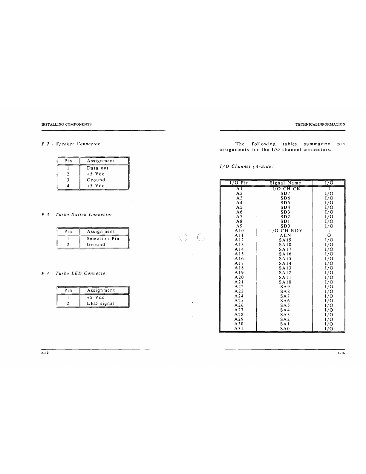
P 2 -
Speaker
Connector
The
following
tables
summarize
pin
assignments
for
the
I/O
channel
connectors.
I
Pin
I
Assignment
I
Data
out
I/O
Channel
(A-Side)
2
+5
Vdc
3
Ground
4
+5
Vdc
I
I/O
Pin
I
Signal
Name
I
I/O
I
Al
-I/O
CH
CK
I
A2
SD7
I/O
A3
SD6
I/O
A4
SD5
I/O
A5
SD4
I/O
A6
SD3
I/O
A7
SD2
I/O
P 3 -
Turbo
Switch
Connector
A8
SDI
I/O
A9
SDO
I/O
I
Pin
I
Assignment
I
Selection
Pin
A 10
-I/O
CH
RDY
I
A
II
AEN
0
A 12
SAI9
I/O
2
Ground
Al3
SA
18
I/O
A 14
SAI7
I/O
A 15
SA
16
I/O
AI6
SA
15
I/O
AI7
SAI4
I/O
A 18
SA
13
I/O
P 4 -
Turbo
LED
Connector
A 19
SA
12
I/O
A20
SA
II
I/O
A21
SAIO
I/O
A22
SA9
I/O
A23
SA8
I/O
I
Pin
I
Assignment
A24
SA7
I/O
A25
SA6
I/O
A26
SA5
I/O
I
+5
Vdc
2
LED
signal
A27
SA4
I/O
A28
SA3
I/O
A29
SA2
I/O
A30
SAl
I/O
A31
SAO
I/O
3-12
4-15

INSTALLING
COMPONENTS
'CMOS
Setup'
Reset
Jumper
Sometimes,
improper
setup
ma y cause
the
system
to
malfunction
and
you
might
not
be
able
to
correct
such
problem
without
clearing
the
entire
CMOS
Setup.
The
purpose
of
this
jumper
is
for
the
user
to
reset
the
CMOS
Setup
in
case
of
critical
error
occurred
in
the
Setup.
Make
sure
that
the
power
is
OFF
before
you
do
this
opera
tion.
Also
be
certain
tha t this
jumper
is
re-
installed
to
its
normal
position
after
resetting
the
CMOS
Setup.
After
the
CMOS
Setu,p
is
cleared,
the
Setup
will
be
loaded
with
the
BIOS
default
value
upon
power-up
and
you
may
continue
to
define
the
system
configuration
as
usual.
I
JP2 I Function
1-2
Normal
opertaion
*
2-3
Reset
CMOS
Setup
*
Default
setting
8-10
o
TECHNICALINFORMA
TION
I/O
Channel
(C-Side)
I/O
Pin
Signal
Name
I/O
CI
SBHE
I/O
C2
LA23
I/O
C3
LA22
I/O
C4
LA21
I/O
C5
LA20
I/O
C6
LA19
I/O
C7
LAI8
I/O
C8
LA17
I/O
C9
-MEMR
I/O
CIO
-MEMW
I/O
C
II
S08
I/O
CI2
S09
I/O
Cl3
SOU)
I/O
Cl4
SOli
1/0
C 15
S012
I/O
CI6
SOl3
I/O
C17
SOl4
I/O
CI8
SOl5
I/O
4-17

INSTALLING
COMPONENTS
CONTROL
OF
SYSTEM
SPEED
System
speed
can
be
selected
by
hardware
switch
and
keyboard.
Connector
P3
should
be
connected
to
the
turbo
switch
of
the
case
panel,
this
toggles
the
operation
mode
between
turbo
and
normal
mode
when
pressed.
In
addition
to
the
front-panel
switch,
you
can
also
change
the
system
speed
via
keyboard.
Press
'Ctrl',
'AIt'
and
'+'
for
turbo
mode
and
'Ctrl',
'AIt'
and
'-'
for
normal
mode.
In
either
case,
the
turbo
LED
will
light
up
to
indicate
whether
the
system
is
now
running
in
turbo
mode
or
normal
mode.
In
turbo
mode,
thc
turbo
LED
will
turned
on.
In
normal
mode,
the
turbo
LED
is
off.
It
should
be
note
that
turbo
switch
setting
will
override
the
keyboard
switching
mode,
but
not
vice
versa.
3-8
(
,-_./
Appendix
A
AMI
System
BIOS
The
system
BIOS
of
Panther-II
provides
an
interface
for
operating
systems
and
applications
to
access
the
hardware.
It
is
fully
compatible
with
s.tandard
AT
BIOS
and
works
flawlessly
in
the
network
system.
It
also
performs
self-test
after
reset
and
includes a setup
program
to
configure
the
system.
SELF-TEST
To
ensure
that
the
computer
hardware
is
functional,
the
system
BIOS
will
carry
out a self-
test
upon
reset.
The
test
is
very
intensive
and
covers
all
parts
of
hardware.
It
takes a while
before
messages
are
shown
on
the
screen.
It
does
not
mean
that
the
system
is
not
working
when
the
screen
is
blank.
So
wait
for a while
after
turning
on
the
power
and
listen
carefully
to
the
speaker.
Some
errors
are
reported
by a number
of
beep
sounds.
After
completing
the
self-test,
the
BIOS
will
display
some
messages
on
the
screen.
In
case
of
serious
er
rors,
the
BIOS
will
suspend
the
test.
If
the
display
is
not
initialized,
the
BIOS
will
report
the
error
through a sequence
of
beep
sounds.
Otherwise,
error
message
will
be
shown
on
the
screen.
A-I
INSTALLING
COMPONENTS
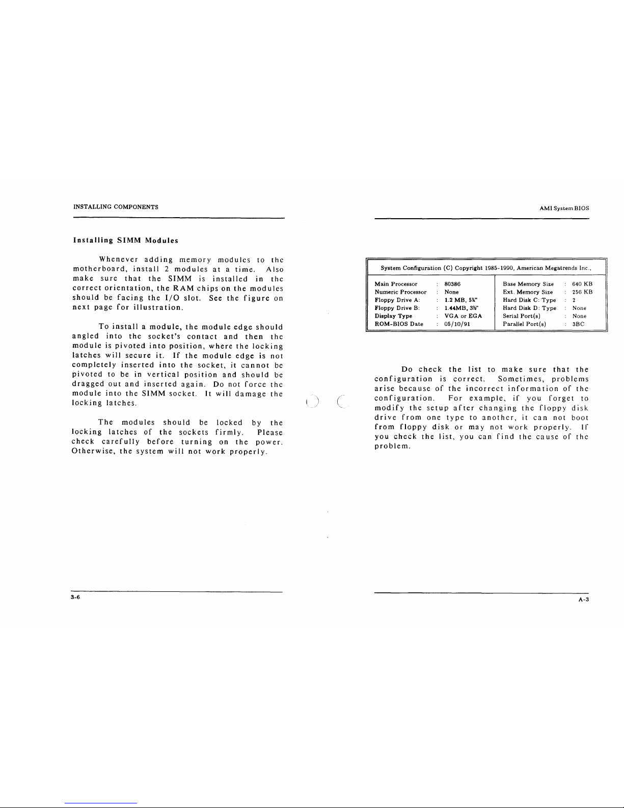
Installing
SIMM
Modules
Whenever
adding
memory
modules
to
thc
motherboard,
install 2 modules
at a time.
Also
make
sure
that
the
SIMM
is
installed
in
the
correct
orien
ta
tion,
the
RAM
chips
on
the
mod u les
should
be
facing
the
I/O
slot.
See
the
figure
on
next
page
for
illustration.
To
install a module,
the
module
edge
should
angled
into
the
socket's
contact
and
then
thc
module
is
pivoted
into
position,
where
the
locking
latches
will
secure
it.
If
the
module
edge
is
not
completely
inserted
into
the
socket,
it
cannot
bc
pivoted
to
be
in
vertical
position
and
should
be
dragged
out
and
inserted
again.
Do
not
force
the
module
into
the
SIMM
socket.
It
will
damage
the
locking
la
tches.
The
modules
should
be
locked
by
the
locking
latches
of
the
sockets
firmly.
Please
check
carefully
before
turning
on
the
power.
Otherwise,
the
system
will
not
work
properly.
3-6
I.
)
AMI
System
BIOS
System
Configuration
(C)
Copyright
1985-1990,
American
Megatrends
Inc.,
Main
Processor
:
80386
Base
Memory
Size : 640 KB
Numeric
Processor : None
Ext.
Memory
Size
: 256
KB
Floppy
Drive
A: : 1.2
MB,
5V."
Hard
Disk
C:
Type
2
Floppy
Drive
B: :
1.44MB,
3';'''
Hard
Disk
D:
Type
:
None
Display
Type
:
VGA
or
EGA
Serial
Port{s)
: None
ROM-BIOS
Date
:
05/10/91
Parallel
Portis)
3BC
Do
check
the
list
to
make
sure
that
the
conf
igura
tion
is
correct.
Sometimes,
pro
ble
ms
arise
because
of
the
incorrect
information
of
the
configuration.
For
example,
if
you
forget
to
modify
the
setup
after
changing
the
floppy
disk
drive
from
one
type
to
anothcr,
it
can
not
boot
from
floppy
disk
or
may
not
work
properly.
If
you
check
the
list,
you
can
find
the
ca
use
of
thc
problem.
A-3
 Loading...