

Page 1

FD1803-E Powerline Ethernet Bridge
FD1803-U Powerline USB Adapter
User’s Manual
Page 2

Contents
1. Introduction 3
1.1 Overview 3
1.2 Features & Specifications 4
1.2.1 Features 4
1.2.2 Specifications
5
1.3 Package Contents 6
2. Installing FD1803-E Procedures 7
2.1 FD1803-E Product Outlook 7
2.2 FD1803-E LED Display 8
2.3 Hardware Installation 9
2.4 Setting the IP Address 11
2.5 Installing Utilities and Connecting FD1803-E 13
3. Installing FD1803-U Procedures 18
3.1 FD1803-U Product Outlook 18
3.2 FD1803-U LED Display 19
3.3 Installing Utilities and Connecting FD1803-U 20
3.4 Connecting FD1803-U 25
3.5 Setting the IP Address 26
4. Running the Utility 28
4.1 Device Connecting Status 28
4.2 Scanning Powerline Network 30
4.3 Setting Network Password 31
4.4 Advanced Setting 32
Appendix A: Testing the setup 33
Appendix B: Application Diagram 34
2
Page 3

1.FD1803-E & FD1803-U Introduction
1.1 Overview
The FD1803-E Ethernet Bridge and the FD1803-U USB Adapter
which use existing powerline to access network is the best solution for
home and SOHO to build up a network. FD1803-E/U transmits the
data on electrical wiring. It does not require any new wires and it is
both robust and affordable. It solves key issues that have plugged
home networking in the past.
FD1803-E/U supporting standard outlet lets it more convenient to
move the PCs, and printer servers. Because power outlets are located
on nearly every wall of a house, with FD1803-E/U, the users can
connect the network or share dial-up, DSL and cable Internet access.
FD1803-E/U can co-exiting with phoneline and RF networks with
no known problems. FD1803-E/U can eliminate some of the problems
with networking, allowing access points to be moved to more
convenient locations in the home, reducing the need for multiple
wireless access points.
FD1803-E/U provides 56-bit DES security technology to ensure
network separation between homes. FD1803-E/U uses encryption to
block outside access. The technology is a federal standard that
provides a level of security that is adequate for home networking.
FD1803-E/U supports maximum 14Mbps bandwidth over home AC
wiring. It offers you a high-speed networking for information sharing,
multimedia application and gaming. FD1803-E/U provides a complete
powerline connectivity solution.
3
Page 4

1.2 Features & Specifications
1.2.1 Features
• Use existing powerline networks--no extra wiring and extra wire
maintenance
• Use standard outlet/plug. Access the network everywhere at home
• With an USB type B connector, connect to PCs USB port directly
• Use power outlet to let the users more easily relocate the PCs,
printers
• Easy to connect with another powerline Bridge to access Internet
or existing home network
• 56-bit DES encryption provide you high security
• Immediate LED indicators for easy troubleshoot.
• Co-exist with current technology to protect previous investment
• Maximum 14Mbps bandwidth over standard home powerlines for
sharing information, multimedia application and gaming
• Frequency band 4.3 to 20.9MHz for low inference from other
electric appliances
4
Page 5

1.2.2 Specifications
FD1803-E FD1803-U
Standard IEEE 802.3/IEEE 802.3u USB 1.1
Ports
Powerline
Network
Cabling Type
Powerline
Network
Speed
Powerline
Network
Encryption 56-bit DES Encryption 56-bit DES Encryption
Installation Plug-and-Play Plug-and-Play
Power Supply Internal Power Adapter USB Port
Certification FCC Class B, CE FCC Class B, CE
Dimensions 70.5mm X 100mm X 40.6mm 70.5mm X 100mm X 40.6mm
1* Powerline Port
1* 10/100BASE-TX RJ-45 Port
Power Cord
Cat 3,4,5,5e,6 UTP Cable
Maximum 14Mbps
10 Mbps
1* Powerline Port
1* USB Port
Power Cord
Standard USB Cable
Maximum 14Mbps
12 Mbps
Table 1-1 FD1803-E and FD1803-U specifications.
5
Page 6

1.3 Package Contents
FD1803-E:
•One Ethernet to Powerline device
•One Power Cord
•One Quick Installation Guide
•One Setup Utility CD-ROM
•Robber Foot
FD1803-U
•One USB to Powerline device
•One USB Cable
•One Power Cord
•One Quick Installation Guide
•One Setup Utility CD-ROM
•Rubber Foot
:
6
Page 7
2. Installation FD1803-E Procedures
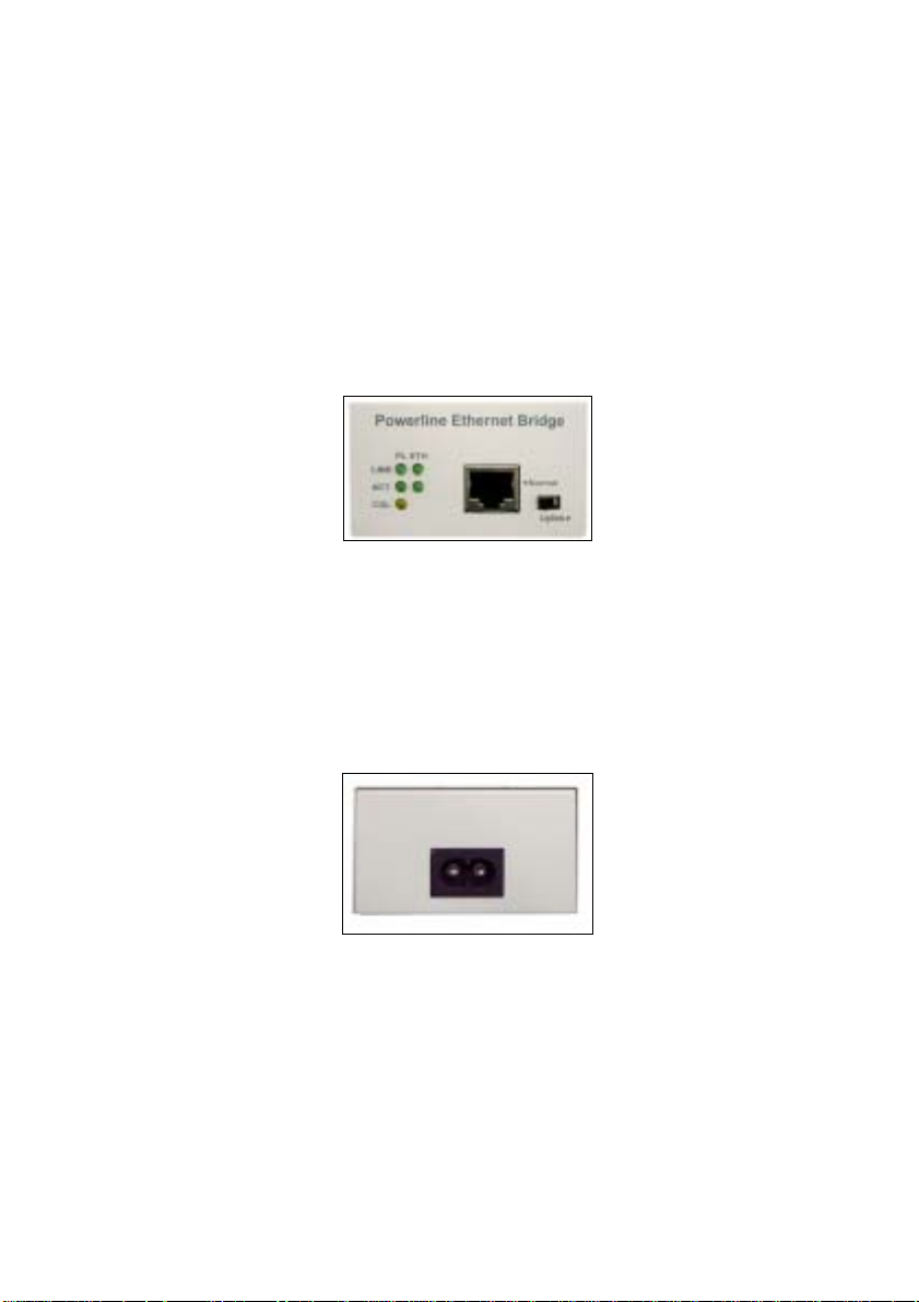
2.1 FD1803-E Product Outlook
FD1803-E Front Panel
Using the 10/100 BASE-T RJ-45 port connects to NIC or Switch/ Hub.
Figure 2-1 Front View of FD1803-E
Normal/Uplink Switch explanation:
Normal: Used to link NIC or Router.
Uplink: Used to link Switch or Hub.
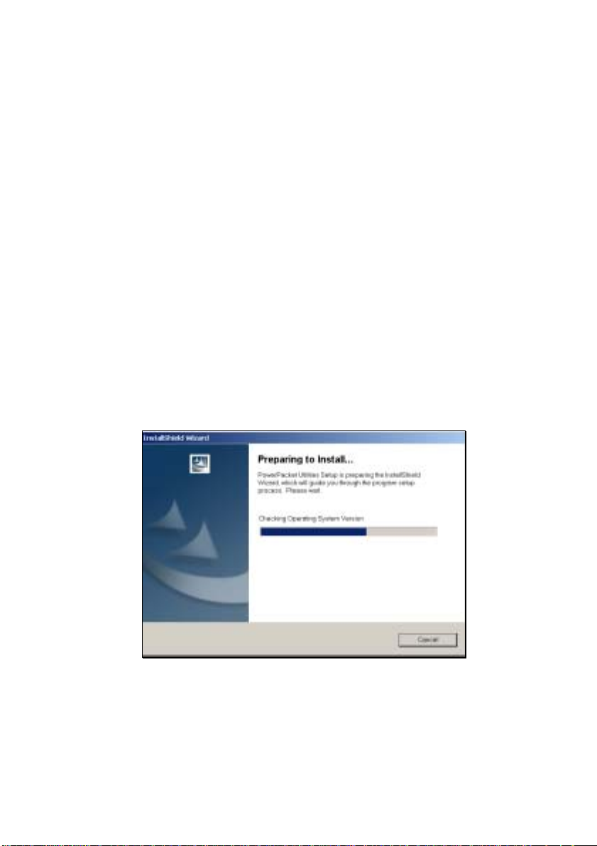
FD1803-E Rear Panel
Using the Powerline Port connects to power outlet.
Figure 2-2 Rear View of FD1803-E
7
Page 8

2.2 FD1803-E LED Display
FD1803-E LED Explanations:
LED Status Function
LINK Green Lights to indicate a functional
network link through the port with
ETH
PL
ACT Green Lights to indicate that there is LAN
LINK Green Lights to indicate that the
ACT Green Lights to indicate that there is
COL Orange Flashes to indicate there is a
Table 2-1 FD1803-E LED Explanations
an attached device.
traffic.
powerline device has plugged into
powerline and found other
powerline device(s).
powerline network traffic.
collision detected on powerline.
8
Page 9

2.3 Hardware Installation
This section introduces how to connect FD1803 correctly.
Important: Use only the supplied power cord to connect the 10/100
Bridge to the power outlet.
Important: Because the FD1803-E sends data over the powerlines,
it is recommended that you plug its power cord directly into a
power outlet. Do not plug the device into a UPS or power strip
with surge protection. The FD1803-E has its own power filter for
protection against surges.
Connect to a Hub/Switch
1. Plug straight Ethernet cable into the FD1803-E.
2. Plug the other side into the Hub or Switch’s normal port.
3. Switch to Mode Switch to “Uplink”.
4. Plug the supplied power cord into the FD1803-E and an AC
outlet.
Connect to a Router
1. Plug straight Ethernet cable into the FD1803-E.
2. Plug the other side into the Router’s LAN port.
3. Switch the Mode Switch to “Normal”.
4. Plug the supplied power cord into the FD1803-E and an AC
outlet.
Connect to a PC
1. Install an NIC into the PC.
2. Install TCP/IP protocol.
3. Setup NIC IP address.
4. Install FD1803-E Utility.
5. Plug straight Ethernet cable into the FD1803-E.
6. Plug the other side into the NIC port.
7. Switch to Mode Switch to “Normal”.
8. Plug the supplied power cord into the FD1803-E and an AC
outlet.
For more information about “Setup IP address”, please refer to 2.4
Setting the IP Address.
9
Page 10

For more information about Install FD1803-E Utility, please refer to
2.5 Installing Utilities and Connecting FD1803-E.
10
Page 11

2.4 Setting the IP Address
If you didn’t use DHCP service, you may need to check the NIC’s IP
address to ensure that your powerline network is fully functional before
starting installation. If you are sure no IP setting problems on your
computer, proceed to 2.5 Installing Utilities and Connecting FD1803.
Windows defaults to setting up your network device to automatically
select an IP address. If you want to assign an IP address in your
computer, follow below steps to set the IP addresses correctly.
Setting the IP Address in Windows 2000
1. Open ‘Control Panel’ – ‘Network and Dial up connections’.
2. Right click on the Local Area Connection and select ‘Properties’.
3. Verify the Internet Protocol (TCP/IP) is present. If it isn’t present:
• Click ‘Install’.
• Select ‘Protocol’ and click Add.
• Select Internet Protocol (TCP/IP) and click OK.
4. On the ‘General tab’, select Internet Protocol (TCP/IP) and click
‘Properties’.
5. Select ‘Use the following IP address’.
6. Enter an IP address on the same subnet as the other powerline
devices.
7. Enter a proper Subnet mask.
8. Enter the correct DNS server address.
9. Click OK.
10. Click OK to exit the ‘Properties’ window.
Setting the IP Address in Windows XP
1. Open ‘Network Connections’.
2. Right click on the Local Area Connection and select ‘Properties’.
3. Verify the Internet Protocol (TCP/IP) is present. If it isn’t present:
• Click ‘Install’.
• Select ‘Protocol’ and click Add.
• Select Internet Protocol (TCP/IP) and click OK.
4. On the ‘Networking tab’, select Internet Protocol (TCP/IP) and
click ‘Properties’.
5. Select ‘Use the following IP address”.
6. Enter an IP address on the same subnet as the other powerline
devices.
7. Enter a proper subnet mask.
11
Page 12

8. Enter the correct DNS server address.
9. Click OK.
10. Click OK to exit the ‘Properties’ window.
Setting the IP Address in Windows 98
1.Open ‘Control Panel’ – ‘Network’.
2.Verify the TCP/IP Protocol is present. If it isn't:
• Click Add.
• Double-Click Protocol.
• Scroll down the list and select Microsoft.
• Choose TCP/IP and click OK.
You may be prompted for your Windows98™ CD-ROM. Cli ck OK.
3. Select the TCP/IP from the list of installed network components.
Click on Properties. Select ‘IP Address tab’. Enter an IP address
on the same subnet as the other powerline devices.
4. Enter a proper subnet mask.
5. Select ‘DNS Configuration tab’ and enter the correct DNS
address.
6. Select ‘Gateway tab’ and enter a default gateway address in your
network.
7 Select ‘WINS Configuration tab’ and disable WINS Resolution.
8. Click OK.
9. Click OK to exit the ‘Properties’ window.
12
Page 13
2.5 Installing Utilities and Connecting FD1803-E
PowerPacket Configuration Utility only supports for Windows
98SE, ME, 2000, or XP. This section gives an example of installing
process in Windows 2000. Windows 98SE, ME and XP users please
also refer to it.
Important: Use only the supplied power cord to connect the
10/100 Bridge to the power outlet.
Important: Because the FD1803-E sends data over the
powerlines, it is recommended that you plug its power cord
directly into a power outlet. Do not plug the device into a UPS
or power strip with surge protection. The FD1803-E has its own
power filter for protection against surges.
Windows 2000
2. Insert the Setup utility CD-ROM into the computer’s CD-ROM
drive. Click the Start button and choose Run. In the box that
appears, enter D:\FD1803-E\setup.exe (Where D is the letter of
your CD-ROM drive).
Figure 2-3 Preparing to Install Screen
2. The CD will launch an installation utility similar to that shown in
Figure 2-4. Click the Next button to continue.
13
Page 14

Figure 2-4 Welcome Screen
3.Accept terms and click Next to continue.
Figure 2-5 Restricted Software License Agreement Screen
4.Enter User Name and Organization. User Name and
Organization have on importance in installation process and
device operation. Click Next to Continue.
14
Page 15

Figure 2-6 Customer Information Screen
5. Click the Finish button to exit the installation u tility.
Figure 2-7 Confirm Screen
Windows 2000 users: Windows will inform you
that there was no digital signature found. Click
the Yes button to proceed with the installation.
15
Page 16

Windows XP users: Windows will notify you
that the software has not passed Windows Logo
testing. Click the Continue Anyway button.
6. When prompted by the Install Utility, Plug in the FD1803-E. To
plug in the FD1803-E, you need to:
• Plug the supplied power cord into the FD1803-E and an AC
outlet.
• Plug any Ethernet cable into the FD1803-E and an available
Ethernet port on your PC.
For more information, refer to 2.6 Connecting FD1803-E.
Figure 2-8 Inform to Connect FD1803-E Screen
7. Click the Finish button to exit the installation u tility.
16
Page 17

Figure 2-9 Installation Completed Screen
8. You may be asked to restart your computer. Click the Yes button
to restart now, or click the No button to restart later.
Figure 2-10 Confirm to Reboot Screen
9. The installation of the PowerPacket Configuratio n Utilities is
complete.
17
Page 18

3. Installation FD1803-U Procedures
3.1 FD1803-U Product Outlook
FD1803-U Front Panel
Using the USB port connects to PC’s USB port.
Figure 3-1 Front View of FD1803-U
FD1803-U Rear Panel
Using the Powerline Port connects to power outlet.
Figure 3-2 Rear View of FD1803-U
18
Page 19

3.2 FD1803-U LED Display
FD1803-U LED Explanation:
LED Status Function
USB Green Lights to indicate the powerline device has
plugged into a USB port.
LINK Green Lights to indicate that the powerline device
has plugged into powerline and found other
powerline device(s).
ACT Green Lights to indicate there is powerline
network traffic.
COL Orange Flashes to indicate there is a collision.
Table 3-1 FD1803-U LED Explanations
19
Page 20

3.3 Installing Utilities and Connecting FD1803-U
PowerPacket Configuration Utility only supports for Windows
98SE, ME, 2000, or XP. This section gives an example of installing
process in Windows 2000. Windows 98SE, ME and XP users please
also refer to it. Please follow the procedures below to install FD1803U.
Windows 2000
1. Insert the Setup utility CD-ROM into the computer’s CD-ROM
drive. Click the Start button and choose Run. In the box that
appears, enter D:\FD1803-U\setup.exe (Where D is the letter of
your CD-ROM drive).
Figure 3-3 Preparing to Install Screen
2. The CD will launch an installation utility similar to that shown in
Figure 3-4. Click the Next button to continue.
20
Page 21

Figure 3-4 Welcome Screen
3. Accept terms and click Next to continue.
Figure 3-5 Restricted Software License Agreement Screen
4. Enter User Name and Organization. User Name and
Organization have on importance in installation process and
device operation. Click Next to Continue.
21
Page 22

Figure 3-6 Customer Information Screen
5. Click Install to begin installation of the Security Configuration
Utility.
Figure 3-7 Confirm Screen
Windows 2000 users: Windows will inform you
that there was no digital signature found. Click
the Yes button to proceed with the installation.
22
Page 23

Windows XP users: Windows will notify you
that the software has not passed Windows Logo
testing. Click the Continue Anyway button.
6. When prompted by the Install Utility, plug in the FD1803-U.
To plug in the FD1803-U, you need to:
• Plug the supplied power cord into FD1803-U and an AC outlet.
• Plug the supplied USB cable into the FD1803-U and an
available USB port on your PC.
For more information, refer to 3.4 Connecting FD1803-U.
Figure 3-8 Inform to Connect FD1803-U Screen
If this is the first time the USB adapter has been installed,
the Windows Found New Hardware Wizard may launch. If
the wizard does not automatically find the drivers, you need to
browse to the following location C:\Program
Files\PowerPacket\USB Drivers or the folder where the
utility is stored to find the driver.
Important: Use only the supplied power cord to connect the
USB Adapter to the power outlet.
Important: Because the FD1803-U sends data over the
powerlines, it is recommended that you plug its power cord
directly into a power outlet. Do not plug the device into a
23
Page 24

UPS or power strip with surge protection. The FD1803-U
has its own power filter for protection against surges.
7. Click the Finish button to exit the installation u tility.
Figure 3-9 Installation Completed Screen
8. You may be asked to restart your computer. Click the Yes button
to restart now, or click the No button to restart later.
Figure 3-10 Confirm to Reboot Screen
9. The installation of the PowerPacket Configuratio n Utilities is
complete.
24
Page 25

3.4 Connecting FD1803-U
This section introduced how to connect FD1803-U properly. If you
are sure no connections problems on FD1803-U, proceed to 3.5 Setting
the IP Address.
1. Insert the standard USB cable with the Type A connector into the
computer’s USB port.
2. Insert the other end of USB cable with Type B connector into the
USB port on the USB Adapter.
3
. Plug the power cord into the powerline port on the FD1803-U.
4. Plug the other end of the power cord into a power outlet.
USB Type A
Connector
USB Type B
Connector
Important: Use only the supplied power cord to connect the
USB Adapter to the power outlet.
Important: Because the FD1803-U sends data over the
powerlines, it is recommended that you plug its power cord
directly into a power outlet. Do not plug the device into a
UPS or power strip with surge protection. The FD1803-U
has its own power filter for protection against surges.
25
Page 26

3.5 Setting the IP Address
After completing the installation successfully, you may need to set
the IP address to ensure that your powerline network is fu lly
functional if you didn’t use DHCP service. If you are sure no IP
setting problems on your computer, proceed to 4. Running the Utility.
Windows defaults to setting up your network device to
automatically select an IP address. If you want to assign an IP address
in your computer, follow below steps to set the IP address correctly.
Setting the IP Address in Windows 2000
1. Open ‘Control Panel’ – ‘Network and Dial up connections’.
2. Right click on the Local Area Connection corresponding to the
USB PowerPacket Network Adapter and select ‘Properties’.
3. Verify the Internet Protocol (TCP/IP) is present. If it isn’t present:
• Click ‘Install’.
• Select ‘Protocol’ and click Add.
• Select Internet Protocol (TCP/IP) and click OK.
4. On the ‘General tab’, select Internet Protocol (TCP/IP) and click
‘Properties’.
5. Select ‘Use the following IP address’.
6. Enter an IP address on the same subnet as the other powerline
devices.
7. Enter a proper Subnet mask.
8. Enter the correct DNS server address.
9. Click OK .
10. Click OK to exit the ‘Properties’ window.
Setting the IP Address in Windows XP
1. Open ‘Network Connections’.
2. Right click on the Local Area Connection corresponding to the
USB PowerPacket Network Adapter and select ‘Properties’.
3. Verify the Internet Protocol (TCP/IP) is present. If it isn’t present:
• Click ‘Install’.
• Select ‘Protocol’ and click Add.
• Select Internet Protocol (TCP/IP) and click OK.
4. On the ‘Networking tab’, select Internet Protocol (TCP/IP) and
click ‘Properties’.
5. Select ‘Use the following IP address”.
26
Page 27

6. Enter an IP address on the same subnet as the other powerline
devices.
7. Enter a proper subnet mask.
8. Enter the correct DNS server address.
9. Click OK.
10. Click OK to exit the ‘Properties’ window.
Setting the IP Address in Windows 98
1.Open ‘Control Panel’ – ‘Network’
2.Verify the TCP/IP Protocol (or TCP/IP -> USB PowerPacket
Network Adapter) is present. If it isn't:
• Click Add.
• Double-Click Protocol.
• Scroll down the list and select Microsoft.
• Choose TCP/IP and click OK.
You may be prompted for your Windows98™ CD-ROM. Cli ck OK.
3. Select the TCP/IP from the list of installed network components.
Click ‘Properties’.
4. Select ‘IP Address tab’. Enter an IP address on the same subnet as
the other powerline devices.
5. Enter a proper subnet mask.
6. Select ‘DNS Configuration tab’ and enter the correct DNS
address.
7. Select ‘Gateway tab’ and enter a default gateway address in your
network.
8. Select ‘WINS Configuration tab’ and disable WINS Resolution.
9. Click OK.
10. Click OK to exit the ‘Properties’ window.
27
Page 28

4. Running the Utility
To run the utility, double click the Configuration Utility icon on your
desktop.
Note: Make sure your TCP/IP protocol is set up appropriately on
your computer before running the Utility. And also your IP address,
for more information refers to 2.4 Setting the IP Address or 3.5
Setting the IP Addressing.
4.1 Device Connecting Status
The Device dialog screen provides a list of your powerline devices
connected to the computer, where the utility is running and initially it
shows the average data rate performance of your powerline network.
Figure 4-1 Device Dialog Screen
Click on one of them and hit Connect. The progress bar will change
into a status bar indicating the network average data rate. The color of
the bar reflects the average performance of the powerline network:
Green
: Good performance
28
Page 29

Yellow: Average performance
Red: Poor performance
29
Page 30
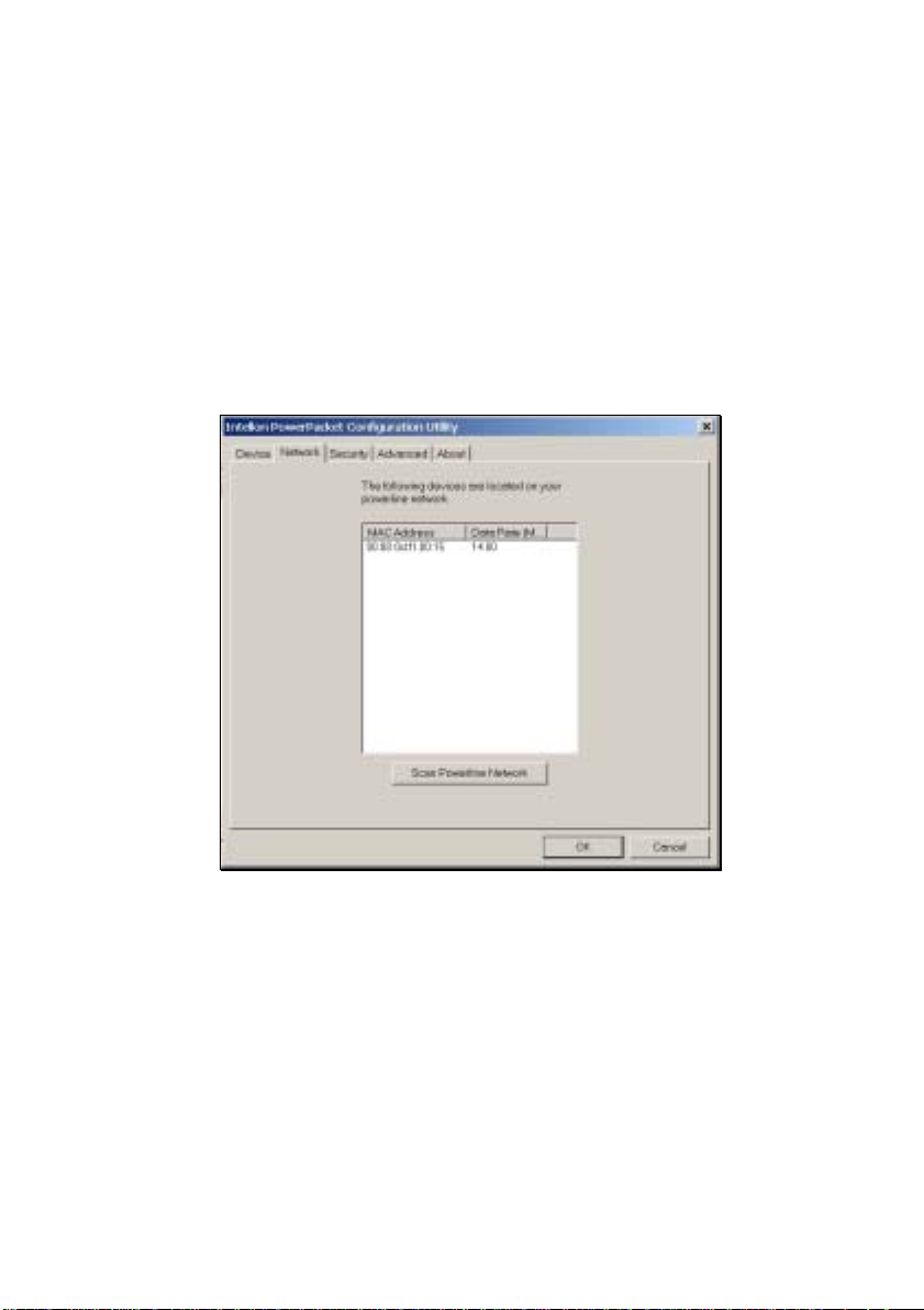
4.2 Scanning Powerline Network
The Network dialog screen provides detailed information about
your powerline network.
The text list box shows all powerline devices found on your
powerline network identified by their MAC addresses. A second
column indicates their data rate measurements in Mbps.
Press Scan Powerline Network button to refresh the listed
information.
Figure 4-2 Network Dialog Screen
30
Page 31
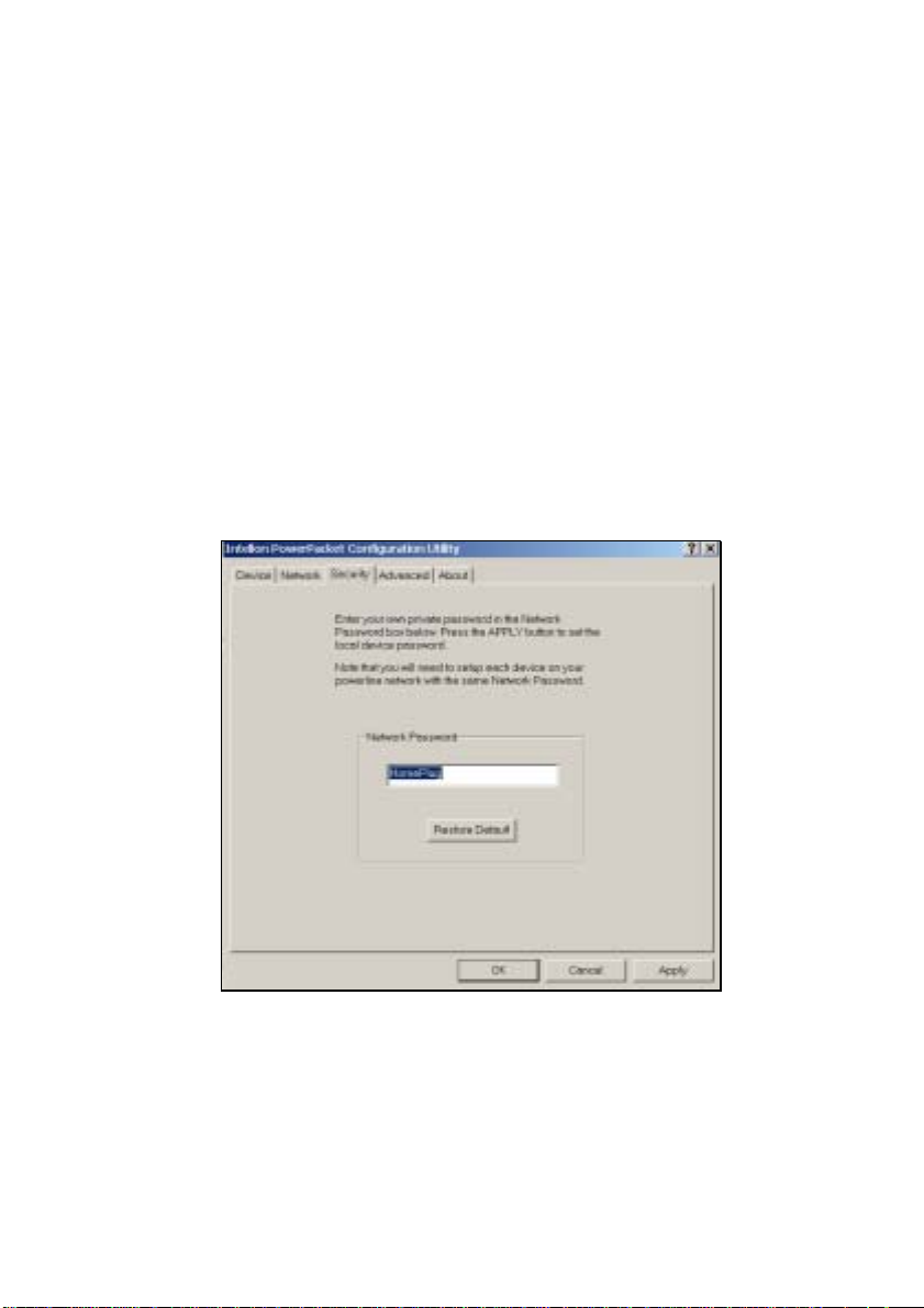
4.3 Setting Network Password
After installing your FD1803-E Ethernet Bridge or FD1803-U USB
Adapter and USB driver, you will run the Security Configuration
Utility for each Powerline device. This utility will set up security
using a network password.
FD1803-E/U all use “HomePlug” as a default network password.
The Security dialog screen allows you to change this network
password and set your own private password and apply it to the
powerline device connected to the computer where the utility is
running.
Hit Restore Default button to restore the original network
password “HomePlug”.
Hit Apply or OK buttons to set the password into your local device.
Figure 4-3 Security Dialog Screen
Important: Your private network password must have between 4
and 24 characters. The password is case sensitive. The password
can include any letters of the alphabet, numbers or punctuation
marks. Remember this password, as it will be needed when
adding other devices to the network later.
31
Page 32

4.4 Advanced Setting
The Advanced dialog screen allows you to set up a network
password remotely on other powerline devices through the powerline.
Type your private network password into the Network Password
text box.
The other devices on the network with powerline capab ilities will
have a different password--DEK printed on either the box itself or in
the documentation. Find the passwords for all devices you want to
manage and type them one by one into the Add Password text box
and hit Add. This will add the passwords to Remote Passwords text
list box.
Hit Set All to apply your private network password to all devices
that are listed in the Remote Passwords text list box and to your local
device connected to the computer where the utility is running as well.
Select a password and Hit Remove to remove it from the list.
Figure 4-4 Advanced Dialog Screen
32
Page 33

Appendix A: Testing the Setup
To verify the PowerPacket network is working correctly, use the
standard “Ping” utility.
1. Ping the IP address of the PowerPacket node using the same
computer that the node is connected to. If this fails, there is a
problem with the network interface.
2. Repeat the same process with the other PowerPacket nodes on
the network.
3. If all nodes can ping themselves, try pinging another powerline
node on the network. If this fails, verify that your IP addresses are
on the same subnet. If this is correct, then make sure that the
advanced setup and encryption keys are set properly. If this is
correct, then most likely, there is a problem with connections on the
powerline. Try a different AC outlet.
33
Page 34

Appendix B: Application Diagram
Application 1: Implement powerline network between different rooms.
Connect your PCs and printers and share Internet
access.
Figure C-1
Application 2: Implement powerline network between 2 small LAN.
34
Page 35

Figure C-2
Application 3: Implement powerline network between WLAN and
LAN.
Figure C-3
35
Page 36

For more information please contact
TEL:886-2-2218-3330
FAX:886-2-2218-3340
http://www.svec.com
E-mail:support@svec.com.tw
36
 Loading...