

Page 1

1
Installation Guide
Model: HD4XSTPMX
PRO HD HOME THEATER SERIES
Page 2

2
Contents
Application Diagram ........................................................ 3
Features .......................................................................... 3
Matrix Front Panel Overview ................................................ 4
Basic Front Panel Control ............................................... 5
Matrix Back Panel Overview ........................................... 6
Zone Receiver (RX) Overview ........................................ 7
Infrared Overview ........................................................... 8
Remote Control Guide .................................................... 9
Ethernet cable recommendations ................................. 10
Ethernet cable installation recommendations ............... 10
Installation:Basic Installation ......................................... 11
IR Installation ................................................................ 13
EDID Configuration ....................................................... 14
Changing EDID mode .......................................................... 15
Scene Select……...........................................................16
Scene Programming ..................................................... 17
USB Service Port…….....................................................18
Serial Control………………….........................................19
Serial Control RS-232 Control Setup…..........................20
Serial Control Via LAN Port Control Setup.....................21
Serial Commands- (Basic)..............................................26
Serial Commands- (switching)........................................27
Serial Commands- (Forwarding)……………...................29
Zone Receiver Serial Data (RS-232) Port…...................30
RS-232 / Phoenix Cabling……………….….....................30
Installing Transmitter Output cards…………...................31
Specifications…………....................................................33
Warranty..........................................................................34
Disclaimers......................................................................34
Page 3
3
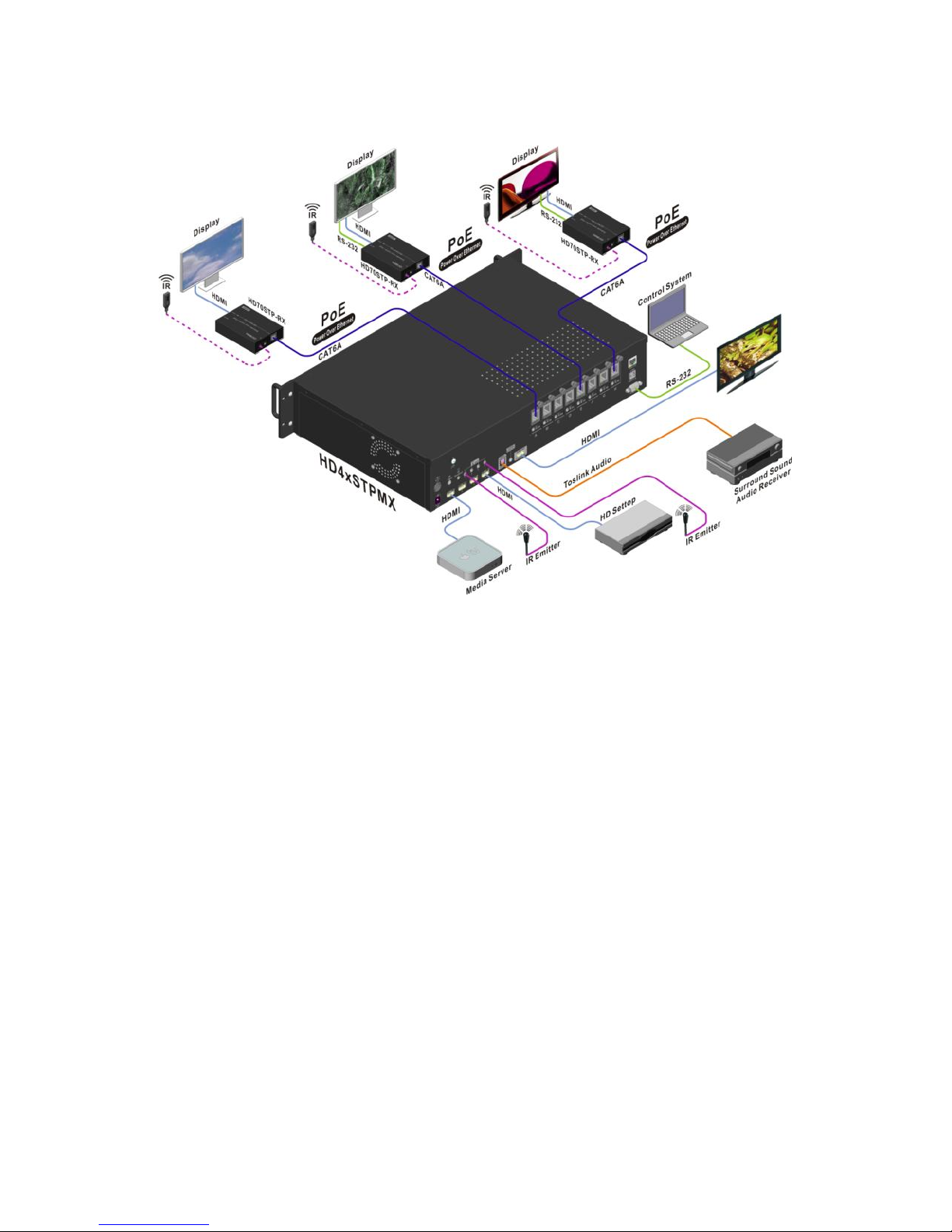
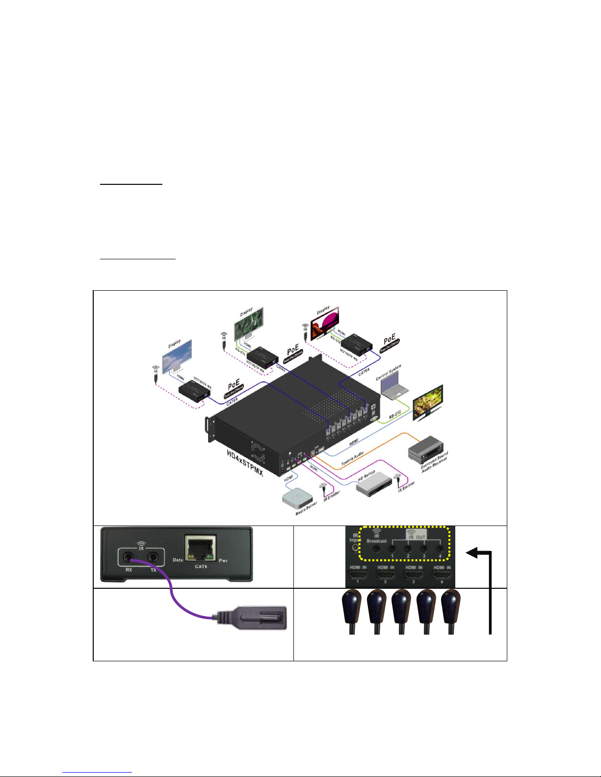
Application Diagram
Features:
4 inputs, up to 8 outputs (Installer configurable).
Non-blocking Matrix – view Any Source on Any Display.
3D, 1080P, and 4K resolutions supported.
Distributes HD video + Audio over single CAT6 cables up to 200ft
(60m).
Power over Ethernet provides power to Zone Receivers.
IR and RS-232 over the same CAT6 cable.
IR from remote Zones to control the Matrix, 4x Sources (Routed)
and your AVR.
RS-232 command forwarding to each Zone over CAT6.
EDID Management plus custom EDID via USB service port.
Front panel control for Scene setting/selection (with full lock out).
Discrete IR codes for simple system integration.
Wired IR port for In-cabinet installations.
Page 4
4
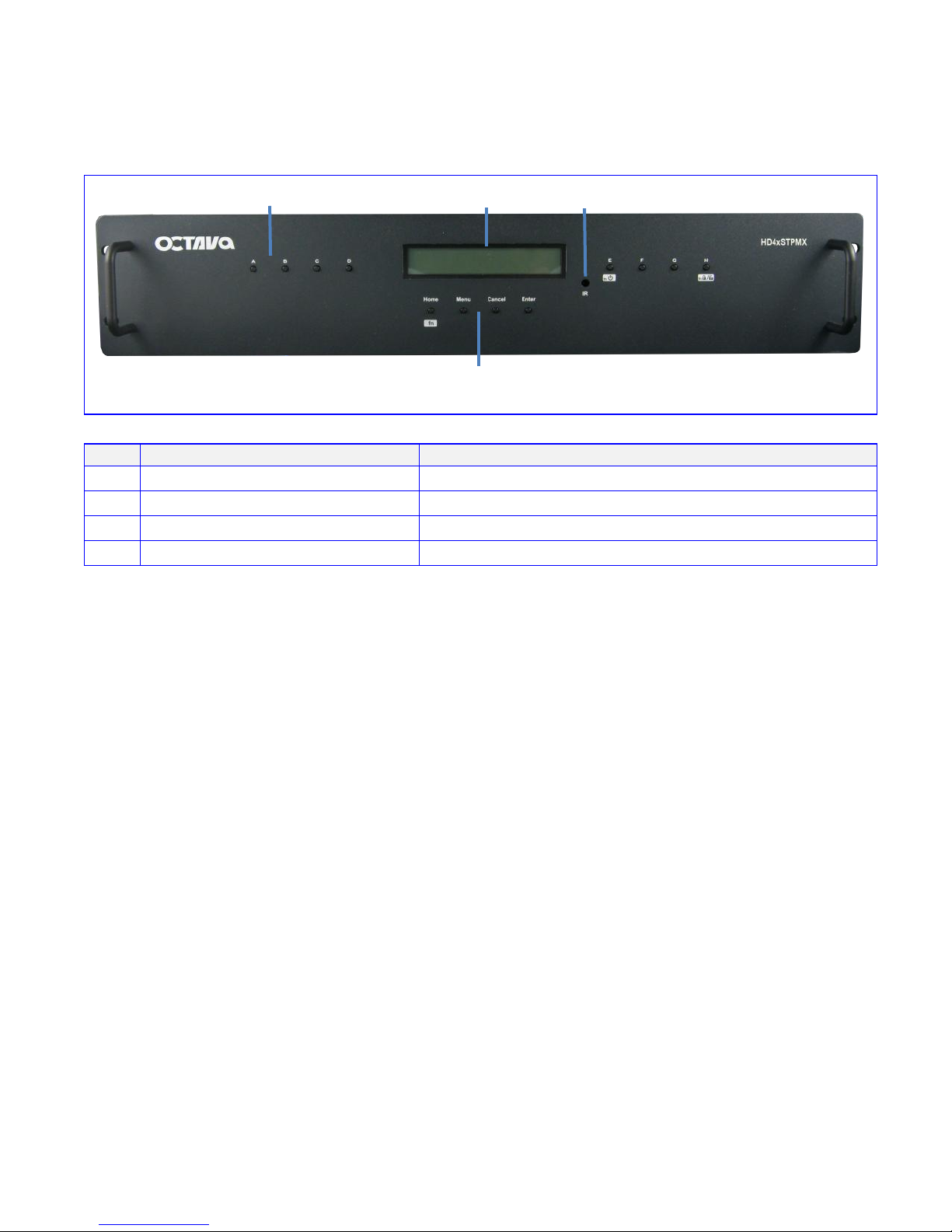
Matrix Front Panel Overview:
Item
Description
1
Output Select
Press to switch inputs for output Zones
2
LED Display
3 IR Receiver
IR receiver
4
Control and function select
1-Output Select
2-Led Display
3- IR Receiver
4- Control and function select
Page 5
5
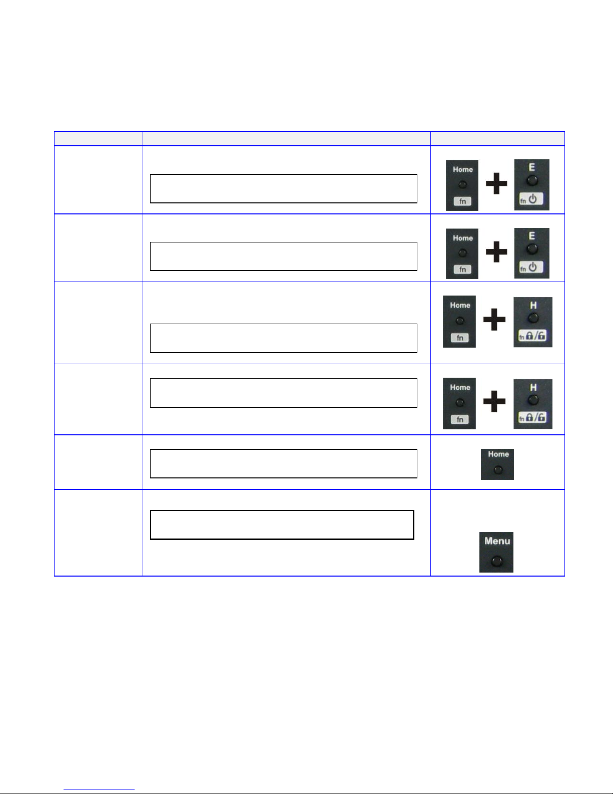
Basic Front Panel Control:
Description
LCD Display
Turn On
matrix
Turns On the matrix from the front panel
P o w e r O N
Press fn+ power on/off
Turn On/OFF
matrix
Turns Off the matrix from the front panel
P o w e r O F F
Press fn+ power on/off
Lock front
panel
buttons.
Lock the front panel buttons to prevent accidental
switching. When front panel button locked, pressing
front panel buttons will be ignored.
O U T : A B C D E F G H
I N : 1 1 1 1 1 1 1 1 L O C
K
Press fn + lock/unlock
Unlock front
panel
buttons.
Unlocks the front panel buttons.
O U T : A B C D E F G H
I N : 1 1 1 1 1 1 1 1
Press fn + lock/unlock
Home Menu
O U T : A B C D E F G H
I N : 1 1 1 1 1 1 1 1
Press Home
Firmware
/EDID
Version
F i r m w a r e V e r - 1 . 0 E D I D A
Press Menu until
version screen
displays
Page 6
6
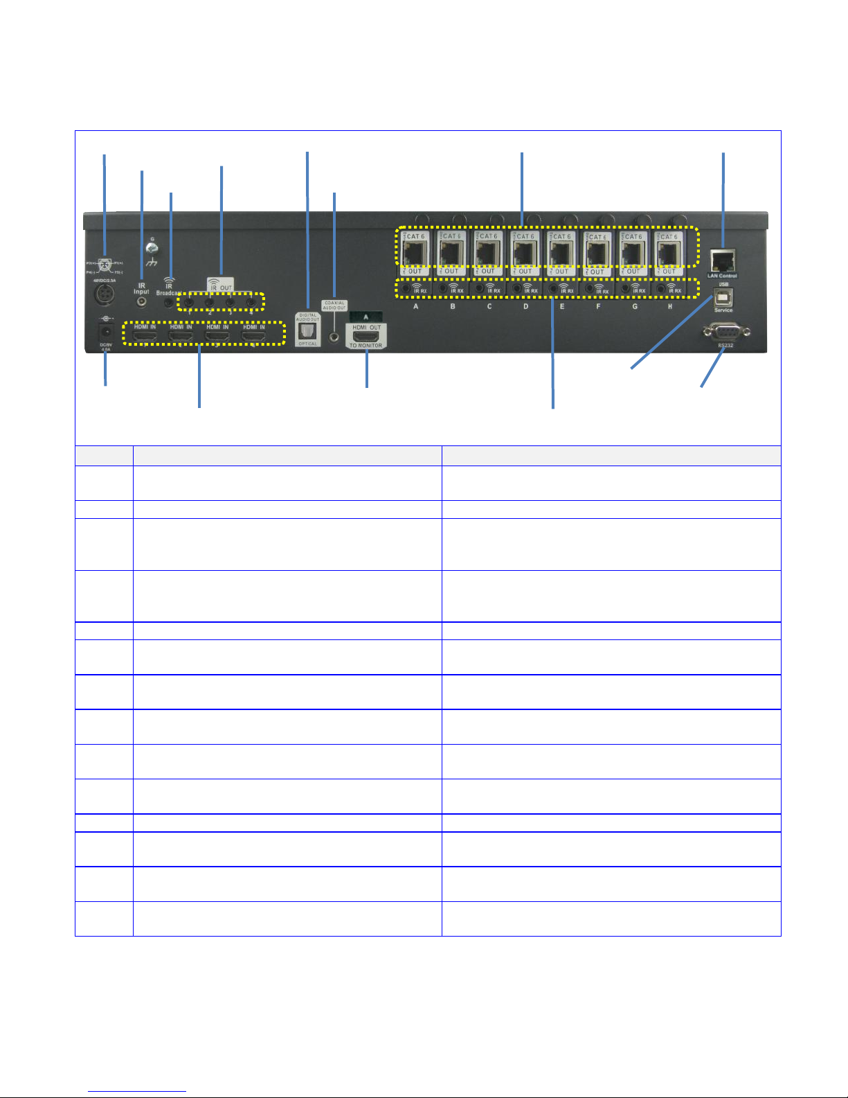
Matrix Back Panel Overview:
Item
Description
5
Power 48v (PoE)
provides power to Octava PoE compatible Zone
Receiver (Rx) units
6
Power 9v (Matrix)
provides power to Octava Matrix
7
Wired IR input
connect Octava supplied IR Receiver Extension
cable ( optional) for hidden cabinet installs
requiring line of sight for IR control.
8
IR Broadcast Port. All IR signals received
from the zone receivers can be sent out thru
the IR Broadcast port
connect Octava supplied IR emitter
cable(optional)
9
IR Output (1-4)
connect Octava supplied IR emitter cable
10
HDMI Input (1-4)
connect High Speed HDMI cables to Source
device.
11
HDMI Output (A) Note 1
connect High Speed HDMI cables to AVR or
Display device.
12
Optical Audio Output Note 1
Outputs audio over Toslink. Audio will play the
Out A source selection.
13
Analog 2ch Audio Note 1
Outputs audio over 2ch. Audio will play the Out A
source selection.
14
CAT6 Output (A-H)
connect Twisted Pair cables to Octava Zone
Receiver (Rx) unit.
15
USB Port
for custom EDID/ code updates
16
RS232 Port
for external control of Matrix via PC or 3rd party
Control system.
17
LAN Port
for external control of Matrix via PC or 3rd party
Control system.
18
IR RX inject
To send IR control to connected display using IR
port from Control System
Note 1: HDMI Output, Toslink and Analog 2ch output all "mirror" Zone A
8
14
16
5
7
12
13
17
6
10
9
15
11
18
Page 7

7
Zone Receiver (RX) Overview:
A Zone Rx unit is positioned close to your display device and connected to the Octava
Matrix with a Twisted Pair (CAT6) cable.
An Octava compatible Zone receiver must be used with the HD4xSTPMX Matrix.
Compatible Zone Receiver: HD70STP-RX
The HD70STP-RX Zone Receiver uses Power over Ethernet, PoE and is directly
powered by the HD4xSTPMX over the CAT6 cable.
Item
Description
ZR-1
CAT6 In
Connect to HD4xSTPMX with CAT6
ZR-2
HDMI Out to display
Connect to HDTV using High Speed HDMI
cable
ZR-3
Power /Data Indicator
indicates Zone Receiver is receiving power and
linked with the matrix unit.
ZR-4
IR RX (receive)
connect Octava supplied IR Receiver cable.
ZR-5
IR TX (transmit)
Optional. Connect with an Octava IR emitter, if
IR control of TV is needed. For example, your
control system controls your display using I.R.
ZR-6
RS-232
Optional. Connect with a RS-232 cable if you
need to control your display using RS-232.
ZR-3 Power / Data indicator
ZR-1 CAT6 In
ZR-6 RS-232
ZR-2 HDMI to display
ZR-4 IR RX
ZR-5 IR TX
Page 8
8
Infrared Overview:
IR can be routed from any of the 8 connected Zones back to control:
1) the Matrix and 2) the connected Source devices. The Matrix also
allows IR Routing + IR Broadcast for maximum utility.
Routed IR: The IR Out 1-4 are "routed" for optimum IR control.
For example, If Zone H is switched to HDMI Input 4. IR Commands
from Zone H will only be sent to control Input 4 and not affect other
input sources.
IR Broadcast : The IR Broadcast port routes All IR received to the IR
Broadcast port.
IR Receiver
IR-1 IR Receiver cable
IR-2 IR Emitter
IR Emitter
Page 9
9
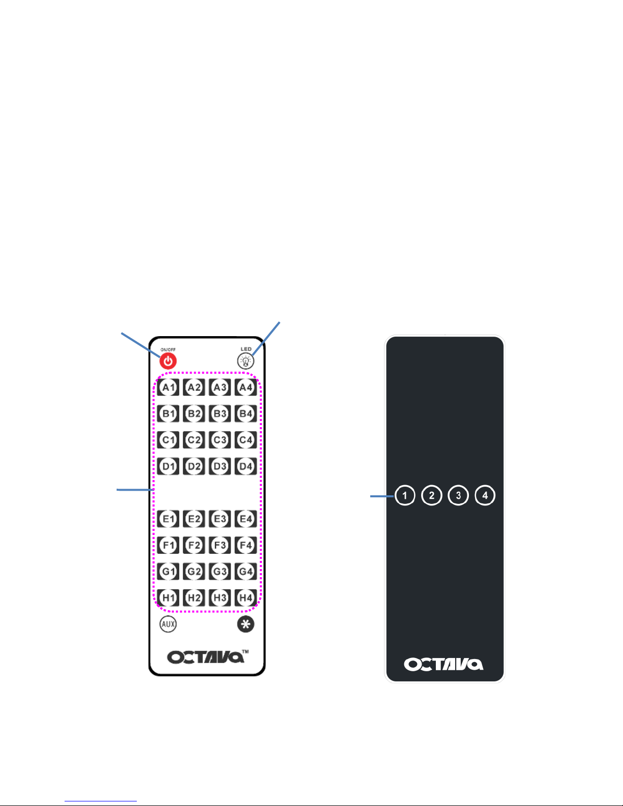
Remote Control Guide:
2 types of remotes are provided. Master Remote (Type C) and Zone Remote (Type D).
The Master Remote (Type C) can fully control the matrix from any zone or directly in front
of matrix
The Zone Remote (Type D) is a simplified remote only allowing user to switch inputs for
each zone. The Matrix can detect the location( Zone A-H) of the Zone Remote and will only
switch inputs for the detected Zone.
For example, user is located in Zone H and press 2 on the Zone Remote. The Matrix will
automatically set Output H to Input 2 without affecting the other Zones.
Turns On/Off the
HDMI Matrix
Input Selects
Example:
Press C3-changes
Output C to Input3
Turns on/off the Front LED
Display
Master Remote (Type C)
Zone Remote (Type D)
Input Select
Page 10
10
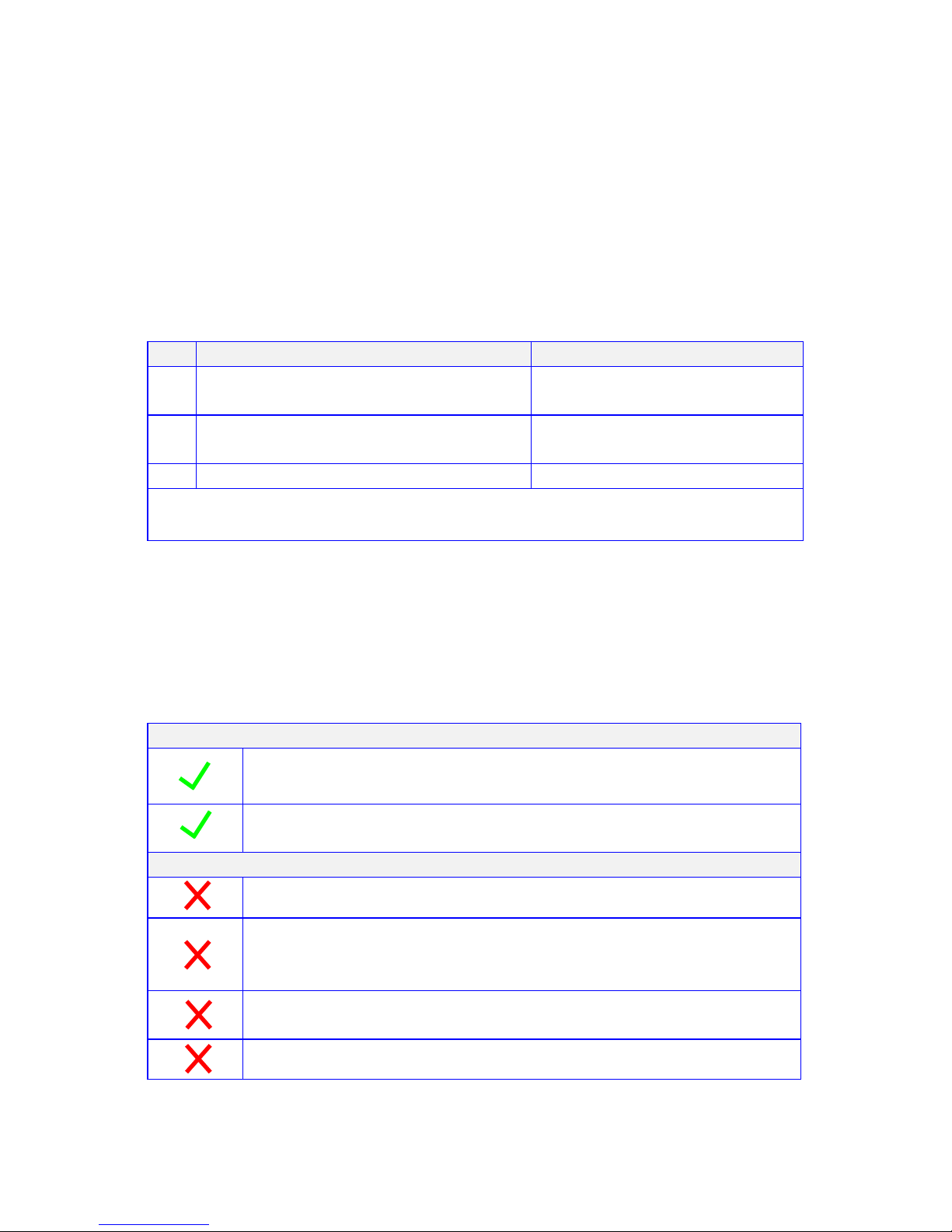
Ethernet cable recommendations:
Using shielded CAT6a or CAT7 cable will ensure maximum signal
integrity plus optimum rejection of external interference.
UTP CAT5 and CAT6 cables can be used with your Octava system
though they may result in limiting the maximum attainable distance
between the Matrix and the Rx unit when running HD signals.
Cable Type
Note
1
CAT 7 cable is recommended
Best
2
CAT6a cable is recommended
Good
3
UTP CAT 6 cable
For short links 100ft or less.
Use EIA/TIA-568-B standard when terminating your CAT5, CAT6 or
CAT7 cables.
Ethernet cable installation recommendations:
Use your cable suppliers recommended RJ-45 connector/crimp tool
with your CAT5, CAT6 or CAT7 cables and ensure you pay particular
attention to the quality of the termination on all cables.
DO / Recommend
Use shielded CAT6a or CAT 7 with good RJ-45 terminators
Use a direct cable connection between the Matrix and
Receiver unit.
DO NOT
Do Not connect thru Ethernet switches or routers
For optimum signal integrity avoid passing your signals
though any form of Patch-panel, wall-plate or punch-down
terminations
Do Not connect cables thru extraneous RJ-45 couplers,
wall plates.
Do Not tightly coil /loop the Ethernet cables
Page 11
11
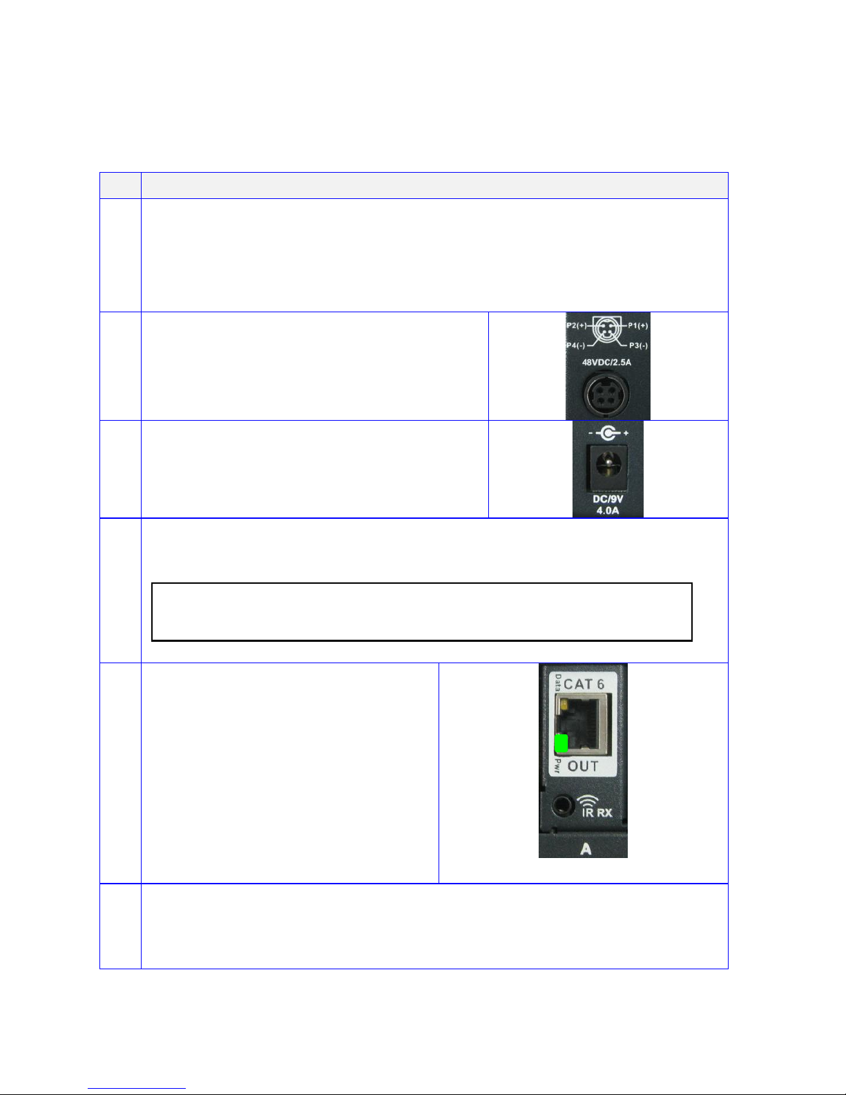
Installation:
Basic Installation
1
Disconnect ALL Power cables from the MATRIX
Disconnect ALL cables from the MATRIX / Zone Receivers
Power OFF all HDTV/Displays/Audio Receivers
Power OFF all Video Sources
Power OFF Matrix
2
Connect the 48VDC power supply to
matrix
3
Connect the 9VDC power supply to
matrix
4
Verify that the Matrix is turned on . Welcome screen as shown is
displayed
O C T A V A
5
Verify that the LED indicators on
the CAT6 outputs of the Matrix are
ON.
6
Please read the "Ethernet cable recommendations"
cabling recommendations on page 10 before proceeding
Continued on next page
Page 12

12
Connecting Output with CAT6 cables
7
Connect CAT6 output A to Zone
Receiver with CAT6a cable.
Verify that the LED Indicator are
illuminated as shown.
Pwr LED = solid green
Data LED = solid yellow
Note 1*
8
Connect HDMI output to Display
9
Repeat step 7 and 9 for all Zones
(Note 2*)
* Note 2: If re-connecting the CAT6 cable to the matrix or receiver.
Wait for at least 20 seconds before reconnecting the CAT6 cable to
ensure proper link.
Connecting HDMI sources /outputs and Audio Output
10
Turn OFF the Power to the Matrix
with remote
11
Connect HDMI sources to
HDMI IN 1-4
12
Connect HDMI Output A to
display or receiver with HDMI
cable. (optional)
13
Connect Audio outputs to Audio
system ( optional)
Reset System
14
Turn ON the matrix with remote
Done!
Page 13

13
IR Installation
I.R. Installation.
1
Insert IR Receiver cable to the
IR RX port of the Zone
Receiver HD70STP-RX as
shown.
2
Insert IR Emitter cable to the
IR Out ports of the Matrix
HD70STPMX as shown.
Connect a IR emitter cable to
the IR Broadcast port if you
need this feature.
3
Remove the double sided
tape on the IR Emitter
4
Locate the IR receiver on the
video source.
Place the Emitter head over
the source IR receiver
Page 14

14
EDID Configuration:
The Octava Matrix can be configured to 5 EDID settings.
It is recommended to keep the EDID in the default factory mode A.
*Custom EDID mode can be downloaded via USB and stored as
EDID mode E. Contact us for this feature.
To change the EDID settings, please see section “changing EDID
settings” for programming instructions.
Mode
Video
Audio
Description
A
480P,720 i/P, 1080 i/P
2 CH PCM,
Internal EDID
B
480P,720 i/P, 1080 i/P
2 CH PCM, Bitstream
(Dolby Digital, DTS)
Internal EDID
C
480P, 720 i/P, 1080 i/P,
+ 3D specifier
2 Ch PCM, Bitstream
(Dolby Digital, DTS)
Internal EDID
D
480P, 720 i/P, 1080 i/P,
+ 3D specifier
2 Ch PCM, Bitstream:
Dolby Digital, DTS
Dolby Tru HD,
DTS Master Audio
Internal EDID
E*
480P,720i/P, 1080 i
2 CH PCM
Internal EDID
OR
*Custom Mode
*Mode E is preset as 1080i, 2ch audio as shown in the table. For
customization, Mode E is replaced by the requested "custom EDID" via
USB programming.
8
Page 15

15
Changing EDID mode:
It is recommended to keep the EDID in the factory default MODE A. If
necessary, you may set to different EDID mode by following these
instructions. or view EDID Programming Instructions (video demo) at:
www.octavainc.com/support and updates.html
If you are unsure or need assistance, please contact us.
Action
Display
1
Press Home Button
O U T : A B C D E F G H
I N : 1 1 1 1 1 1 1 1
2
Press Menu Button
Goto EDID Menu
Reference Page 14 for EDID Modes.
E D I D S e l e c t P r e s s A , B , C , D o r E
3
Select EDID
A,B,C,D,or E
Press Cancel to exit
to previous screen
E D I D - A V i d = 4 8 0 - 1 0 8 0 P A u d = 2 c h P C M > E n t e
r
Example. EDID A shown
4
Press Enter to load
Press Cancel to exit
to previous screen
L o a d - A P r e s s E N T E R t o S T A R T
5
Wait for progress to
complete 100%
L o a d i n g E D I D A W a i t . . . P r o g r e s s : 0 0 0 %
6
Press Enter when
complete.
Done.
D o n e . P r e s s E N T E R
Page 16

16
Scene Select:
The HD4xSTPMX allows user to Quickly recall favorite Input/Output
configurations. The default preset scenes are shown below. The
scenes can be changed and programmed to meet your need.
Scene
IN/Out Configurations
A
All outputs connected to Input 1
P r o g r a m O u t : A B C D E F G H S c e n e - A I n : 1 1 1 1 1 1 1 1
B
All outputs connected to Input 2
P r o g r a m O u t : A B C D E F G H S c e n e - B I n : 2 2 2 2 2 2 2 2
C
All outputs connected to Input 3
P r o g r a m O u t : A B C D E F G H S c e n e - C I n : 3 3 3 3 3 3 3 3
D
All outputs connected to Input 4
P r o g r a m O u t : A B C D E F G H S c e n e - D I n : 4 4 4 4 4 4 4 4
Page 17

17
Scene Programming:
The scenes can be changed and programmed to meet your need.
Action
Display
1
Press Home Button
O U T : A B C D E F G H
I N : 1 1 1 1 1 1 1 1
2
Press Menu Button
Goto Scene Menu
S C E N E S E L E C T S e l e c t : A B C D
3
Select the Scene you
wish to configure
Press Cancel to exit to
previous screen
O u t : A B C D E F G H S c e n e A I n : 1 1 1 1 1 1 1 1 > E n t e
r
Example. Scene A shown
4
Press Menu to enter
program mode
Press Cancel to exit to
previous screen
P r o g r a m O u t : A B C D E F G H S c e n e - A I n : 1 1 1 1 1 1 1 1
5
Use the Octava
Remote control to
program the Scene for
your preference.
Example:
Programming Scene A
Out A,E = 1
Out B.F= 2
Out C,G= 3
Out D,H= 4
P r o g r a m O u t : A B C D E F G H S c e n e - A I n : 1 2 3 4 1 2 3 4
Use the Octava Remote Control to
program the scenes
6
Press Enter when
complete. The Scene
has now been saved.
Done.
D o n e . P r e s s E N T E R
Page 18

18
USB Service Port:
The USB port is for service ,EDID updates or customization requests
Contact us for this feature or visit out support page for more info
www.octavainc.com/support and updates.html
Page 19

19
Serial Control:
The HD4XSTP can be controlled by serial commands. Serial
commands can be sent to the HD4xSTP by :
1) RS-232 port ( default)
OR
2) LAN port
Display
1
Press Menu Button
Goto Serial Control
Port Menu
S e r i a l C o n t r o l P o r t > E n t e
r
Indicates Serial Control will be via RS-232 Port
2
Select A to control
matrix via RS-232
port
Select E to control
matrix via LAN
Control Port
R S - 2 3 2 ( D B - 9 ) P r e s s A L A N ( R J 4 5 ) P r e s s E
Display
Indicates Serial Control will
be via RS-232 Port
RS-232 Control
O U T : A B C D E F G H I N : 1 1 1 1 1 1 1 1
Indicates Serial Control will be via RS-232 Port
Indicates Serial Control will
be via LAN Port
LAN Port
O U T : A B C D E F G H * L A
N
I N : 1 1 1 1 1 1 1 1
Indicates Serial Control will be via LAN Port
Page 20

20
Serial Control RS-232 Control Setup:
The Matrix can be easily integrated with 3rd Party control systems via
RS232 control. The following shows the RS-232 pin out and control
protocol for controlling the Matrix.
RS-232 Port
Pin 2
Receive Data
Pin 3
Transmit Data
Pin 5
Signal Ground
Serial Port Setting
Baud Rate
9600
Data Bits
8
Parity Check
none
Stop Bits
1
Flow control
none
1 5 6 9 2
3
Page 21

21
Serial Control Via LAN Port Control Setup:
The LAN /Ethernet port can be used to control the matrix. A Moxa
NE-4100 embedded device servers is used to achieve this. The
NE-4100 support 10/100 Mbps Ethernet, and provide ready-to-use
operation modes, including TCP Server, TCP Client, and UDP. This
devices enables sending serial commands to the HD4XSTPMX using
the LAN port. Once connected, and configured the RS-232
commands can be sent to control the HD4xSTPMX.
Complete detail instructions on using the NE-4100 can be found
here:
http://www.moxa.com/doc/manual/NE/4100/v6/NE-4100_Series_Use
rs_Manual_v6.pdf
To Use the LAN port for serial control you may follow these
instructions.
Step
Serial Control Via LAN Port
1
Connect Ethernet cable to the LAN Port of the Matrix and
your LAN
2
Set Matrix to LAN serial port control. See page 19
3
Download and Install "NPort Windows Driver Manager
(WHQL certified)"on the PC that will be used to control the
matrix.
Download Link below:
NPort Windows Driver Manager
http://www.moxa.com/support/download.aspx?id=974
4
Open and Run the "NPort Driver Manager"
Continued on next page...
Page 22

22
Step
Serial Control Via LAN Port
5
Click "ADD"
6
Click "Search"
Continued on next page...
Page 23

23
Step
Serial Control Via LAN Port
7
Wait for Search to complete.
Make sure a device is found. If not, repeat step 1~6
8
Click “OK”
9
Click “Yes” on the notification
Wait until activation is complete
10
Click “OK” on the notification
Continued on next page...
Page 24

24
Step
Serial Control Via LAN Port
11
Note the COM Port and IP Address Assigned as shown on
your program screen.
12
Write down the COM Port =
Write down the IP Address =
.
13
Open “Local Area Connection Properties”
Double click on “Internet Protocol Version 4 (TCP/IPv4)
Continued on next page...
assigned
Com Port
IP address of
Moxa Serial server
Page 25

25
Serial Control Via LAN Port
14
Choose “Use the following IP address:
15
-Key in the first 3 numbers from “Address 1” found in Step 12 for
“IP address:” Enter "199" or some unused number for the 4th
octet.
-Key in 255.255.255.0 for “Subnet mask:”
-Click “OK”
Done! Use your Control Program and select the COM Port
Assigned by Nport Driver Manger to control the Matrix.
Serial commands are on page 26
see step 11
Enter "199" or an unused
octet. Can not be same
as the last octet of the IP
address assigned to the
Moxa serial server
shown in Step 11.
Page 26

26
Serial Commands- (Basic):
Controlling the Matrix via RS232 can be done by send a series of
commands per the RS232 Command Table
Basic controls
Note: The commands are in HEX. No spaces between HEX codes.
“0x” denotes HEX. No need to enter “0x”
HEX CODE
Port Status
0x02 0x30 0x30 0x31 0x03
Turn ON LCD
0x02 0x30 0x30 0x33 0x03
Turn OFF LCD
0x02 0x30 0x30 0x34 0x03
Turn ON Power
0x02 0x30 0x30 0x35 0x03
Turn OFF Power
0x02 0x30 0x30 0x36 0x03
Example:
To turn off LED , send Command:
0230303403 in Hex
Note: The commands are in HEX. No spaces between HEX
codes.“0x” denotes HEX. No need to enter “0x”
Page 27

27
Serial Commands- (switching):
Switching Commands
Note: The commands are in HEX. No spaces between HEX codes.
“0x” denotes HEX. No need to enter “0x”
Output A Switching Commands
HEX CODE
Switch OUT A to Input port 1
0x02 0x32 0x31 0x31 0x03
Switch OUT A to Input port 2
0x02 0x32 0x31 0x32 0x03
Switch OUT A to Input port 3
0x02 0x32 0x31 0x33 0x03
Switch OUT A to Input port 4
0x02 0x32 0x31 0x34 0x03
Output B Switching Commands
Switch OUT B to Input port 1
0x02 0x32 0x32 0x31 0x03
Switch OUT B to Input port 2
0x02 0x32 0x32 0x32 0x03
Switch OUT B to Input port 3
0x02 0x32 0x32 0x33 0x03
Switch OUT B to Input port 4
0x02 0x32 0x32 0x34 0x03
Output C Switching Commands
Switch OUT C to Input port 1
0x02 0x32 0x33 0x31 0x03
Switch OUT C to Input port 2
0x02 0x32 0x33 0x32 0x03
Switch OUT C to Input port 3
0x02 0x32 0x33 0x33 0x03
Switch OUT C to Input port 4
0x02 0x32 0x33 0x34 0x03
Output D Switching Commands
Switch OUT D to Input port 1
0x02 0x32 0x34 0x31 0x03
Switch OUT D to Input port 2
0x02 0x32 0x34 0x32 0x03
Switch OUT D to Input port 3
0x02 0x32 0x34 0x33 0x03
Switch OUT D to Input port 4
0x02 0x32 0x34 0x34 0x03
Output E Switching Commands
Switch OUT E to Input port 1
0x02 0x32 0x35 0x31 0x03
Switch OUT E to Input port 2
0x02 0x32 0x35 0x32 0x03
Switch OUT E to Input port 3
0x02 0x32 0x35 0x33 0x03
Switch OUT E to Input port 4
0x02 0x32 0x35 0x34 0x03
Output F Switching Commands
Switch OUT F to Input port 1
0x02 0x32 0x36 0x31 0x03
Switch OUT F to Input port 2
0x02 0x32 0x36 0x32 0x03
Switch OUT F to Input port 3
0x02 0x32 0x36 0x33 0x03
Switch OUT F to Input port 4
0x02 0x32 0x36 0x34 0x03
Page 28

28
Output G Switching Commands
HEX CODE
Switch OUT G to Input port 1
0x02 0x32 0x37 0x31 0x03
Switch OUT G to Input port 2
0x02 0x32 0x37 0x32 0x03
Switch OUT G to Input port 3
0x02 0x32 0x37 0x33 0x03
Switch OUT G to Input port 4
0x02 0x32 0x37 0x34 0x03
Output H Switching Commands
Switch OUT H to Input port 1
0x02 0x32 0x38 0x31 0x03
Switch OUT H to Input port 2
0x02 0x32 0x38 0x32 0x03
Switch OUT H to Input port 3
0x02 0x32 0x38 0x33 0x03
Select OUT H to Input port 4
0x02 0x32 0x38 0x34 0x03
Select ALL Output Switching
Commands
Switch ALL Outputs(A-H) to Input port 1
0x02 0x32 0x39 0x31 0x03
Switch ALL Outputs(A-H) to Input port 2
0x02 0x32 0x39 0x32 0x03
Switch ALL Outputs(A-H) to Input port 3
0x02 0x32 0x39 0x33 0x03
Switch ALL Outputs(A-H) to Input port 4
0x02 0x32 0x39 0x34 0x03
Scene Select Commands
Switch to Scene A
0x02 0x32 0x30 0x31 0x03
Switch to Scene B
0x02 0x32 0x30 0x32 0x03
Switch to Scene C
0x02 0x32 0x30 0x33 0x03
Switch to Scene D
0x02 0x32 0x30 0x34 0x03
Page 29

29
Serial Commands- (Forwarding):
The HD4xSTPMX can route commands from the RS-232
port to any connect Zones A-H for controlling the attached display
The Forwarding protocol is shown here:
STX
Data Rate
Zone
# of bytes
ETX
Start of
text(0x02)
9600bps (0x41)
A(0x31)
1(0xA1)
End of text
(0x03)
19200bps (0x42)
B(0x32)
2(0xA2)
38400bps (0x43)
C(0x33)
3(0xA3)
57600bps (0x44)
D(0x34)
4(0xA4)
E(0x35)
5 (0xA5)
F(0x36)
6 (0xA6)
G(0x37)
7 (0xA7)
H(0x38)
8 (0xA8)
9 (0xA9)
10(0x10)
11(0x11)
12(0x12)
...
99(0x99)
Example:
To send a 9600 baud, 10 byte command to Zone H.
Step1: Send RS-232 Forwarding Command to matrix. This will set up the
matrix to "forward" the next 10 Byte command to Zone H at 9600baud.
STX
Data Rate
Zone
# of bytes
ETX
9600 Bps
Zone H
10 bytes
0x02
0x41
0x38
0x10
0x03
Step 2: Send the 10 byte commands that you wish to pass to Zone H.
Byte1
Byte2
Byte3
Byte4
Byte5
Byte6
Byte7
Byte8
Byte9
Byte10
Done.
The RS-232 port will remain connected to the requested Zone for 1 second
after command has been sent (step 2). This allows for any reply to be
received from the zones.
After 1 sec, all zones will be disconnected from RS-232
Page 30

30
Zone Receiver Serial Data (RS-232) Port:
The HD4xSTPMX can route commands from the RS-232
port to any connect Zones A-H for controlling the attached display
A 3 pin Phoenix connector is provided to connect with a RS-232
serial cable.
RS-232 / Phoenix Cabling:
1. Remove insulation from RS-232 serial cable
2. Insert TX, RX, Gnd wire to the 3 pin Phoenix connector.
3. Use screwdriver to secure the wire to the 3 pin Phoenix connector
Serial Port cable
( Zone RX side)
HD70STP-RX
3 pin Phoenix connector
Page 31

31
Installing Transmitter Output cards :
The HD4xSTPMX has configurable outputs allowing user to install
additional cards.
Procedure
1
Disconnect 48VDC and 9VDC power supply from the Matrix.
2
Disconnect ALL cables from the matrix
3
Remove the TX card thumb screws.
4
Remove cover screws (x13) with screw driver
5
Remove cover
Continued on next page...
Step1
Step 2
remove all
cables from
matrix
Step 3
Step 4
Step 5
Page 32

32
Procedure(cont'd)
6
Remove the blank cover plate for the Output slot you wish to add.
Out E shown.
7
Install the TX card to the slot
8
Install top cover back on matrix
9
Tighten TX card thumb screws.
10
Install the cover Screws (x13) with Philips screw driver
11
Done
Goto page 11 for instruction on installing the matrix.
Step 6
Step 7
Step 8
Step 9
Step 10
Page 33

33
Description
Specifications
Model
HD4xSTPMX
HDMI Inputs
4
RJ45 Outputs
8 Maximum. User configured by installing 1 to 8 output cards. Up to
8 Zones.
Link Distance RJ45
Outputs
200ft (60m) , CAT6 or CAT7 cable recommended.
HDMI Outputs
1 (mirrors Zone A Card Frame output)
Digital Audio Outputs
1 (mirrors Zone A Card Frame output)
Video Resolution
1080P (60/50/24) , 720p(60/50), 1080i (60/50), current 3D
consumer formats plus 4K.
Power over Ethernet ( PoE)
Power the Zone Receivers via your CAT 6 cables.
IR Control
IR control of the Matrix, x4 Sources (Routed) plus an AVR from
Zone receivers.
Wideband IR 20-60 KHz circuitry for maximum IR remote
compatibility using Octava supplied IR cables.
RS-232
Control the Matrix using serial commands or 3rd party control
software (HEX commands available)..
Serial Commands can also be routed to the connected Zone
receivers via your CAT6 cables to control your HD Displays.
USB
USB port provided : Firmware updates, customization and for
service.
LAN /IP Port
LAN port provided for: Firmware updates, customization and
control..
Control
Front Panel buttons, Serial Port, LAN Port, or IR Control.
EDID Management
5 common EDID selections provided. Customized EDID also
available and can be downloaded to matrix using USB or LAN port.
Dimensions
Matrix : 18.9 x 10.94 x 3.47 in (L x W x H) (48.0 x 27.8 x 8.82cm).
2RU
Receiver : 4.53 x 3.19 x 1.14 in ( L x W x H) (11.5 x 8.1 x 2.9cm)
19” Rack Mounts
Integrated.
Power Supply
1 x 9VDC (Matrix) and 1 x 48VDC (Zone Receivers) included
Page 34

34
Rev.A
Warranty
Octava warrants the equipment purchased to be free from defects in
material and workmanship under normal use and service for a period of 1
year. In the event applicable law imposes any implied warranties, the
implied warranty period is limited to 1 year from the date of receipt.
If Octava's equipment fails because of defects (1) year from the date of
receipt, Octava will at its option, A) repair or replace the equipment, or B)
request return of equipment for refund of the price paid for the product
provided that the equipment has not been subjected to mechanical,
electrical or other abuse or modifications.
Proof of sale required to claim warranty.
Disclaimers
IN NO EVENT SHALL OCTAVA'S OR ITS SUPPLIER’S LIABILITY FOR
ANY CLAIM WHATSOEVER EXCEED THE COST OF THE PRODUCTS
GIVING RISE TO THE CLAIM, WHETHER BASED IN CONTRACT,
WARRANTY, INDEMNITY OR TORT (INCLUDING, WITHOUT
LIMITATION, NEGLIGENCE AND STRICT LIABILITY) OR OTHERWISE.
IN NO EVENT SHALL OCTAVA INC. OR ITS SUPPLIERS BE LIABLE
FOR ANY SPECIAL, INCIDENTAL, CONSEQUENTIAL OR OTHER
INDIRECT DAMAGES (INCLUDING, WITHOUT LIMITATION, LOSS OF
REVENUES, PROFITS OR OPPORTUNITIES), HOWEVER CAUSED, ON
ANY THEORY OF LIABILITY, WHETHER OR NOT OCTAVA INC HAS
BEEN ADVISED OF THE POSSIBILITY OF SUCH DAMAGES.
WHILE EVERY PRECAUTION HAS BEEN TAKEN IN THE
PREPARATION OF THIS MANUAL, OCTAVA ASSUMES
NO RESPONSIBILITY FOR ERRORS OR OMISSIONS. IN NO
EVENT WILL OCTAVA ASSUME ANY LIABILITY FOR DAMAGES
RESULTING FROM THE USE OF THEINFORMATION CONTAINED HEREIN.
OCTAVA RESERVES THE RIGHTTO CHANGE THE SPECIFICATIONS,
FUNCTIONS OR CIRCUITRY OFTHE PRODUCT WITHOUT NOTICE.
For Questions and support:
Email : info@octavainc.com
URL: www.octavainc.com
Copyright© 2013 Octava Inc. All rights reserved.
HDMI, the HDMI logo and High-Definition Multimedia Interface are trademarks
or registered trademarks of HDMI Licensing LL.C
All trademarks are the sole property of their respective companies
 Loading...