


1
Installation Guide
Model: HD42CATMX
PRO HD HOME THEATER SERIES

2
Contents
Application Diagram ........................................................ 3
Features .......................................................................... 3
Matrix Overview ...................................................................... 4
Infrared Overview ................................................................... 5
Zone Receiver (RX) Overview.............................................. 6
Identifying Zone Receiver (RX) ............................................ 7
Powering the PoC Zone Receiver ....................................... 8
Powering non-PoC Zone Receiver ...................................... 8
Ethernet cable recommendations ........................................ 9
Ethernet cable installation recommendations .................... 9
Installation ..................................................................... 10
Front Panel Control ....................................................... 13
Remote Control Guide .................................................. 13
EDID Switch .......................................................................... 14
USB Service Port............................................................14
EDID Configuration ....................................................... 15
Changing EDID mode.....................................................16
RS232 Controls Commands...........................................18
1 RU Rackmount.............................................................20
Disabling / Enabling IR Remote Receiver.......................20
Warranty..........................................................................21
Disclaimers......................................................................21
Specifications..................................................................22

3
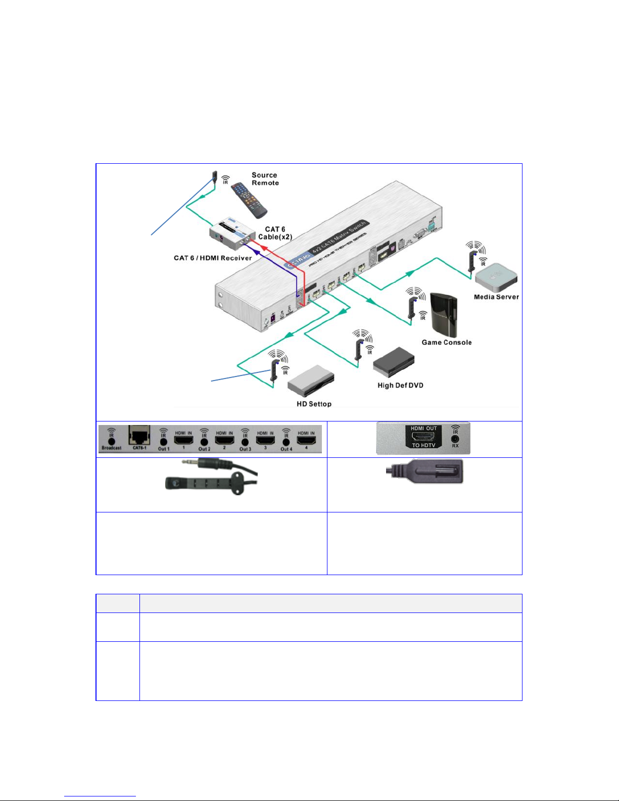
Application Diagram
Features:
Non-blocking Matrix – view Any Source on Any Display
View any 4 Source devices simultaneously on 2 ‘Remote
display devices + 1 Local "mirrored" HDMI output.
Supports 1080p24, 1080p60, 1080p50 plus current consumer
3D formats.
4 HDMI inputs
1 HDMI Output (mirrored)
2 Dual RJ-45 Extender Outputs.
HDMI and CAT RJ-45 active simultaneously
Routed IR from remote Zones to control Matrix plus Source
devices.
Broadcast IR from remote Zones to control AV Receiver.
PoC (Power over Cable) to directly power in-room Zone
receivers via RJ-45 from matrix.
EDID Management plus custom EDID via USB service port.
Rack mountable (1 RU) – mounting lugs supplied.
Discrete IR codes for simple system integration.
Wired IR port for In-cabinet installations.
RS232 port for PC or Control System operation.
Compatible with Octava PoC low profile In-room
Receiver units.
4
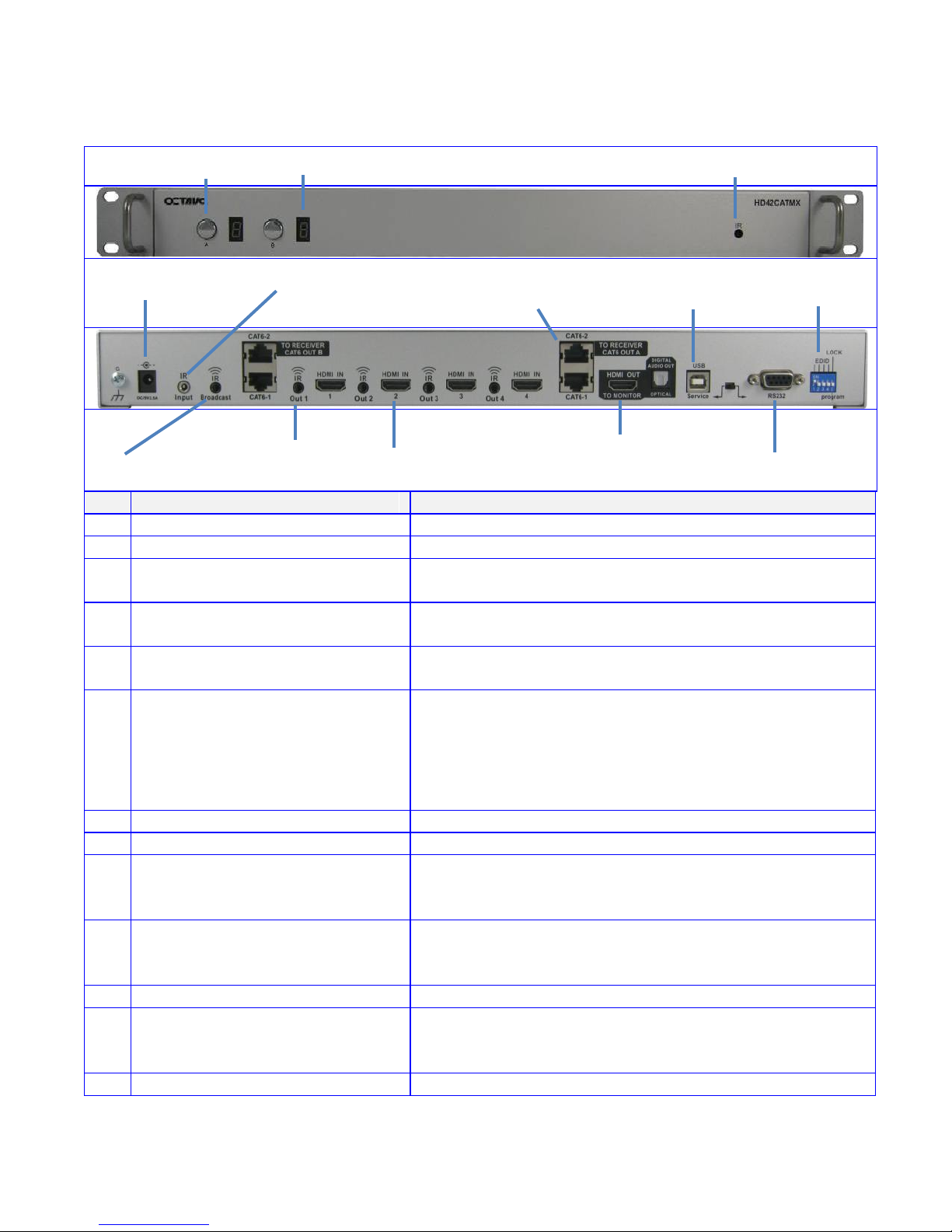
Matrix Overview:
Item
Description
1
Input Select
Press to select Source device
2
Led Display
Indicates selected Source device.
3
IR Receiver
Control Matrix using Octava remote.
4
Power Input 5v
provides power to Matrix and PoC compatible Zone
Receiver (Rx) units
5
Wired IR input
connect Octava supplied IR Receiver Extension
cable(optional)
6
IR Broadcast Port. All IR
signals received from the
zone receivers can be sent
out thru the IR Broadcast
port
connect Octava supplied IR Transmitter Blaster
cable(optional)
7
IR Output (1-4)
connect Octava supplied IR Transmitter Blaster cable
8
HDMI Input (1-4)
connect High Speed HDMI cables to Source device.
9
HDMI Output
connect High Speed HDMI cables to AVR or Display
device.
10
Dual RJ-45 Output (A-B)
CAT-6
connect Twisted Pair cables (x2) to Octava Zone
Receiver (Rx) unit.
11
USB Port
for custom EDID/ code updates
12
RS232 Port
for external control of Matrix via PC or proprietary
Control system.
13
EDID DIP Switch(1-5)
set Matrix EDID modes
1-Input Select
2-Led Display
3- IR Receiver
7- IR Output (1-4)
5- Wired IR input
8- HDMI Input (1-4)
9- HDMI Output
10- Dual RJ-45 Output
(A-B) CAT-6
11-USB port
13-EDID DIP
switch(1-5)
12-RS-232 control
4 - Power Input 5v
6- IR Broadcast Port
5
Infrared Overview:
-IR can be independently Routed from any of the 2 connected Zones
back to the Matrix plus connected Source devices.
-All IR signals received from the zone receivers can be sent out thru
the IR Broadcast port by connecting an IR Transmitter cable.
connect to IR Output (1-4) on
Octava Matrix. Connect a IR
transmitter cable to the IR Broadcast
port if you need this feature.
connect to IR Input on Octava
Zone Receiver (Rx) unit.
Step
IR Installation
1
Connect an Octava supplied IR Receiver cable to each Zone Rx unit.
2
Connect an Octava supplied IR Blaster cable from the IR Output Port
(1-4) on the Octava Matrix and position the Blaster Head over the IR
Receiver window on the connected Source device. Connect IR
transmitter cable to the IR Broadcast port if feature needed.
14- IR Transmitter
/Blaster cable
15- IR Receiver cable
14-IR BlasterTransmitter cable
15-IR Receiver cable
6
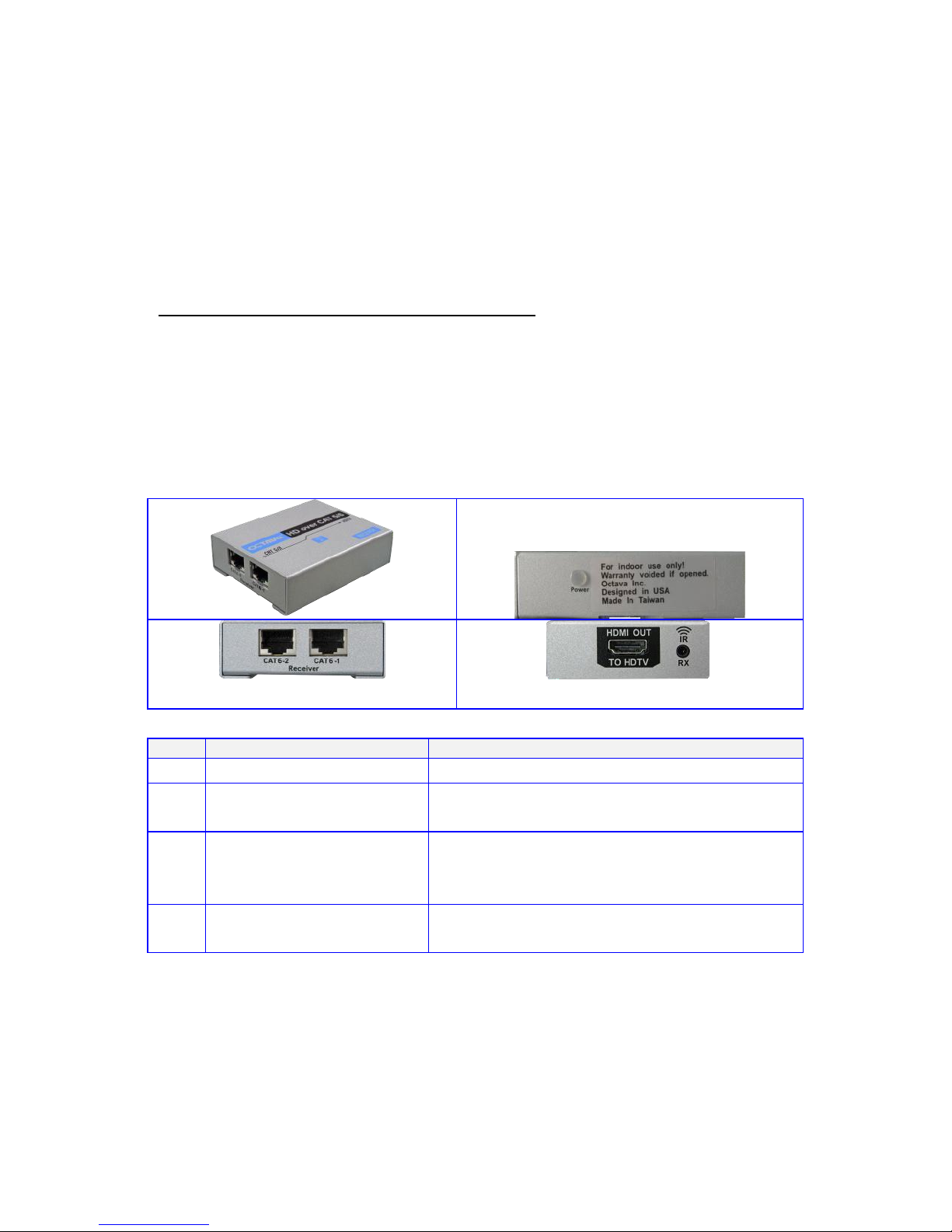
Zone Receiver (RX) Overview:
A Zone Rx unit is positioned close to your Display device and
connected to the Octava Matrix via 2xTwisted Pair (CAT5 or CAT6)
cables. Connect the Rx unit to your Display device using a short High
Speed HDMI cable.
Before you begin your system installation please ensure you identify
which type of Octava Rx unit you are working with – PoC, non-PoC.
Refer to section: “Identifying Zone Receiver (RX)”
PoC (Power over Cable) Rx units are powered from the Matrix
non-PoC Rx units require a local 5V power supply
Item
Description
16
Power Indicator
indicates Rx is receiving power
17
RJ-45 Input (1-2).
connect to CAT6 Out (-1 -2) on Zones
A-D of Octava Matrix
18
HDMI Out to HDTV
connect to HDTV using High Speed
HDMI cable
19
IR receiver
connect Octava supplied IR Receiver
cable.
16-Power Indicator
19- IR receiver input
18- HDMI Out to HDTV
17- CAT 6 Input
7
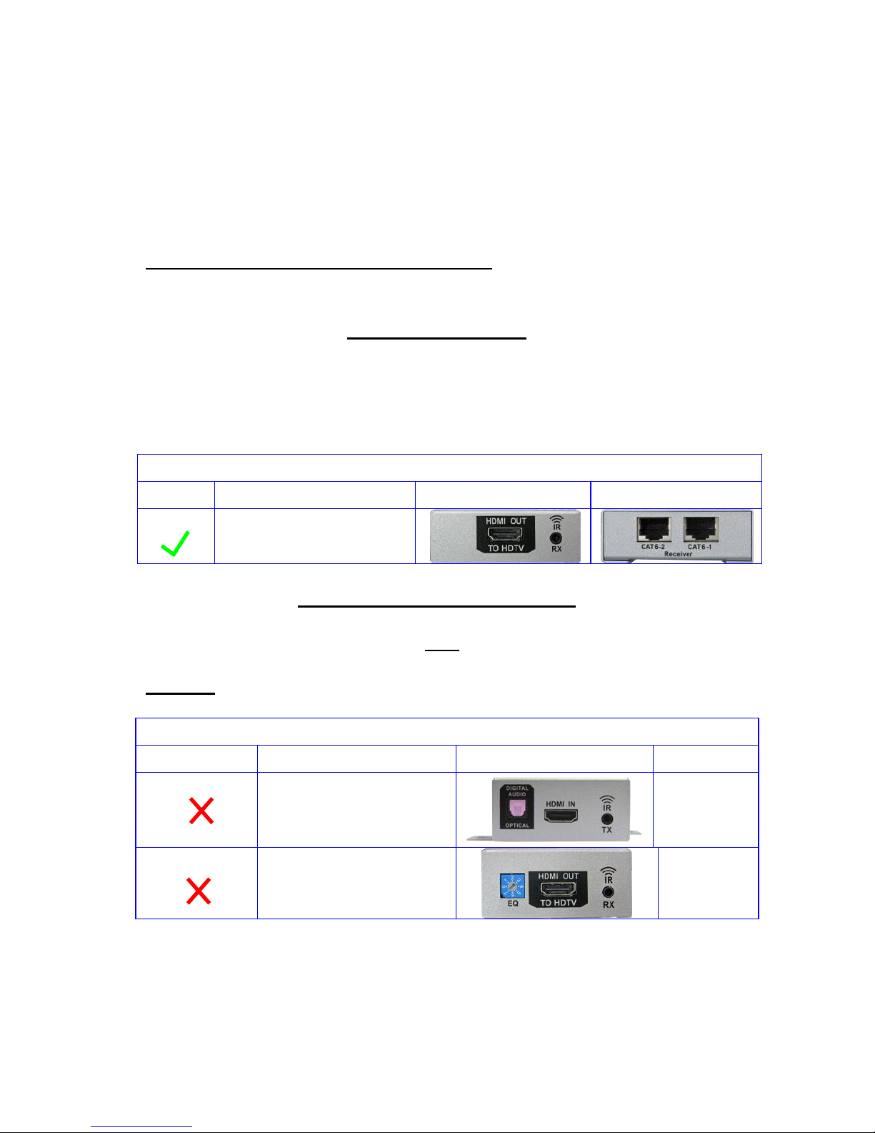
Identifying Zone Receiver (RX)
The Octava matrix features Power Over Cable ( PoC). PoC enables
the Matrix to power the PoC Zone Receiver units directly, using the
PoC power supply.
Before you begin your system installation please ensure you identify
which type of Octava Rx unit you are working with – PoC, non-PoC.
PoC Zone Receiver:
The Octava Matrix should include CAT 6 receivers with PoC.
(power over cable). Please verify by inspecting the first 6 serial
number and confirm it is: RXH3IR
PoC Zone Receivers:
Serial Number
PoC
RXH3IRXXXXXX
NON- PoC Zone Receiver (RX):
If you are upgrading or replacing only the matrix, the Zone Receiver
you installed may be older. The Zone Receivers in the following table
do NOT have PoC. capability.
non PoC
Serial Number
NO PoC
RXHIRXXXXXX
NO PoC
RXH2IRXXXXXX
If you are unsure or need assistance, please contact us.

8
Powering the PoC Zone Receiver:
Power Over Cable ( PoC) enables the Matrix to power the PoC Zone
Receiver units directly, using the PoC power supply.
PoC – Zone Rx is powered via the connected Twisted Pair cables
(CAT5 or CAT6) from the PoC power supply connected to the PoC
socket on the Matrix.
Matrix PoC Power Port
PoC Zone Receiver
connect Octava supplied PoC power
supply (5V, 2.5A)
local power supply not
required.
Powering non-PoC Zone Receiver:
non-PoC – Zone Rx is powered by a local 5V PSU connected to the
Power Socket on the Rx unit.
Matrix PoC Power Port
non-PoC Zone Receiver
local power supply not required.
connect Octava supplied 5V
PSU to Rx unit power socket
If you are unsure or need assistance, please contact us.

9
Ethernet cable recommendations:
Using Shielded, Stranded CAT6 or CAT7 cable will ensure maximum
signal integrity plus optimum rejection of external interference.
UTP CAT5 and CAT6 cables can be used with your Octava system
though they may result in limiting the maximum attainable distance
between the Matrix and the Rx unit when running HD signals.
Cable Type
Note
1
CAT 7 cable is recommended
Best
2
Shielded CAT 6 cable is recommended
Good
3
UTP CAT 6 cable
For short links 50ft or
less.
Use EIA/TIA-568-B standard when terminating your CAT5, CAT6 or
CAT7 cables.
Ethernet cable installation recommendations:
Use your cable suppliers recommended RJ-45 connector/crimp tool
with your CAT5, CAT6 or CAT7 cables and ensure you pay particular
attention to the quality of the termination on all cables.
DO/Recommend
Use shielded CAT 6 or CAT 7 with good RJ-45 terminators
Use a direct cable connection between the Matrix and
Receiver unit.
DO NOT
Do Not connect thru Ethernet switches or routers
For optimum signal integrity avoid passing your signals
though any form of Patch-panel, Wall-plate or punch-down
terminations
Do Not connect cables thru extraneous RJ-45 couplers,
wall plates.
Do Not tightly coil /loop the Ethernet cables

10
Installation:
Step
0
Disconnect ALL cables from the MATRIX / Zone Receivers
Power OFF all HDTV/Displays/Audio Receivers
Power OFF all Video Sources
Power OFF Matrix
Power OFF Zone Receivers
1
Verify that the Configuration Switch
is set to the factory default mode.
2
Connect HDMI sources to
HDMI IN 1-4
Connecting Output with HDMI
cable
3
If you are connecting with HDMI
cable:
Connect HDMI cable to
HDMI output A and HDTV
Connecting Output with Ethernet
cables
4
Verify that the Zone Receiver you
have supports PoC (See page 7)
If the Zone Receiver has PoC
proceed to step 5.
IF your Zone Receiver are
non PoC proceed to
Alternative steps A1-A5.
(Skip to page 12)
5
Connect the 5VDC power supply to
the DC/5V port.
HDMI Out
CONTINUE on Next Page

11
6
Connect CAT6 -1 of Matrix and
Receiver with CAT 6 cable.
Connect CAT6 -2 of Matrix and
Receiver with CAT 6 cable.
7
Verify the Power LED Indicator is On.
If not, please check your
connections.
Note: the 5V power of Receiver is
not used for Matrix powered by
P.O.C.
8
Connect HDMI output of Receiver to
HDTV
To HDTV
9
Install I.R. receiver cable.
Install I.R. transmitter cable
See page 5 “infrared
overview”
10
Verify the Matrix LED Display turns
on and displays 1.
11
Power ON HDTV
Power ON Source
Done.
If you are unsure or need assistance, please contact us.

12
Alternative Steps A1-A6 are only for installations with
non PoC Zone Receivers.
A1
Connect CAT6 -1 of Matrix and
Receiver with CAT 6 cable.
Connect CAT6 -2 of Matrix and
Receiver with CAT 6 cable.
A2
Connect 5 V power to the Zone
Receiver
Verify the Power LED Indicator is
On.
Connect to 5V power
supply
A3
Connect HDMI output of Receiver
to HDTV
To HDTV
A4
Install I.R. receiver cable.
Install I.R. transmitter cable
See page 5 “infrared
overview”
A5
Verify the Matrix LED Display turns
on and displays 1.
A6
Power ON HDTV
Power On Source
Done.
If you are unsure or need assistance, please contact us.
Non PoC receiver

13
Front Panel Control:
Directly press the select buttons to change inputs.
For example:
To set Output A to Input 2. Simply press the A button until the
LED displays 2.
Remote Control Guide:
Turns On/Off the
HDMI Matrix
Turns on/off the Front
LED Display
Input Select
Example:
Press B3-changes
Output B to Input3
C-H Not used for
HD42CATMX
Firmware code
revision #

14
EDID Switch:
The EDID switch is used to program the Matrix into various EDID modes.
Switch
Number
1 2 3 4 5
Name
EDID
switch
EDID
switch
EDID
switch
EDID
switch
Program/LOCK
switch
Function
EDID
MODE
select
EDID
MODE
select
EDID
MODE
select
EDID
MODE
select
Program/LOCK
switch
Down= Program
mode
Up= Locked
USB Service Port:
The USB port is for service and EDID updates if needed.
Contact us for this feature.

15
EDID Configuration:
The Octava Matrix can be configured to 5 EDID settings.
It is recommended to keep the EDID in the default factory mode 1.
*Custom EDID mode can be downloaded via USB. Contact us for
this feature.
To change the EDID settings, please see section “changing EDID
settings” for programming instructions.
Mode
Video
Audio
Description
Switch settings
1
480P,720 I/P,
1080 I/P
2 CH PCM,
Bitstream
(Dolby Digital,
DTS)
Default
Mode.
[Internal
EDID]
2
Read EDID of all
monitors/receivers
and set:
Video=Minimum
Resolution of
devices
connected.
Read EDID of all
monitors/receivers
and set:
AUDIO =Maximum
capability of
devices connected.
[External
EDID]
3
480P,720 I/P,
1080 I
2 CH PCM
Basic
Mode.
[Internal
EDID]
4
480P, 720 I/P,
1080 I/P, + 3D
specifier
2 Ch PCM,
Bitstream
(Dolby Digital,
DTS)
3D Mode.
[Internal
EDID]
5
480P,720 I/P,
1080 I/P
2 CH PCM
[Internal
EDID]
*Custom
Mode
8

16
Changing EDID mode:
It is recommended to keep the EDID in the factory default MODE1.
If necessary, you may set to different EDID mode by following these
instructions or view EDID Programming Instructions (video demo) at:
www.octavainc.com/support and updates.html
If you are unsure or need assistance, please contact us.
Step
Action
Notes
1
Disconnect all
sources and display
from Matrix
2
Set switch 1,2,3,4,5
to down position as
shown
3
Set the EDID to the
mode desired.
(MODE 2 shown.)
See page 15
“EDID
Configuration”
for other EDID
modes
4
Reset Power to the
Matrix by
disconnecting the
power and
reconnecting power.
5
The LED will now
indicate the EDID
Mode that you will
program.(mode 2
shown)
1= mode 1
2= mode 2
3= mode 3
4= mode 4
5= mode 5
flashed
CONTINUE on Next Page

17
6
Press the A button
on the front panel.
LED will count from
00 to 99 while
programming.
LED will count
from 00 to 99
while
programming.
7
Wait.
Programming is
complete when LED
indicates “1”
8
Set to LOCK
Position
9
Connect all video
sources and
displays and turn
ON
10
Reset Power to the
Matrix by
disconnecting the
power and
reconnecting power.
If you are unsure or need assistance, please contact us.

18
RS-232 Control Commands
The Matrix can be easily integrated with 3rd Party control systems via
RS232 control. The following shows the control protocol for
controlling the Matrix.
RS-232 protocol
Baud Rate
9600
Data Bits
8
Parity Check
none
Stop Bits
1
Flow control
none
Controlling the Matrix via RS232 can be done by send a series of
commands per the RS232 Command Table
Basic controls
Note: The commands are in HEX. No spaces between HEX codes.
“0x” denotes HEX. No need to enter “0x”
HEX CODE
Port Status
0x02 0x30 0x30 0x31 0x03
Turn ON LED
0x02 0x30 0x30 0x33 0x03
Turn OFF LED
0x02 0x30 0x30 0x34 0x03
ON
0x02 0x30 0x30 0x35 0x03
OFF /"soft " Standby
0x02 0x30 0x30 0x36 0x03
Example:
To turn off LED , send Command:
02 30 30 34 03 in Hex
Set the switch to RS-232 side as
shown.

19
Switching Commands
Note: The commands are in HEX. No spaces between HEX codes.
“0x” denotes HEX. No need to enter “0x”
Output A Switching Commands
HEX CODE
Select OUT A to Input port 1
0x02 0x32 0x31 0x31 0x03
Select OUT A to Input port 2
0x02 0x32 0x31 0x32 0x03
Select OUT A to Input port 3
0x02 0x32 0x31 0x33 0x03
Select OUT A to Input port 4
0x02 0x32 0x31 0x34 0x03
Output B Switching Commands
Select OUT B to Input port 1
0x02 0x32 0x32 0x31 0x03
Select OUT B to Input port 2
0x02 0x32 0x32 0x32 0x03
Select OUT B to Input port 3
0x02 0x32 0x32 0x33 0x03
Select OUT B to Input port 4
0x02 0x32 0x32 0x34 0x03
Select ALL Output Switching
Commands
Select ALL OUT to Input port 1
0x02 0x32 0x39 0x31 0x03
Select ALL OUT to Input port 2
0x02 0x32 0x39 0x32 0x03
Select ALL OUT to Input port 3
0x02 0x32 0x39 0x33 0x03
Select ALL OUT to Input port 4
0x02 0x32 0x39 0x34 0x03

20
1 RU Rackmount :
The Matrix can be installed in a 1 RU rack by simply installing the
rack mounts included.
Disabling /Enabling IR Remote Receiver:
To disable the front panel IR remote receiver-insert the plastic plug into
the IR jack as shown.
IR receiver -disabled
IR receiver -enabled

21
Warranty
Octava warrants the equipment purchased to be free from defects in
material and workmanship under normal use and service for a period of 1
year. In the event applicable law imposes any implied warranties, the
implied warranty period is limited to 1 year from the date of receipt.
If Octava's equipment fails because of defects (1) year from the date of
receipt, Octava will at its option, A) repair or replace the equipment, or B)
request return of equipment for refund of the price paid for the product
provided that the equipment has not been subjected to mechanical,
electrical or other abuse or modifications.
Proof of sale required to claim warranty.
Disclaimers
IN NO EVENT SHALL OCTAVA'S OR ITS SUPPLIER’S LIABILITY FOR
ANY CLAIM WHATSOEVER EXCEED THE COST OF THE PRODUCTS
GIVING RISE TO THE CLAIM, WHETHER BASED IN CONTRACT,
WARRANTY, INDEMNITY OR TORT (INCLUDING, WITHOUT
LIMITATION, NEGLIGENCE AND STRICT LIABILITY) OR OTHERWISE.
IN NO EVENT SHALL OCTAVA INC. OR ITS SUPPLIERS BE LIABLE
FOR ANY SPECIAL, INCIDENTAL, CONSEQUENTIAL OR OTHER
INDIRECT DAMAGES (INCLUDING, WITHOUT LIMITATION, LOSS OF
REVENUES, PROFITS OR OPPORTUNITIES), HOWEVER CAUSED, ON
ANY THEORY OF LIABILITY, WHETHER OR NOT OCTAVA INC HAS
BEEN ADVISED OF THE POSSIBILITY OF SUCH DAMAGES.
WHILE EVERY PRECAUTION HAS BEEN TAKEN IN THE
PREPARATION OF THIS MANUAL, OCTAVA ASSUMES
NO RESPONSIBILITY FOR ERRORS OR OMISSIONS. IN NO
EVENT WILL OCTAVA ASSUME ANY LIABILITY FOR DAMAGES
RESULTING FROM THE USE OF THEINFORMATION CONTAINED HEREIN.
OCTAVA RESERVES THE RIGHTTO CHANGE THE SPECIFICATIONS,
FUNCTIONS OR CIRCUITRY OFTHE PRODUCT WITHOUT NOTICE.

22
Rev.A
Description
Specifications
Model
HD42CATMX
HDMI Inputs
4
HDMI Outputs
1
RJ-45 CAT Dual output
2
RS-232 control port
1
Display Selection
Remote, Manual, RS-232
Video Resolution
480 P, 720 I/P, 1080 I/P
Vertical Frequency Scan Rate
24 / 50 / 60 Hz
Dimension
16.11 x 4.1 x 1.67 inch
(409.2 x 104.2 x 42.3 mm)
DC adapter (included)
5VDC, 2.5A
Rackmount capable
1RU, Rack mounts included
Remote control (IR)
Infrared, Discrete code
For Questions and support:
Email : info@octavainc.com
URL: www.octavainc.com
Copyright© 2012 Octava Inc. All rights reserved.
HDMI, the HDMI logo and High-Definition Multimedia Interface are trademarks or
registered trademarks of HDMI Licensing LL.C
All trademarks are the sole property of their respective companies
 Loading...