

Page 1
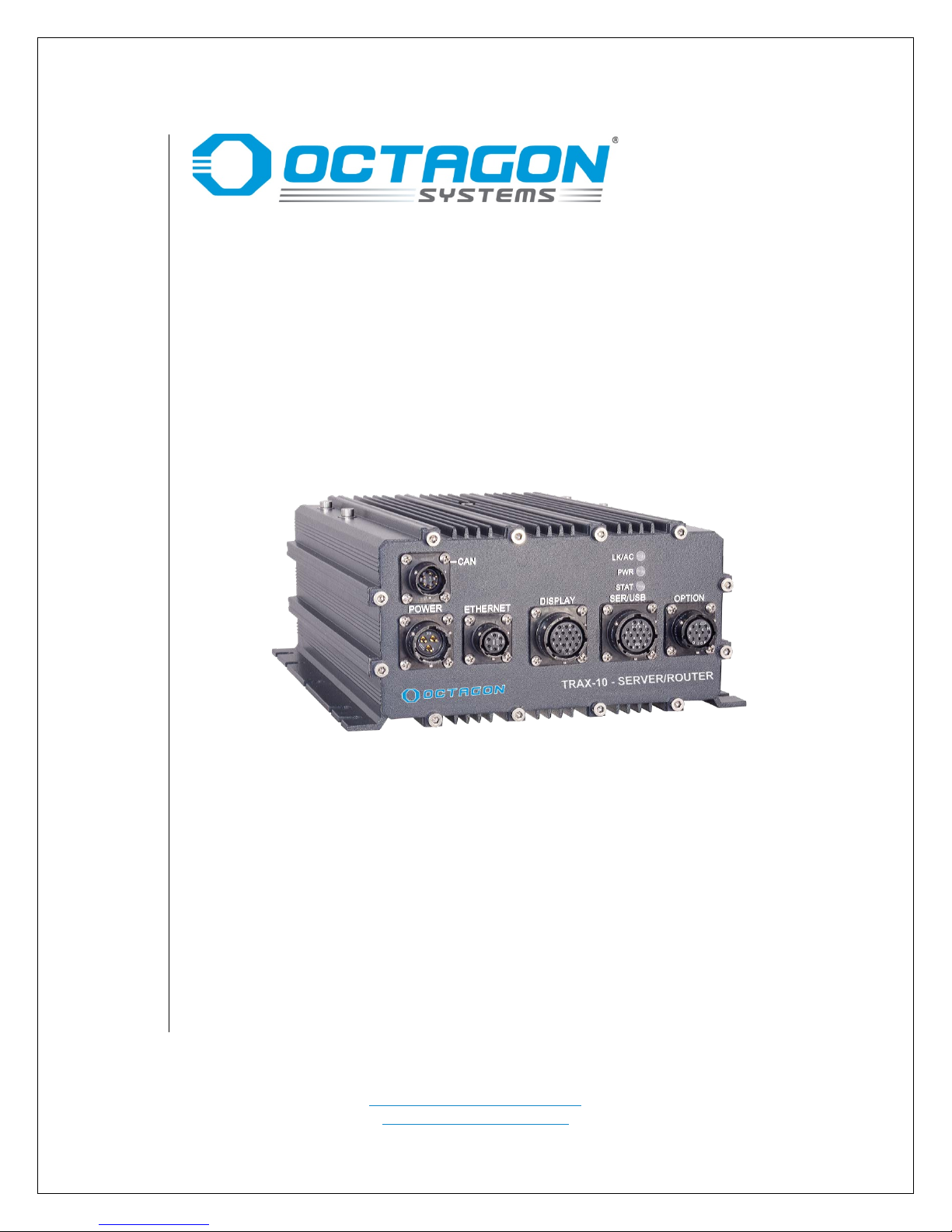
TRAX-10 Standard Model
Technical Manual
Document #9821, rev. 1.00
Superior Support – Relentless Reliability
CONTACT INFORMATION
Main Office: +1-303-430-1500
Technical Support: +1-303-426-4521
support@octagonsystems.com
www.octagonsystems.com
Octagon Systems Corporation, 7403 Church Ranch Blvd., Westminster, CO 80021-5490
Page 2

Copyright Information
Revision
Reason for Change
Date
1.00
Initial production r el e a se
09/19/17
Octagon Systems Corporation and the Octagon logo are registered trademarks of Octagon
Systems Corporation. Windows® is a registered trademark of Microsoft Corporation. Intel® is a
trademark of Intel Corporation.
Disclaimers
©2016 Octagon Systems Corporation. All rights reserved. However, small parts of this document
may be reproduced for publication or reference, provided that Octagon Systems Corporation is
cited as the source. The contents of this manual and the specifications herein may change
without notice.
The information contained in this manual is believed to be correct. However, Octagon assumes
no responsibility for any of the circuits described herein, conveys no license under any patent
or other right, and makes no representations that the circuits are free from patent
infringement. Octagon makes no representation or warranty that such applications will be
suitable for the use specified without further testing or modification.
Octagon Systems Corporation’s general policy does not recommend the use of its products in
life support applications where the failure or malfunction of a component may directly
threaten life or injury. It is a Condition of Sale that the use of Octagon products in life support
applications assumes all the risk of such use and indemnifies Octagon against all damage.
The specifications at the end of the manual are subject to change without notice. Please go to
www.octagonsystems.com to get the current specifications.
Technical Support
Carefully recheck your system before calling Technical Support. Run as many tests as possible;
the more information you can provide, the easier it will be for Technical Support staff to help
you solve the problem. For additional technical assistance, try the following:
Technical Support telephone: +1-303-426-4521
E-mail Technical Support: support@octagonsystems.com
Applications Notes (via web):
www.octagonsystems.com
Revision History
© 2016 Octagon Systems Corporation Page 2 of 17
Page 3

Table of Contents
Technical Support ................................................................................................................................... 2
Revision History ...................................................................................................................................... 2
Table of Contents ........................................................................................................................................ 3
List of Tables ............................................................................................................................................. 3
TRAX-10 Functional Overview .................................................................................................................... 4
Description ................................................................................................................................................. 4
TRAX-10 Major Hardware Features............................................................................................................ 4
Internal Functional Expansion ................................................................................................................ 4
Robust Internal Power Supply ................................................................................................................ 4
TRAX-10 major software features ............................................................................................................. 5
AMIBIOS BIOS ..................................................................................................................................... 5
Boot Sequence ........................................................................................................................................ 5
Virtualization .......................................................................................................................................... 5
Baseboard Connectors ................................................................................................................................. 8
Using the TRAX-10 ....................................................................................................................................... 9
Power ......................................................................................................................................................... 9
Ethernet ..................................................................................................................................................... 9
Audio .......................................................................................................................................................... 9
GPS ............................................................................................................................................................. 9
ANT1, ANT2 ................................................................................................................................................ 9
USB ............................................................................................................................................................. 9
Serial Communication .............................................................................................................................. 10
VGA .......................................................................................................................................................... 10
Power Management ................................................................................................................................. 10
Digital I/O ................................................................................................................................................ 11
Status LEDs ............................................................................................................................................... 11
Mating Connectors ................................................................................................................................... 12
External Connector Pin-outs ................................................................................................................. 12
Table 4 - DISPLAY Connector Pin-Out...................................................................................................... 13
Opening the TRAX-10 ................................................................................................................................ 15
Warranty .................................................................................................................................................. 16
Limitations on Warranty ....................................................................................................................... 16
Service Policy .......................................................................................................................................... 16
Returning a Product for Repair ............................................................................................................. 17
Product Return Policies ......................................................................................................................... 17
Governing Law ....................................................................................................................................... 17
List of Tables
Table 1 - Internal Connectors and Sockets ................................................................................................... 8
Table 2 – TRAX-10 Mating Connectors ........................................................................................................ 12
Table 3 - POWER Connector Pin-Out .......................................................................................................... 12
Table 4 - DISPLAY Connector Pin-Out ......................................................................................................... 13
Table 5 – ETHERNET Connector Pin-Out ..................................................................................................... 13
Table 6 – SERIAL/USB Connector Pin-Out ................................................................................................... 13
© 2016 Octagon Systems Corporation Page 3 of 17
Page 4

TRAX-10 Functional Overview
Description
The Octagon TRAX-10 incorporates an Intel®, quad-core, 64-bit X86-class computer in a
ruggedized enclosure. The high processing power couples with DirectX 11 video capability
making the TRAX-10 a mobile workstation. The unit has considerable real-world I/O, rich in
serial data pathways like Ethernet, USB, COM ports and CAN as well as wireless technologies.
Other I/O includes Concurrent GPS, high resolution video, and digital. External pow er rang e is
from 9 VDC to 36 VDC.
Internally, the TRAX-10 has a 32 GB (or larger) solid state drive, a PCI-104 interface, a Mini PCI
socket, and Mini PCI Express sockets.
TRAX-10 Major Hardware Features
The quad-core, Intel 3845 processor has a clock speed of 1.91 GHz, integral graphics and
memory controller supplied with 2 GB of DDR3 SDRAM soldered to the CPU board.
A solid state SATA Flash drive is installed for fixed disk storage. Read and write speed far
exceed the CompactFlash used in previous generation products. Densities from 32GB to 512GB
are available. Contact Octagon sales for pricing and information.
A 72- channel, concurrent, GPS receiver offers precision location and timing information. The
receiver supports 3.3V powered as well as passive antennas. The system is GPS, GLONASS,
Galileo, BeiDou QZSS and SBAS compatible.
Internal Functional Expansion
The PCI-104 interface accepts industry-standard PCI-104 boards. The Baseboard also
incorporates two Mini PCI Express slots for radios or other communication devices.
Robust Internal Power Supply
The TRAX-10 accepts a DC input voltage which can be powered from fixed supplies, vehicle
batteries or train power systems. It is protected against load dumps, reverse voltage and
transients. It was designed for 24V systems, but operates over a range of 9 to 36 VDC. The
power supply is fully isolated to minimize ground fault problems caused by multiple grounds.
© 2016 Octagon Systems Corporation Page 4 of 17
Page 5

TRAX-10 major software featu res
AMIBIOS BIOS
The TRAX-5 has an AMIBIOS BIOS optimized for the device and embedded installations.
Boot Sequence
The TRAX-10 can be configured to boot from native SATA SSD, a network resource, or from a
USB device such as a floppy drive, hard drive, flash device, or a CD–ROM. A USB or network
boot allows software installation without opening the case.
Virtualization
Hardware virtualization refers to the creation of a virtual machine that acts like a real
computer with an operating system. Software executed on these virtual machines is separated
from the underlying hardware resources. For example, a computer that is running Microsoft
Windows may host a virtual machine that looks like a computer with the Linux Mint operating
system; Linux Mint-based software can be run on the virtual machine.
---------- ♦♦♦ ----------
© 2016 Octagon Systems Corporation Page 5 of 17
Page 6

Recommended Installation Practices
The TRAX-10 is designed to operate in difficult environments. Proper installation will help ensure
product longevity and adherence to the product standards.
1. System should be connected to the vehicle frame via an earthing or grounding bolt on the
rear of the enclosure. A 14AWG (3.31mm
stud to a suitable chassis grounding point. This wire should be as short as possible. The
inclusion of an internal star washer is recommended. This provides some ground-fault
protection and reduces EMI to meet CE requirements.
2. For tracked vehicles, shock mounting would be prudent.
3. Opening the unit must not be done in the field, but at an approved antistatic workstation.
The unit may be opened to replace/install wireless and/or SIM cards. Instructions for
opening the case are available from Octagon Technical Support.
4. The unit should be mounted so as to not impede the convection cooling. Vertical mount is
preferable. It is strongly recommended that the space between the heat fins and other
objects exceed 100 mm (4”) and there is at least 50 mm (2”) of open space on the other
sides. Avoid “dead air” spaces such as under seats. The unit should not be bolted to any
surface that is hotter than the ambient air surrounding the unit.
5. The protective caps must be left on all unused connectors. Failure to do so may render
those connectors unusable in the future due to corrosive liquids or conductive dust.
6. There are no internal repairable components. Customer field repair is in violation of
Octagon’s warranty.
2) stranded wire should be used to connect this
7. Do not over-tighten the antenna cable connectors.
8. The TRAX-10 includes mounting flanges that must be secured to a surface with ¼ inch or 6
mm bolts or screws.
9. The power supply cable gauge should be as large and as short in as practicable.
10. The TRAX-10 is protected against transient voltages common in mobile applications. It is
recommended that external in-lin e fuses be us ed on bo th in put po wer lin es . Oc t ag o n
recommends standard, fast acting 10A fuses.
11. Proper ESD precautions and method must be followed when installing, servicing, or
otherwise handling the TRAX-10.
12. The USB 2.0 has a maximum cable length of 5M. Cables with built-in repeaters to extend
this length should not be used.
13. The TRAX-10 contains several switching regulators with an inrush requirement of 10A. The
external supply must be capable of supplying this inrush current so as to not “starve” the
startup of the internal supplies. If the power supply is mounted remotely to the TRAX-10,
the wiring size must be increased to prevent excessive drop during startup.
14. Contact Octagon Technical Support for proper disassembly/ access to internal options &
expansion. Storage options must be factory installed.
15. To power down the TRAX-10, turn the ignition switch off. Allow two minutes for the
automatic shut-down sequence (saving data and configuration) to complete. The LED on
the display will go off signaling the completion.
16. High pressure, power washing is prohibited
Warning – During Arc w elding/Electrical Resis tance welding on the vehicle i n which
this product is installed, EVERY and ALL cables to the unit must be disconnected
prior to welding. Otherwise the unit may be s eriously damaged and the warranty is
VOID.
© 2016 Octagon Systems Corporation Page 6 of 17
Page 7
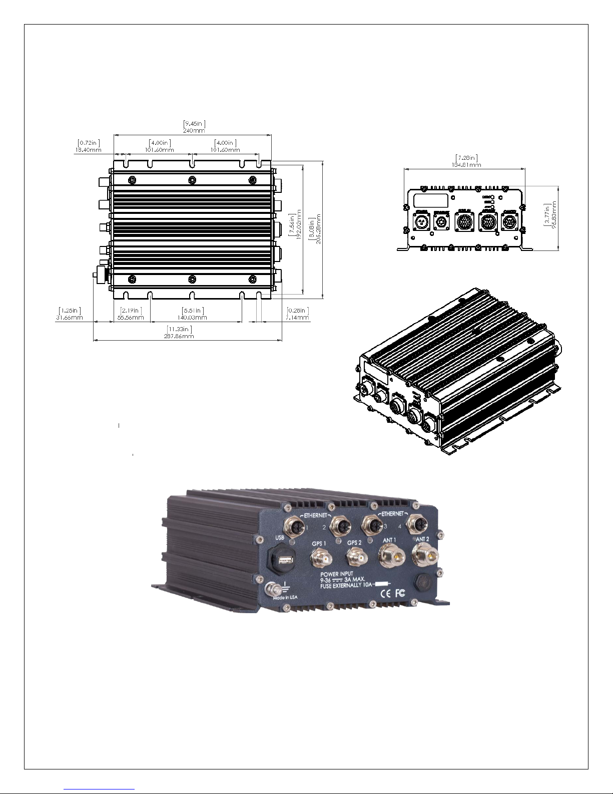
TRAX-5, 10 Case Dimensions [inches] mm
Back panel shown without options
© 2016 Octagon Systems Corporation Page 7 of 17
Page 8

Baseboard Connectors
J11-
PCI/104
J11
PCI / 104 Connector
J8
SIM card socket for J4
J16
SATA connector
J9
SIM card socket for J5
XU1
Mini PCI socket
J2
To power supply
Table 1 - Internal Connectors and Sockets
© 2016 Octagon Systems Corporation Page 8 of 17
---------------------------------
Page 9

Using the TRAX-10
Power
The TRAX-10 is rated for nominal 24V battery operation, but accepts 9V to 36V. The low end
rating is for starting the vehicle. Sustained operation below 10V is not recommended. The
external power cable negative and positive battery leads must be at least 16 AWG and should
be stranded wire. The Ignition signal controls the power management Suspend and Resume
functions; this signal should be connected to the vehicle ignition, or tied to +Battery, if
unused. The wire may be 18AWG (~0.823 mm
NOTE: Reversing the battery leads will not damage the unit. It will not function and there is no
indicator for reverse polarity.
CAUTION: It is mandatory that the low resistance, electrical connection be made between
the earthing or grounding bolt on the rear of the unit and the vehicle frame. This will
insure that the CE and UL limits with regards to radiation emission are met, as well as
safety considerations.
Ethernet
The TRAX-10 provides one 100Base-T Ethernet and four 10/100/1000Base-T Ethernet ports.
These ports support the IEEE 802.3 Ethernet standard. Note that you must have the correct
Ethernet driver installed to be able to use the Ethernet port. The Ethernet driv er is available
on the Octagon Systems web site.
2
).
Audio
The TRAX-10 provides a monaural line output, included in the display connector. The default
configuration is a line level (1V P-P) output.
GPS
The rear panel contains two TNC type GPS connectors. The high performance GPS receiver is a
standard feature of the TRAX-10 system. The GPS is connected to the CPU through an internal
USB interface. The receiver supports industry standard NMEA messages, as well as the UBX
packet protocol
ANT1, ANT2
There are two type “N” antenna connectors on the rear panel that provide connection to
optional internal wireless communication modules. Numerous communication formats are
implemented with add-on cards such as Mini PCI Express and Mini PCI. An internal cable
connects the card to the appropriate external connector.
USB
The TRAX-10 provides two USB 2.0 ports on the front panel- one in the Display connector, and
one in the Serial/USB connector. The system is capable of booting from external USB storage
devices and CD/DVD drives.
© 2016 Octagon Systems Corporation Page 9 of 17
Page 10

Serial Communication
The TRAX-10 has four serial ports. One port supports RxD, TxD, RTS and CTS. Two of the ports
implement RxD and TxD. The fourth port supports RxD/TxD, RS-232 and RS-485
RS 485 operation flow chart
Be aware that operating systems may assign port numbers in a different order, such as 1, 2,
and 3. Identification of the hardware ports can be done by checking the address of the I/O
resource associated with each COM port by the OS.
VGA
The VIDEO connector has standard VGA signals. Display resolution up to 1920x1200 is
supported.
Power Management
The TRAX-10 system hardware and BIOS support ACPI power management functions.
The Ignition Detect signal on the Power connector controls the power management Power on
and Shutdown functions; this signal should be connected to the vehicle ignition. If not used,
the Ignition Detect signal must be tied to +Battery to allow the system to start.
Operation when the ignition terminal is connected to vehicle ignition, or a “switched” power
source is as follows: The system will remain in “soft off” – a very low power state as long as
Ignition remains low. When Ignition is raised to +Battery level, system startup is initiated,
after a short delay to ensure Power and Ignition are stable. Disconnecting Ignition, or
connecting to ground will signal the operating system to shut down – however the system
remains on, drawing power from the +Battery terminal until shutdown occurs and the system
returns to soft off. Failure of the operating system to shut down in a reasonable time will
result in a forced soft off state.
Shutting down the operating system while ignition is connected to power levels (high state) will
cause the system to shut dow n and re -start. In order to shut the system off, the ignition switch
must be opened.
© 2016 Octagon Systems Corporation Page 10 of 17
Page 11

Digital I/O
The TRAX-10 provides one digital output. When activated, it provides a ground for external
devices connected to the vehicle voltage. When inactive it appears as an open. The line can
withstand voltages up to 100V when in the off state and can sink 100 mA when active.
The output line will provide 1A peak repetitive for 50mS for driving incandescent lamps
switching on at a rate of one per second, at a 50% duty cycle with a 50mA lamp. The output
line has inductive load protection with a 1A, 100V diode across the load, and the cathode
connected to the supply voltage.
The TRAX-10 also provides five digital inputs. The inputs detect a positive voltage with an
input range of 0V to +Battery. The input is inactive when open (less than 100mA) and active
when connected to a positive voltage of 4-36VDC.
Note that drivers written by Octagon indicate a binary value of 0 when the input is
open/inactive, and 1 when active.
The TRAX10 uses a (SATA) solid state storage device to act as the system hard disk drive.
Storage options are available from 32 GB to 512 GB. All storage options must be factory
installed.
Storage
Status LEDs
The TRAX-10 has 3 front panel status LEDs:
LAN indicates LAN link (green) and activity (yellow).
STAT is a user controlled bi-color status LED. Accessing the LED registers is
accomplished through operating system drivers. Contact Octagon for driver
availability and/or a Board Support Package for your Operating System.
PWR is a Power indicator, indicating On (Green) or Standby (Yellow) state of the
power supply.
The TRAX 10 has 4 rear panel Ethernet status LEDs, one for each Ethernet po rt. Each bi-color
LED indicates:
GREEN ON /GREEN BLINKING = 100Mb operation + Activity
GREEN BLINKING / YELLOW ON = 1Gb operation + Activity
---------- ♦♦♦ ----------
© 2016 Octagon Systems Corporation Page 11 of 17
Page 12

External Connectors
Connector
Function
Mating Connector
GPS
GPS antenna
TNC-F, 50
ANT1
Wireless Accessory ( optional)
N-F, 50
Cellular
Wireless WAN (option al )
N-F, 50
Power
Power Input
PT06E12-3SSR or similar
Ethernet
LAN
PT06E10-6PSR or similar
Serial/USB
COM ports, USB
PT06E14-18PSR or similar
Option
Digital I/O & Option
PT06E12-10PSR or similar
Dual CAN Bus
CAN Bus
PT06E10-6SSR or similar
Signal Name
Pin #
V_IN (Voltage IN)
A
GND_EXT (Ext Gnd)
B
Mating Connector PT06E12-3SSR
Table 2 – TRAX-10 Mating Connectors
Display Video, Audio, USB PT06E14-19PSR or similar
Ethernet (rear) Gb Ethernet x 4 M12-x coded
Mating Connectors
External Connector Pin-outs
The following descriptions are as seen from the outside of the faceplate.
Table 3 - POWER Connector Pin-Out
PT02E1203P
IGNITION C
The external power cable must be at least 16AWG for cables of 2M or shorter. For
longer cables, use 14AWG. The Ignition Det ect sig nal controls the power management
Suspend and Resume functions; this signal should be connected to the vehicle ignition.
This wire may be as small as 18AWG.
© 2016 Octagon Systems Corporation Page 12 of 17
Page 13

Table 4 - DISPLAY Connector Pin-Out
L
A
D
R
S
H
G
P
U
T J
B
N
M
K
C
E
F
V
14-19S
Signal Name
Pin #
Pin #
Signal Name
Display Power ―
A L BLUE shield
Display Power +
B M H Sync
VGA-SCL
C N VGA-SDA
Audio LINE out
D P V Sync
GND Audio
E R GND USB0
RED
F S USB0 +5V
GREEN shield
J V USB0 Shield
BLUE
K
Mating Connector PT06E14-19PSR
Signal Name
Pin #
Pin #
Signal Name
A
B
C
10-
6S
F
E
D
LAN Rx-
B E LAN Tx+
Mating Connector PT06E10-6PSR
Signal Name
Pin #
Pin #
Signal Name
PT02E1418S
14-18S
L
A
D
R
S
H
G
P
UT
J
B
N
M
K
C
E
F
COM3 TXD
A K COM1 GND
COM3 RXD
B L COM1 TXD
USB1 Data+
E P COM2 RXD
USB1 Data-
F R COM2 GND
USB1 GND
G S COM4 D-/TXD
COM1 CTS
H T COM4 D+/RXD
COM1 RTS
J U COM4 GND
Mating Connector PT06E14-18PSR
Signal Name Pin # Pin # Signal Name PT02E1419S
(rear view)
RED shield G T USB0 D ―
GREEN H U USB0 D +
Table 5 – ETHERNET Connector Pin-Out (Front Panel)
PT02E106S
LAN Rx+ A D LAN Tx-
Shield ground C F Reserved
Table 6 – SERIAL/USB Connector Pin-Out
COM3 GND C M COM1 RXD
USB1 +5V D N COM2 TXD
© 2016 Octagon Systems Corporation Page 13 of 17
(rear view)
Page 14

Table 7 – OPTION Pin-Out
Signal Name
Pin #
Pin #
Signal Name
A
D
H
G
JBK
C
E
F
12
-
10S
Option
A F Digital IN 1
Digital Out 0
D J Digital IN 3
A
B
C
10
-6
S
F
E
D
B
E
Mating Connector PT06E10-6SSR
Pin #
Signal
1
MDX0+
2
MDX0-
3
MDX1+
4
MDX1-
5
MDX3+
6
MDX3-
7
MDX2-
8
MDx2+
PT02E1210SW
(rear view)
Option B G Digital IN 0
Option C H Dig common
Digital IN 2
Digital IN 4 E K
Mating Connector PT06E12-10PSR
Table 8 – DUAL CAN Pin-Out (CAN1 is an option)
Signal Name Pin # Pin # Signal Name PT02E106P
CAN0 L
CAN0 GND
A D
CAN1 L
CAN1 GND
CAN0 H C F CAN1 H
Table 9 – ETHERNET Connector Pin-Out - rear pan el
---------- ♦♦♦ ----------
© 2016 Octagon Systems Corporation Page 14 of 17
Page 15

Opening the TRAX-10
This is not recommended. Access to the SIM card and wireless module sockets requires the
enclosure be opened. This must be done in accordance with safe and approved methods in an
approved anti-static environment. Larger storage devices can only be installed as factory
options. Contact Octagon Technical Support for complete instructions prior to disassembling
the unit. Failure to properly reassemble the environmental protection (gaskets) will void the
warranty.
---------- ♦♦♦ ----------
© 2016 Octagon Systems Corporation Page 15 of 17
Page 16

Warning – If Arc welding or Electrical Resistance welding is being done on the
vehicle in which this product is installed, EVERY and ALL cables to the unit must
be disconnected prior to welding.
Otherwise the unit may be seriously damaged and the warranty is VOID.
Warranty
Octagon Systems Corporation (Octagon) warrants that its standard hardware products will
be free from defects in materials and workmanship under normal use and service for the
current established warranty period. Octagon’s obligation under this warranty shall not arise
until Buyer returns the defective product, freight prepaid to Octagon’s facility or another
specified location. Octagon’s only responsibility under this warranty is, at its option, to
replace or repair, free of charge, any defective component part of such products.
Limitations on Warranty
The warranty set forth above does not extend to and shall not apply to:
1. Products, including software, which have been repaired or altered by other than
Octagon personnel, unless Buyer has properly altered or repaired the products in
accordance with procedures previously approved in writing by Octagon.
2. Products which have been subject to power supply reversal, misuse, neglect,
accident, or improper installation.
3. The design, capability, capacity, or suitability for use of the Software. Software is
licensed on an “AS IS” basis without warranty.
The warranty and remedies set forth above are in lieu of all other warranties expressed or
implied, oral or written, either in fact or by operation of law, statutory or otherwise,
including warranties of merchantability and fitness for a particular purpose, which Octagon
specifically disclaims. Octagon neither assumes nor authorizes any other liability in
connection with the sale, installation or use of its products. Octagon shall have no liability
for incidental or consequential damages of any kind arising out of the sale, delay in delivery,
installation, or use of its products.
Service Policy
1. If a product should fail during the warranty period, it will be repaired free of
charge. For out-of-warranty repairs, the customer will be invoiced for repair
charges at current standard labor and materials rates.
2. If a product returned for repairs is found to be free of defect, customer may be liable
for the minimum current repair charge.
© 2016 Octagon Systems Corporation Page 16 of 17
Page 17

Returning a Product for Repair
1. The customer must call Tech Support at 1–303-426-4521 to determine if the problem
can be resolved without a return.
2. If repair service is required, Tech Support will require the customer’s name, address,
telephone number, email address and a list of problems found.
3. Tech Support will forward this information to the RMA Administrator who will
contact the customer to issue the RMA number.
4. The customer must carefully package the product in an antistatic container. Failure
to package in antistatic packaging will VOID all warranties. Then package in a safe
container for shipping.
5. Write the RMA number on the outside of the shipping container.
6. The customer pays for shipping to Octagon. Octagon pays for shipping back to the
customer. Expedited shipping may incur costs to the customer.
7. Other conditions and limitations may apply to international shipments.
Note PRODUCTS RETURNED TO OCTAGON FREIGHT COLLECT OR WITHOUT AN RMA
NUMBER CANNOT BE ACCEPTED AND WILL BE RETURNED FREIGHT COLLECT.
Product Return Policies
Custom and semi-custom orders are non-cancelable and the product is non-returnable unless
otherwise provided by contract.
Standard products may, at Octagon’s option, be returned according to the standard
restocking policy at the time of return.
Governing Law
This agreement is made in, governed by and shall be construed in accordance with the laws
of the State of Colorado.
The information in this manual is provided for reference only. Octagon does not assume any
liability arising out of the application or use of the information or products described in this
manual. This manual may contain or reference information and products protected by
copyrights or patents. No license is conveyed under the rights of Octagon or others.
---------- ♦♦♦ ----------
© 2016 Octagon Systems Corporation Page 17 of 17
 Loading...