

Page 1
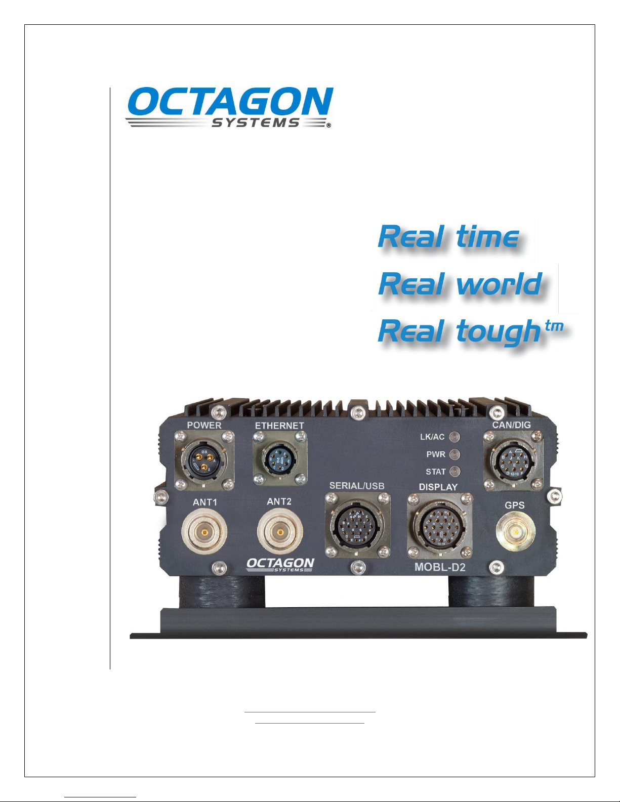
MOBL-D2
Technical Manual
Document #9186, rev. B12
Octagon Systems Corporation, 7403 Church Ranch Blvd., Westminster, CO 80021-5490
CONTACT INFORMATION
Front Desk: 1–303–430–1500
Technical Support: 1–303–426–4521
FastHelp@octagonsystems.com
www.octagonsystems.com
A Colorado Corporation
Page 2
Revision
Reason for Change
Date
A12
Initial production release
April 2012
B12
Notes regarding shock
isolators added.
April 2012
Copyright Information
Octagon Systems®, and the Octagon logo are registered trademarks of Octagon Systems
Corporation. “Real time Real world Real tough™" is a trademark of Octagon Systems
Corporation. Windows XP® is a registered trademark of Microsoft Corporation.
HyperTerminal™ is a copyright of Hilgraeve, Inc. CompactFlash™ is a trademark of San
Disk Corporation. Ethernet® is a registered trademark of Xerox Corporation. Pentium® is a
registered trademark of Intel.
Disclaimers
©2012 Octagon Systems Corporation. All rights reserved. However, small parts of this
document may be reproduced for publication or reference, provided that Octagon Systems
Corporation is cited as the source. The contents of this manual and the specifications herein
may change without notice.
The information contained in this manual is believed to be correct. However, Octagon
assumes no responsibility for any of the circuits described herein, conveys no license under
any patent or other right, and makes no representations that the circuits are free from
patent infringement. Octagon makes no representation or warranty that such applications
will be suitable for the use specified without further testing or modification.
Octagon Systems Corporation’s general policy does not recommend the use of its products in
life support applications where the failure or malfunction of a component may directly
threaten life or injury. It is a Condition of Sale that the user of Octagon products in life
support applications assumes all the risk of such use and indemnifies Octagon against all
damage.
Technical Support
Carefully recheck your system before calling Technical Support. Run as many tests as
possible; the more information you can provide, the easier it will be for Technical Support
staff to help you solve the problem. For additional technical assistance, try the following:
Technical Support telephone: 303–426–4521
E-mail Technical Support: fasthelp@octagonsystems.com
Applications Notes (via web): www.octagonsystems.com
Revision History
www.octagonsystems.com Page 2 of 22
Page 3

Table of Contents
Technical Support ................................................................................................................................. 2
Revision History .................................................................................................................................... 2
Table of Contents ..................................................................................................................................... 3
List of Figures ........................................................................................................................................... 4
List of Tables ............................................................................................................................................. 4
MOBL-D2 Functional Overview ........................................................................................................... 5
Description ................................................................................................................................................ 5
MOBL-D2 major hardware features ....................................................................................................... 5
Internal Functional Expansion ............................................................................................................ 5
Robust Internal Power Supply ............................................................................................................. 5
MOBL-D2 major software features ......................................................................................................... 6
AMIBIOS BIOS ..................................................................................................................................... 6
Boot sequence ........................................................................................................................................ 6
Configuring and Ordering Your System ............................................................................................ 6
Hard Drive Options .................................................................................................................................. 6
Expansion Options ................................................................................................................................... 6
Operating Systems ................................................................................................................................... 6
Installation ................................................................................................................................................ 7
Recommended Installation Practices ...................................................................................................... 7
Using the MOBL-D2 ............................................................................................................................... 10
Power ....................................................................................................................................................... 10
Ethernet .................................................................................................................................................. 10
Audio ....................................................................................................................................................... 10
GPS .......................................................................................................................................................... 10
ANT1, ANT2 ........................................................................................................................................... 10
USB ......................................................................................................................................................... 10
Serial communication............................................................................................................................. 10
VGA ......................................................................................................................................................... 11
Power Management ................................................................................................................................ 11
Digital I/O ............................................................................................................................................... 11
Status LEDs ............................................................................................................................................ 12
Technical specifications ....................................................................................................................... 13
CPU, FSB and SDRAM....................................................................................................................... 13
BIOS ..................................................................................................................................................... 13
On-board flash ..................................................................................................................................... 13
Hard drive ............................................................................................................................................ 13
USB ...................................................................................................................................................... 13
Serial I/O .............................................................................................................................................. 13
Digital I/O ............................................................................................................................................ 13
Ethernet ............................................................................................................................................... 13
Real time clock .................................................................................................................................... 14
Keyboard and mouse ports ................................................................................................................. 14
Video .................................................................................................................................................... 14
Expansion ............................................................................................................................................ 14
Operating systems .............................................................................................................................. 14
Power input ......................................................................................................................................... 14
Environmental specifications ............................................................................................................. 14
Antenna Connectors ............................................................................................................................ 14
Size and Weight................................................................................................................................... 14
www.octagonsystems.com Page 3 of 22
Page 4

Mating connectors .................................................................................................................................. 15
External connector pin-outs ................................................................................................................... 15
Software and Hardware Development ............................................................................................. 17
Opening and closing the MOBL-D2 box ................................................................................................ 17
Component locations .............................................................................................................................. 18
USB ......................................................................................................................................................... 19
Mini PCI .................................................................................................................................................. 19
Mini PCI Express ................................................................................................................................... 19
PCI-104 ................................................................................................................................................... 19
Accessories ............................................................................................................................................... 20
Warranty .................................................................................................................................................. 21
Limitations on warranty ........................................................................................................................ 21
Service policy .......................................................................................................................................... 21
Returning a product for repair .............................................................................................................. 21
Product return Policies .......................................................................................................................... 22
Governing law ......................................................................................................................................... 22
List of Figures
Figure 1 - Mounting hole and system dimensions [inches] mm ............................................................... 8
Figure 2 – MOBL-D2 case dimensions [inches] mm ................................................................................. 9
Figure 3 - Internal Connectors and Sockets ............................................................................................ 18
List of Tables
Table 1 – MOBL-D2 Mating Connectors .................................................................................................. 15
Table 2 - Power Connector Pin-Out .......................................................................................................... 15
Table 3 - Display Connector Pin-Out ....................................................................................................... 16
Table 4 – Ethernet Connector Pin-Out .................................................................................................... 16
Table 5 – Serial/USB Connector Pin-Out ................................................................................................. 16
Table 6 - Internal Connectors and Sockets .............................................................................................. 19
Table 10 - PCI-104signal deviations ......................................................................................................... 20
Table 11 - Accessories ................................................................................................................................ 20
www.octagonsystems.com Page 4 of 22
Page 5

MOBL-D2 Functional Overview
Description
The Octagon MOBL-D2 is a 32-bit X86-class computer in a ruggedized enclosure. The
connectors and interfaces are located on an external panel for easy access.
The MOBL-D2 provides the following external interfaces: GPS, Wireless LAN (optional),
Wireless WAN (optional), and Bluetooth; each with front panel antenna connections. A
rugged Display connection is provided with audio output and a USB connection for devices
such as touch-screen controllers. Similar rugged connectors are also provided for
Communications (Serial & USB), Ethernet, and Digital I/O & CAN Bus as well as external
power. External power can range from 9 VDC to 36 VDC.
Internally the MOBL-D2 has a Compact Flash socket, a PCI-104interface, a Mini PCI socket
(Wireless LAN), and a Mini PCI Express socket (Wireless WAN). The MOBL-D2 can be used
in a stand-alone mode or expanded through the PCI-104, Mini PCI, or Mini PCI Express
interfaces.
MOBL-D2 major hardware features
The Vortex86MX processor has a clock speed of 800 MHz, integral graphics and memory
controller supplied with 1 GB of DDR2 SDRAM soldered to the CPU board.
An optional Compact Flash drive if ordered with the system is installed for fixed disk
storage.
A Fifty Channel GPS receiver offers location and timing information. The receiver supports
3.3V powered as well as passive antennas.
A Bluetooth interface is standard on the MOBL-D2, and is provided with an external
antenna connected to the front panel.
A rear panel USB port with tethered cover is provided for maintenance, diagnostics, updates,
or other temporary use without the need to disconnect front-panel dedicated cables to access
a USB port.
The case of the MOBL-D2 is integrally coupled to the major heat producing components,
which significantly reduces internal heating. No cooling fan is required.
Internal Functional Expansion
The PCI-104interface accepts industry-standard PCI-104boards. PCI-104expansion boards
are available from several manufacturers. The CPU card also incorporates a Mini PCI and a
Mini PCI Express slot for radios or other communication devices. The Mini PCI Express slot
supports only USB interface devices such as Wireless WAN cards, no PCI Express bus is
presented to the socket.
Robust Internal Power Supply
The MOBL-D2 accepts a DC input voltage which can be powered from fixed supplies, vehicle
batteries or train power systems. The internal power supply has a very robust front end,
exceeding the SAE J1113-11 and ISO 7637-2 specifications. It is also reverse polarity
protected. The input range is from 9 to 36 VDC.
www.octagonsystems.com Page 5 of 22
Page 6

MOBL-D2 major software features
AMIBIOS BIOS
The MOBL-D2 has an AMIBIOS BIOS optimized for the device and embedded installations.
Boot sequence
The MOBL-D2 can be configured to boot from Compact Flash, a network resource, or from a
USB device such as a floppy drive, hard drive, flash device, or a CD–ROM. A USB or network
boot allows software installation without opening the case.
Configuring and Ordering Your System
Hard Drive Options
The MOBL-D2 uses an optional Compact Flash device or external USB drive(s).
The internal Compact Flash socket looks like a hard drive to the system. This socket accepts
Type I or Type II Compact Flash devices. The Compact Flash feature is CF 3.0 compliant,
DMA capable, and supports true IDE mode. Octagon Systems only recommends industrial
grade, error-correcting Compact Flash of the quality available with the system.
Expansion Options
The MOBL-D2 can be used in a stand-alone mode or expanded through the Mini PCI, Mini
PCI Express (USB functions only) and PCI-104interfaces. Up to two PCI-104cards can be
added.
Operating Systems
Octagon Systems can preinstall some operating systems, including drivers for the standard
features such as digital I/O and COM ports. Octagon Systems has drivers for Windows XPe
and Linux for the standard MOBL-D2 features, as well as for Octagon System expansion
cards.
www.octagonsystems.com Page 6 of 22
Page 7
Installation
Recommended Installation Practices
CAUTION!
When replacing the back cover ensure the threads on the bolts are
properly aligned before tightening. Do not over tighten. Torque to 1.1 NM (10 in-lbs.) Failure to follow these precautions could strip the internal
threads.
The MOBL-D2 is designed to operate in difficult environments. Proper installation
will help ensure product longevity and adherence to the product standards.
1. The back endplate of the MOBL-D2 can be removed for access to the Compact
Flash. The bolts require a 4 mm hex wrench.
2. There are no internal repairable components. Field repair is not covered by
the Octagon warranty.
3. Do not over-tighten the antenna or GPS connectors.
4. The MOBL-D2 includes a standard vibration and shock dampening mounting
plate. The mounting plate must be secured to a surface with four bolts or
screws
5. The power supply cable should be as large a gauge and as short in length as
practicable.
6. The MOBL-D2 is protected against transient voltages common in mobile
applications. It is required that an external in-line fuse be used if a remote
power supply is used. This will prevent catastrophic damage from power
supply reversal and sustained over-voltage. A fast-actingfuse at 5A must be
used.
7. Proper ESD precautions and method must be followed when installing,
servicing, or otherwise handling the MOBL-D2.
8. The USB signals are USB 2.0 with a maximum cable length of 5M. Cables
with built-in repeaters are available commercially if a longer cable length is
required.
9. The MOBL-D2 is rated for 12V to 24V nominal, but accepts 9V to 36V.
10. The MOBL-D2 contains several switching regulators with an inrush
requirement of 10A. The external supply must be capable of supplying this
inrush current so as to not “starve” the startup of the internal supplies. If the
power supply is mounted remotely to the MOBL-D2, the wiring gauge must
be adjusted to prevent excessive drop during startup.
11. Contact Octagon Systems Technical Support for proper disassembly / access
to internal options & expansion.
www.octagonsystems.com Page 7 of 22
Page 8

CAUTION!
Do NOT remove, loosen, or tighten the screws attaching shock
isolators to the mounting plat shown above. Accidental damage
to the shock isolators may result. Refer any damaged mounting
system to qualified repair personnel.
Figure 1 - Mounting hole and system dimensions [inches] mm
www.octagonsystems.com Page 8 of 22
Page 9

CAUTION!
Do NOT attempt to separate case from mounting plate.
Accidental damage to the shock isolators may result. Refer any
damaged mounting system to qualified repair personnel.
Figure 2 – MOBL-D2 case dimensions [inches] mm
www.octagonsystems.com Page 9 of 22
Page 10

Using the MOBL-D2
Power
The MOBL-D2 is rated for 12V to 24V nominal, but accepts 9V to 36V. The external power
cable must be at least 18 gauge. The Ignition Detect signal controls the power management
Suspend and Resume functions; this signal should be connected to the vehicle ignition, or
tied to VIN if unused.
Ethernet
The MOBL-D2 provides one 10/100Base-T Ethernet port. The port supports the IEEE 802.3
Ethernet standard. The Ethernet ports use PCI interrupts as assigned by the operating
system. Note that you must have the correct Ethernet driver installed to be able to use the
Ethernet port. The Ethernet driver is available on the Octagon Systems web site.
Audio
The MOBL-D2 provides a monaural line output, included in the display connector. The
default configuration is a line level (1V P-P) output.
GPS
The front panel contains a TNC GPS connector. The GPS receiver is a standard feature of
the MOBL-D2 system. The GPS is connected to the CPU through an internal USB interface.
The receiver supports industry standard NMEA messages, as well as the UBX packet
protocol. The protocol specifications are available from the Octagon Systems website.
ANT1, ANT2
There are 2 N antenna connectors provided for optional wireless communication modules.
Numerous communication formats are implemented with add-on card such as PCI-104, Mini
PCI. An internal cable connects the card to the appropriate external connector.
USB
The MOBL-D2 provides two USB 2.0 ports on the front panel- one in the Display connector,
and one in the Serial/USB connector. Additionally there is a third USB connector provided on
the rear panel of the MOBL-D2. This port includes a tethered cover or cap which must be
securely placed over the connector when not in use. This rear USB connector is NOT
DESIGNED FOR DEDICATED CONNECTION WHEN INSTALLED, but intended for
service, maintenance, or diagnostic functions. Peripherals can be connected and
disconnected while power is applied to the system. The system is capable of booting from
external USB storage devices and CD/DVD drives. NOTE: The MOBL-D2 cannot boot from
USB devices connected to the rear USB port.
Serial communication
The MOBL-D2 has three serial ports. COM1 and COM4 are 2-wire (plus ground) RS–232
interfaces. COM2 is not installed. COM 3 is a 2 wire RS–485 interface.
Note: COM port numbers used in this manual refer to the standard I/O base address
assignments as follow: COM1 = 0x3F8, COM3 = 0x3E8, COM4 = 0x2E8. COM2 is not used
in the MOBL-D2 hardware. Be aware that operating systems may assign port
www.octagonsystems.com Page 10 of 22
Page 11

numbers in a different order, such as 1, 2, and 3. Identification of the hardware ports can
be done by checking the address of the I/O resource associated with each COM port by the
OS.
VGA
The VIDEO connector has standard VGA signals. Display resolution up to 1280x1024 is
supported.
Power Management
The MOBL-D2 system hardware and BIOS support APM power management functions.
The Ignition Detect signal on the Power connector controls the power management Power on
and Shutdown functions; this signal should be connected to the vehicle ignition. If not used,
the Ignition Detect signal must be tied to VIN to allow the system to start.
Operation when the ignition terminal is connected to vehicle ignition, or a “switched” power
source is as follows: The system will remain in “soft off” – a very low power state as long as
Ignition remains low. When Ignition is raised to VIN system startup is initiated, after a
short delay to ensure Power and Ignition are stable*. Disconnecting Ignition, or connecting
to ground will signal the operating system to shut down – however the system remains on,
drawing power from the VIN terminal until shutdown occurs and the system returns to soft
off. Failure of the operating system to shutdown in a reasonable time* will result in a forced
soft off state.
Shutting down the operating system while ignition is connected to power levels (high state)
will cause the system to enter a standby low power state indicated by a yellow power LED on
the front panel, and will remain as long as ignition is applied. Removal and reapplication of
voltage to the ignition lead will restart the system.
If ignition should be removed long enough to initiate shutdown, but returns before shutdown
of the operating system is complete, the system will automatically restart.
*The Ignition Minimum Time and Force Off Timeout are programmable with a configuration
utility available from Octagon Systems (contact tech support), however are initially set to 3
seconds and 180 seconds respectively by the factory.
Digital I/O
The MOBL-D2 provides one digital output. When activated, provides a ground for external
devices connected to the vehicle voltage. When inactive it appears as an open. The line can
withstand voltages up to 100V when in the off state and can sink 100 mA when active.
The output line will provide 1A peak repetitive for 50mS for driving incandescent lamps
switching on at a rate of one per second, at a 50% duty cycle with a 50mA lamp. The output
line has inductive load protection with a 1A, 100V diode.
The MOBL-D2 also provides four digital inputs. The inputs detect connection (current sink)
to ground. The input is inactive when open (less than 100µA), and active when connected to
ground (sinking at least 1mA). The digital lines are limited 10ma external current sink.
Note that drivers written by Octagon Systems indicate a binary value of 1 when the input is
open/inactive, and 0 when grounded.
www.octagonsystems.com Page 11 of 22
Page 12

Status LEDs
The MOBL-D2 has 3 status LEDs:
LAN indicates LAN link (green) and activity (yellow).
STAT is a user controlled bi-color status LED. Accessing the LED registers is
accomplished through operating system drivers. Contact Octagon Systems for
driver availability and/or a Board Support Package for your Operating System.
PWR is a Power indicator, indicating On (Green) or Standby (Yellow) state of the
power supply.
www.octagonsystems.com Page 12 of 22
Page 13

Technical specifications
CPU, FSB and SDRAM
The DM&P Vortex86MX processor has a clock speed of 800MHz and is equipped with 1 GB of
DDR2 SDRAM.
BIOS
AMIBIOS
On-board flash
512 KB flash, contains system BIOS.
Hard drive
The MOBL-D2 accepts a Compact Flash drive, on the primary IDE channel. The Compact
Flash socket accepts industrial Type I or Type II compact flash devices. The MOBL-D2 may
also be expanded with external USB drives.
USB
Two external ports are available from the front panel, and one diagnostic/service port on the
rear panel. All ports are USB 2.0 compliant.
Serial I/O
Two dedicated 2-wire RS–232 interfaces, one dedicated 2-wire RS–485 interfaces.
IEC1000, level 3, ESD protection specification
— Contact discharge ±6 kV
— Air–gap discharge ±8 kV
Up to 115.2K baud
Digital I/O
One digital output, 100ma current sink.
Four ground detecting digital inputs – external current limit / resistor not required.
Ethernet
One 10/100Base-T port, supporting IEEE 802.3.
www.octagonsystems.com Page 13 of 22
Page 14

Real time clock
AT compatible with battery backup.
Keyboard and mouse ports
Supports USB keyboard and mouse.
Video
The MOBL-D2 supports VGA display up to 1280x1024 pixel resolution.
Expansion
PCI-104, up to 2 cards.
Mini PCI, one slot.
Mini PCI Express (aka PCI Express Mini-Card) slot supporting only USB functions, one slot.
Operating systems
Driver support for Windows XPe and Linux. Optional pre-installed Linux or XPe available.
Power input
9 - 36 VDC input. 7W typical, exclusive of expansion.
Environmental specifications
Operating temperature –30° to +70°C
Non-operating temperature –55° to 95°C, nonoperating
Relative humidity 5% to 95% noncondensing
Shock 20g, 3 axis per MIL-STD 810F, Test Method
516.5, Functional shock test (4.5.2) 20g peak
Vibration Per MIL-STD 810F, Test Method 514.5, Annex A
Category 20 for ground vehicles
EMI CE Class A (Pending)
Antenna Connectors
2 N Female connectors for wireless options
1 TNC connector for a GPS antenna (3V antenna power available)
Size and Weight
255 mm (D) x 180 mm (W) x 103 mm (H) (10.0 in x 7.1 in x 4.1 in) including mounting and
connectors
1.8 kg (4 lbs)
www.octagonsystems.com Page 14 of 22
Page 15

External Connectors
Connector
Function
Mating Connector
GPS
GPS antenna
TNC-F, 50
ANT1
Wireless Accessory (optional)
N-F, 50
Cellular
Wireless WAN (optional)
N-F, 50
Power
Power Input
PT06E12-3SSR or similar
Display
Video, Audio, USB
PT06E14-19PSR or similar
Ethernet
LAN
PT06E10-6PSR or similar
Serial/USB
COM ports, USB
PT06E14-18PSR or similar
DIG/CAN
Digital I/O & CAN Bus
PT06E12-10PSR or similar
Signal Name
Pin #
PT02E1203P
V_IN (Voltage IN)
A
GND_EXT (Ex Gnd)
B
IGNITION
C
Mating Connector PT06E12-3SSR
Mating connectors
Table 1 – MOBL-D2 Mating Connectors
External connector pin-outs
The following descriptions are as seen from the outside of the faceplate.
Table 2 - Power Connector Pin-Out
The external power cable must be at least 18 gauge for cables of 0.75M or shorter.
For longer cables, use 16 gauge or larger. The Ignition Detect signal controls the
power management Suspend and Resume functions; this signal should be connected
to the vehicle ignition.
www.octagonsystems.com Page 15 of 22
Page 16

Signal Name
Pin #
Pin #
Signal Name
PT02E1419S
(rear view)
L
A
D
R
S
H
G
P
U
T
J
B
N
M
K
C
E
F
V
Display Power ―
A L BLUE shield
Display Power +
B M H Sync
Audio LINE in
C N Reserved
Audio LINE out
D P V Sync
GND Audio
E R GND USB0
RED
F S USB0 +5V
RED shield
G T USB0 D ―
GREEN
H U USB0 D +
GREEN shield
J V SHIELD
BLUE
K
Mating Connector PT06E14-19PSR
Signal Name
Pin #
Pin #
Signal Name
PT02E106S
A
B
C
10-6S
F
E
D
LAN Rx+
A D LAN Tx ―
LAN Rx-
B E LAN Tx+
Shield ground
C F Reserved
Mating Connector PT06E10-6PSR
Signal Name
Pin #
Pin #
Signal Name
PT02E1418S
(rear view)
14-18S
L
A
D
R
S
H
G
P
UT
J
B
N
M
K
C
E
F
COM3 RX
A K I2C GND
COM3 TX
B L COM1 RXD
COM GND
C M COM1 TXD
USB1 +5V
D N COM2 RxD*
USB1 Data+
E P COM2 TxD*
USB1 Data-
F R COM GND
USB1 GND
G S COM4 +
I2C CLK
H T COM4 -
I2C DATA
J U COM GND
Mating Connector PT06E14-18PSR
Table 3 - Display Connector Pin-Out
Table 4 – Ethernet Connector Pin-Out
Table 5 – Serial/USB Connector Pin-Out
*Not used by default
www.octagonsystems.com Page 16 of 22
Page 17

Signal Name
Pin #
Pin #
Signal Name
PT02E1210S
(rear view)
F
A
B
C
D
H
GJK
E
CAN H
A F Digital IN 0
CAN L
B G Digital IN 1
CAN GND
C H D I/O GND
Reserved
D J Digital in 2
Digital Out 0
E K Digital in 3
Mating Connector PT06E12-10PSR
Table 6 - Multi I/O Pin-Out
Software and Hardware Development
Although Octagon Systems will build complete ready-to-install units, users will often need to
first test different configurations and expansion modules. This chapter covers internal
connectors and functions.
Opening and closing the MOBL-D2 box
The back endplate of the MOBL-D2 can be removed for access to the compact flash. The bolts
require a 4 mm hex wrench.
Access to the SIM card socket (used with some cellular / wireless WAN options), and/or
access to the expansion connectors requires removal of the front plate & CPU board as an
assembly. Contact Octagon Systems Technical Support for complete instructions prior to
disassembling the unit.
CAUTION! Octagon Disassembly Instructions Must Be Followed!
When replacing the front and back faceplates ensure the threads
on the bolts are properly aligned before tightening. Do not over
tighten. Torque to 1.1 N-M (10 in-lbs.) Failure to follow these
precautions could strip the internal threads.
www.octagonsystems.com Page 17 of 22
Page 18

CAUTION: The internal connectors and cables described
are for reference only. No internal cable or component may be
removed.
Component locations
Figure 3 - Internal Connectors and Sockets shows the connector and switch locations on the
CPU Board. Table 6 - Internal Connectors and Sockets lists the connectors, switches and
functions.
Figure 3 - Internal Connectors and Sockets
www.octagonsystems.com Page 18 of 22
Page 19

J501
GPS Antenna (MMCX) – cabled to
front panel
J502
USB Diagnostic / Service (Rear
panel)
J503
RTC / CMOS Backup Battery
J504
Factory Use Only
J505
Factory Use Only
J509
Factory Use Only
XU501
Compact Flash Socket
XU502
SIM Card socket for WLAN options
XU503
Mini PCI Express socket (USB
function only)
XU504
Mini PCI socket
SW501
Factory Use Only
SW502
Reset
J506
Factory Use Only
Table 6 - Internal Connectors and Sockets
USB
Connector J502 provides USB 2.0 port connector for the rear panel.
Mini PCI
Mini PCI is a standard for integrated peripherals for use in applications such as sealed-case
PCs. Mini PCI is a small card that is functionally equivalent to a standard PCI expansion
card.
Mini PCI Express
Mini PCI Express is a standard for integrated peripherals, sometimes referred to as PCI
Express Mini-Card. The socket in the MOBL-D2 supports cards of this form-factor with USB
functions only (PCI Express is not available with the standard CPU). Octagon offers several
modules, such as GPRS or other Cellular communications devices which use this socket.
PCI-104
The PCI-104connector allows you to interface expansion modules such as A/D converters,
CardBus, wireless, serial ports, etc. Modules can be stacked to form a highly-integrated
control system. The MOBL-D2 has room for two PCI-104cards. The PCI-104expansion bus
supports mastering devices. The deviations from the PCI-104connector pin-out standards are
shown below. Cards used on the PCI-104stack are supplied with 5V only; -12V is not
supplied.
The PCI-104standard can be found at http://www.pc104.org/. Some MOBL-D2 signals and/or
signal names do not match the specifications. Those signals are shown below. The PCI104specified signal is listed first, and the MOBL-D2 signal follows.
www.octagonsystems.com Page 19 of 22
Page 20

PC-104-Plus
Pin
Signal
MOBL-D2
A30
–12V
no connect
B30
REQ3
not used
C30
GRNT3
not used
D6
M66EN
Gnd
Product
Description
Octagon p/n
Quickstart Kit
Power supply & I/O cable kit
9338915X-QS
(option when
ordering system)
Cable, Power Input
3 lead cable with un-terminated
end
8339
Quickstart AC/DC Power Supply
Provides power from AC line
7509101
Cable, Display
VGA / USB display cable
7508943
Cable, Tough-Touch
For connecting touch-screen
7509133
Cable, Serial/USB
I/O Breakout cable
7508945
Cable, LAN
RJ-45 to MOBL-D LAN cable
7508944
Cable, DIG/CAN
I/O Breakout cable
7508946
Compact Flash
Fixed Storage Medium.
Various options
available, contact
Octagon Sales.
Extended Range Wireless LAN
Mini-PCI Wireless LAN interface
Contact Octagon
Sales
Table 7 - PCI-104signal deviations
Accessories
Table 8 - Accessories
www.octagonsystems.com Page 20 of 22
Page 21

Warranty
Octagon Systems Corporation (Octagon) warrants that its standard hardware products will
be free from defects in materials and workmanship under normal use and service for the
current established warranty period. Octagon’s obligation under this warranty shall not arise
until Buyer returns the defective product, freight prepaid to Octagon’s facility or another
specified location. Octagon’s only responsibility under this warranty is, at its option, to
replace or repair, free of charge, any defective component part of such products.
Limitations on warranty
The warranty set forth above does not extend to and shall not apply to:
1. Products, including software, which have been repaired or altered by other than
2. Products which have been subject to power supply reversal, misuse, neglect,
3. The design, capability, capacity, or suitability for use of the Software. Software is
The warranty and remedies set forth above are in lieu of all other warranties expressed or
implied, oral or written, either in fact or by operation of law, statutory or otherwise,
including warranties of merchantability and fitness for a particular purpose, which Octagon
specifically disclaims. Octagon neither assumes nor authorizes any other liability in
connection with the sale, installation or use of its products. Octagon shall have no liability
for incidental or consequential damages of any kind arising out of the sale, delay in delivery,
installation, or use of its products.
Octagon personnel, unless Buyer has properly altered or repaired the products in
accordance with procedures previously approved in writing by Octagon.
accident, or improper installation.
licensed on an “AS IS” basis without warranty.
Service policy
1. If a product should fail during the warranty period, it will be repaired free of
charge. For out of warranty repairs, the customer will be invoiced for repair charges
at current standard labor and materials rates.
2. If a product returned for repairs is found to be free of defect, customer might be
liable for the minimum current repair charge.
Returning a product for repair
1. The customer must call Tech Support at 1–303-426-4521 to determine if repair
service is necessary.
2. If repair service is required, Tech Support will require the customer’s name, address,
telephone number, email address and a list of problems found.
3. Tech Support will forward this information to the RMA Administrator who will
contact the customer to issue the RMA number.
4. The customer must carefully package the product in an antistatic container. Failure
to package in antistatic packaging will VOID all warranties. Then package in a safe
container for shipping.
5. Write the RMA number on the outside of the shipping container.
6. The customer pays for shipping to Octagon. Octagon pays for shipping back to the
customer.
7. Other conditions and limitations may apply to international shipments.
Note PRODUCTS RETURNED TO OCTAGON FREIGHT COLLECT OR WITHOUT AN RMA
NUMBER CANNOT BE ACCEPTED AND WILL BE RETURNED FREIGHT COLLECT.
www.octagonsystems.com Page 21 of 22
Page 22

Product return Policies
Custom orders are non-cancelable and the product is non-returnable unless otherwise
provided by contract.
Standard products may, at Octagon’s option, be returned according to the standard
restocking policy at the time of return.
Governing law
This agreement is made in, governed by and shall be construed in accordance with the laws
of the State of Colorado.
The information in this manual is provided for reference only. Octagon does not assume any
liability arising out of the application or use of the information or products described in this
manual. This manual may contain or reference information and products protected by
copyrights or patents. No license is conveyed under the rights of Octagon or others.
www.octagonsystems.com Page 22 of 22
 Loading...